Advertisement
ENGLISH
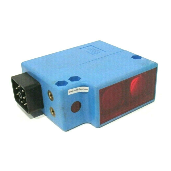
Photoelectric Proximity Switch
with background suspression
Operating Instructions
Safety Specifications
‡ Read the operating instructions before starting operation.
‡ Connection, assembly, and settings only by competent
technicians.
‡ Protect the device against moisture and soiling when
operating.
‡ No safety component in accordance with EU machine
guidelines.
Proper Use
The WT 36 photoelectric proximity switch is an optoelectronic
sensor and is used for detection of optical, non-contact
detection of objects, animals, and people.
Starting Operation
1
Open the cover of the sensor ; make sure that no dirt
enters the device.
2
The devices WT 36-N, -P have complementary switching
SICK AG
Schiess-Straße 56
outputs:
D-40549 Düsseldorf
WT 36-P only:
Fax: 02 11 53 01-1 00
Q: dark-switching, if light interrupted, output HIGH,
www.sick.de
Australia
Q: light-switching, if light received, output LOW.
Erwin Sick Optic-Electronic Pty. Ltd.
Ivanhoe
WT 36-N only:
Q: dark-switching, if light interrupted, output LOW,
Austria
SICK GmbH
Q: light-switching, if light received, output HIGH.
2355 Wiener Neudorf
WT 36-R only: y: y: y: y:
WT 36-R onl
WT 36-R onl
WT 36-R onl
WT 36-R onl
Belgium/Luxembourg
Sick nv/sa
Relay 1x u, separated galvanically.
Asse (Relegem)
3
With f
With f
ollo
ollo
wing connector
wing connector
s onl
s only: y: y: y: y: Connect and secure
s onl
With follo
With f
With f
ollowing connector
ollo
wing connector
wing connectors onl
s onl
Brazil
cable receptacle tension-free.
SICK Indústria & Comércio Ltda.
São Paulo
Only f y f y f y f y for v
Onl
Onl
or v
or ver er er er ersions with ter
or v
sions with terminal chamber
sions with ter
sions with ter
minal chamber
minal chamber : : : : : Disconnect
minal chamber
Onl
Onl
or v
sions with ter
minal chamber
PG cable, remove sealing plugs. Feed tension-free supply
China/Hong Kong
SICK Optic-Electronic Co., Ltd.
cable through and connect photoelectric switch as per
Kowloon
connection diagram B.
4
Czech Republic
Mount sensor to suitable holders (e.g. SICK mounting
SICK spol. sro.
Praha 5-Radotin
bracket).Maintain direction in which object moves relative
to sensor.Connect photoelectric proximity switch to
Denmark
operating voltage (see type label).
SICK A/S
Birkerød
5
Check application conditions such as scanning distance, size
Finland
and reflectance of object to be detected as well as of
SICK Optic-Electronic Oy
background, and compare with characteristic in diagram.
Helsinki
(x=scanning distance, y=transition range between set
France
scanning distance and reliable background suppression(z) in
SICK
Marne la Vallée
% of scanning distance, Ro=reflectance of object,
Rh=reflectance of background).Reflectance: 6%=black,
Great Britain
18%=gray, 90%=white (based on standard white to DIN
Erwin Sick Ltd.
St. Albans
5033).
6
Setting scanning distance: (X)
Remove object, signal strength indicator should go out
We reserve the right to make changes without prior notification
(position A=max.). If it does not go out, turn switch
towards min. until it goes out (e.g. position A). Set switch to
min. Position object. Turn switch towards max. until signal
strength indicator lights up (e.g. position B).
If position B<position A:
select middle setting (e.g. position C). Check complete
functioning. Functioning OK, setting completed. Functioning
not OK, check and readjust application conditions.
If position A<=position B:
Nur
Nur
Nur
Nur
Nur WT 36-R:
WT 36-R:
WT 36-R:
WT 36-R:
WT 36-R:
influence of background is too great. Check and readjust
Relais 1x u, galvanisch getrennt.
application conditions.
3
Nur bei den Stecker er er er er v v v v v er er er er ersionen:
Nur bei den Steck
Nur bei den Steck
Nur bei den Steck
Nur bei den Steck
7
Preselect time delays (t1 or t3=switch-on delay, t2 or
Leitungsdose spannungsfrei aufstecken und festschrauben.
t4=switch-off delay); switch setting t0=OFF.
Nur bei
Nur bei
Nur bei
Nur bei
Nur bei V V V V V er er er er ersionen mit Klemmenanschlußr
After time delay preselection, make fine adjustment on
Verschraubung lösen, Dichtungsstopfen entfernen. Spannungs-
switch (Y); setting range WT 36-N, -P: from 0.015 to 0.3
freie Versorgungsleitung durchführen und Lichtschranke nach
sec (t1, t2) and from 0.5 to 12 sec (t3, t4); WT 36-R: from
Anschlußschema B anschließen.
0.5 to 12 sec.
4
Sensor mit Befestigungsbohrungen an geeignete Halter
Check sealing faces, seals, and screwed joints, then replace
montieren (z.B. SICK-Haltewinkel).
and screw down cover.
Bewegungsrichtung des Objektes relativ zum Taster einhalten.
Options
Lichttaster an Betriebsspannung legen (s. Typenaufdruck).
5
Einsatzbedingungen wie Tastweite, Objektgröße und
The devices WT 36-P, -N 210 and 710 have a test input (TE)
test input (TE),
test input (TE)
test input (TE)
test input (TE)
Remissionsvermögen des Tastgutes sowie des Hintergrundes
with which proper functioning of the device can be checked.
überprüfen und mit der Kennlinie im Diagramm vergleichen.
When the light path is clear between the photoelectric switch
(x=Tastweite, y=Übergangsbereich zwischen eingestellter
and the object (the LED signal strength indicator lights), activate
Tastweite und sicherer Hintergrundausblendung (z) in % der
the test input (see the B connection diagram); this switches off
Tastweite, Ro=Remission Objekt, Rh=Remission Hinter-
the transmitter. At the same time, the LED signal strength
grund).
control must switch off, and the switching state at the output
must change.
Remission: 6%=schwarz, 18%=grau, 90%=weiß (bezogen auf
Standardweiß nach DIN 5033).
Maintenance
6
Einstellung Tastweite: (X)
SICK photoelectric switches do not require any maintenance.
Objekt entfernen, die Empfangsanzeige muß erlöschen
We recommend that you
(Position A=Max.). Leuchtet sie weiterhin, Drehknopf in
- clean the optical interfaces and
Richtung Min. drehen, bis sie erlischt (z.B. Position A).
- check the screw connections and plug-in connections at
Drehknopf auf Min. stellen. Objekt positionieren. Drehknopf
regular intervals.
in Richtung Max. drehen, bis die Empfangsanzeige aufleuchtet
(z.B. Position B).
Wenn Position B<Position A:
Mittelstellung wählen (z.B. Position C). Gesamtfunktion
überprüfen. Funktion o.k., Einstellung beendet. Funktion nicht
o.k., Einsatzbedingungen überprüfen und neu justieren.
DEUTSCH
Wenn Position A<=Position B:
Reflexions-Lichttaster
Hintergrundeinfluß ist zu groß. Einsatzbedingungen überprü-
mit Hintergrundausblendung
fen und neu justieren.
Betriebsanleitung
7
Zeitstufen (t1 oder t3=Einschaltverzögerung, t2 oder
t4=Ausschaltverzögerung) vorwählen; Schalterstellung
Sicherheitshinweise
t0=AUS.
‡ Vor der Inbetriebnahme die Betriebsanleitung lesen.
Nach Zeitstufenvorwahl nun die Feineinstellung am Dreh-
‡ Anschluß, Montage und Einstellung nur durch Fachpersonal.
knopf (Y) vornehmen; Einstellmöglichkeit: WT 36-N, -P: von
‡ Gerät bei Inbetriebnahme vor Feuchte und Verunreinigung
0.015 bis 0.3 sec (t1, t2) und von 0.5 bis 12 sec (t3, t4); WT
schützen.
36-R: von 0.5 bis 12 sec.
‡ Kein Sicherheitsbauteil gemäß EU-Maschinenrichtlinie.
Dichtflächen, Dichtungen und Verschraubungen kontrollieren,
dann Deckel aufsetzen und festschrauben.
Bestimmungsgemäße Verwendung
Der Reflexions-Lichttaster WT 36 ist ein opto-elektronischer
Optionen
Sensor und wird zum optischen, berührungslosen Erfassen von
Die Geräte WT 36-P, -N 210 und 710 verfügen über einen
Sachen, Tieren und Personen eingesetzt.
T T T T T esteingang (TE)
esteingang (TE)
esteingang (TE)
esteingang (TE), mit dem die ordnungsgemäße Funktion der
esteingang (TE)
Inbetriebnahme
Geräte überprüft werden kann. Bei freiem Lichtweg zwischen
Lichttaster und Objekt (Empfangsanzeige leuchtet) den Testeingang
1
Deckel des Sensors öffnen; darauf achten, daß kein Schmutz
aktivieren (s. Anschlußschema B); dadurch wird der Sender
in das Gerät gelangt.
abgeschaltet. Gleichzeitig muß die Empfangsanzeige erlöschen, und
2
Die Geräte WT 36-N, -P haben antivalente Schaltausgänge:
der Schaltzustand am Ausgang muß sich ändern.
Nur WT 36-P:
Wartung
Q: dunkelschaltend, bei Lichtunterbrechung Ausgang HIGH,
Q: hellschaltend, bei Lichtempfang Ausgang LOW.
SICK-Lichttaster sind wartungsfrei. Wir empfehlen, in regelmäßigen
Nur WT 36- N:
Abständen
- die optischen Grenzflächen zu reinigen,
Q: dunkelschaltend, bei Lichtunterbrechung Ausgang LOW,
- Verschraubungen und Steckverbindungen zu überprüfen.
Q: hellschaltend, bei Lichtempfang Ausgang HIGH.
A
8 005 955.0699 HJS KE
WT 36
Italy
SICK S.p.A.
Cernusco sul Naviglio -MI-
02 11 53 01-0
02 92 14 20 62
Japan
SICK Optic-Electronic K.K.
Tokyo
03 33 58-13 41
03 94 97 41 00
Netherlands
SICK B. V.
AD Bilthoven
0 30 2 29 25 44
0 22 36 622 88-0
Norway
SICK AS
Gjettum
67 81 50-0
02 4 66 55 66
Poland
SICK Optic-Electronic Sp. z. o. o.
Warszawa
022 8 37 40 50
011 55 61 26 83
Singapore
SICK Optic-Electronic Pte. Ltd.
Singapore 387 383
65 7 44 37 32
20 27 63 69 66
Spain
SICK Optic-Electronic S. A.
Sant Just Desvern
93 4 80 31 00
02 578 10 561
B
Sweden
SICK AB
Vårby
08 6 80 64 50
45 82 64 00
Switzerland
SICK AG
Stans
041 6 19 29 39
09 7 28 85 00
Taiwan
SICK Optic-Electronic Co., Ltd.
Taipei
02 23 65 62 92
1 64 62 35 00
USA
SICK, Inc.
Bloomington, MN 55438
(952) 9 41-67 80
0 17 27 83 11 21
Änderungen vorbehalten
Sous réserve de modifications
Reser vam-se alteraç ões
Ret til ændringer forbeholdes
Con riserva di modifiche
Wijzigingen voorbehouden
Reservado el derecho a introducir modificaciones
sionen:
sionen:
sionen:
sionen:
sionen mit Klemmenanschlußr
sionen mit Klemmenanschlußr
sionen mit Klemmenanschlußr
sionen mit Klemmenanschlußraum:
aum: PG-
aum:
aum:
aum:
1
4
2
5
6
7
3
Advertisement
Table of Contents

Related Manuals for SICK SENSICK WT 36


Summary of Contents for SICK SENSICK WT 36
- Page 1 B. 20 27 63 69 66 Spain SICK Optic-Electronic S. A. Czech Republic Mount sensor to suitable holders (e.g. SICK mounting Sant Just Desvern SICK spol. sro. 93 4 80 31 00 Praha 5-Radotin bracket).Maintain direction in which object moves relative...
- Page 2 Pakflader, pakninger og forskruninger kontrolleres, derefter adecuado (p. ej. escuadra SICK de soporte). Conservar el Introduzir o cabo de força sem torções e ligar a barreira de ‡ Lors de la mise en service, protéger l’appareil de l’humidité et ‡...
Need help?
Do you have a question about the SENSICK WT 36 and is the answer not in the manual?
Questions and answers