Advertisement
Quick Links
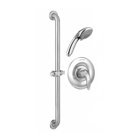
COMMERCIAL SHOWER
SYSTEM KITS: 1.5 gpm & 2.5 gpm
Thank you for selecting American-Standard...the benchmark
of fine quality for over 100 years.
To ensure that your installation proceeds smoothly--please
read these instructions carefully before you begin.
Installation must conform to all local building codes.
Recommended Tools & Materials
Phillips Screwdriver
Pipe Wrench
ROUGHING-IN DIMENSIONS
FINISHED
WALL
36"
3-1/8" DIA.
1-5/8"
37-1/2"
OPTIONAL TO FINISHED FLOOR
USUALLY BETWEEN
36"
Pencil
Hammer
Adjustable Wrench
8"
OPTIONAL
3-1/8" DIA.
3-1/8" DIA.
TO
60"
1/2" SUPPLIES
48"
Universal Inlets / Outlets:
1/2" NOM Copper Sweat or 1/2" NPT
Installation
Instructions
1662SG.211
1662SG.221
Sealing Tape
Tape
Measure
Tubing Cutter
3-5/16"
1/2" NPSM
12"
OPTIONAL
5-7/8"
PLUG TUB
OUTLET
BOTTOM OF SHOWER
16 6 2 S G . 2 11 ( 1. 5 g p m )
16 6 2 S G . 2 2 1 ( 2 . 5 g p m )
Certified to comply with ANSI A112.18.1
M 9 6 5 6 6 6 R ev. 1. 0 ( 1 / 17 )
10'
6mm (15/64")
Drill Bit
Electric Drill
1660766.002
(1.5 gpm)
1660767.002
(2.5 gpm)
FINISHED WALL
1-5/8" TO 3-1/4"
1/2"
1/2" NPT
1-1/4"
6" DIA.
OPTIONAL TO FINISHED
BETWEEN 48" TO 54"
Torch
FLOOR USUALLY
Advertisement

Related Manuals for American Standard 1662SG.211


Summary of Contents for American Standard 1662SG.211
- Page 1 16 6 2 S G . 2 11 ( 1. 5 g p m ) COMMERCIAL SHOWER 1662SG.211 16 6 2 S G . 2 2 1 ( 2 . 5 g p m ) SYSTEM KITS: 1.5 gpm & 2.5 gpm 1662SG.221...
- Page 2 INSTALL THE R121SS VALVE BODY NOTE REFER TO INSTALLATION INSTRUCTIONS (M965661) SUPPLIED WITH VALVE BODY FOR COMPLETE INSTALLATION AND REPAIR PART INFORMATION. IMPORTANT When soldering, remove PLASTER GUARD, CARTRIDGES and CHECK STOPS R121SS (IF PRESENT). When finished soldering, flush valve body, replace cartridges, check stops (if present) and plaster guard to continue installation.
-
Page 3: Installation Instructions
INSTALLATION INSTRUCTIONS The GRAB BAR (1) works best when secured to the wall studs or cross brace using WOOD SCREWS. If mounting into the studs is not possible, use appropriate wall fasteners provided to secure the installation. Mark a vertical center line in the location you wish to install the SLIDE BAR (1). NOTE: The height from the finished floor is optional. - Page 4 INSTALL HOSE AND HAND SHOWER TEST SHOWER SYSTEM Install SEAL (1) into COUPLING NUT (2). Connect COUPLING NUT (2) to WALL SUPPLY NIPPLE (3) and tighten. INSTALL second SEAL (4) into SPRAY HOSE END (5) and connect HAND SHOWER (6) to SPRAY HOSE END (5). Hand tighten. Turn on water supplies and check all fuctions of of the SHOWER SYSTEM KIT.
- Page 5 36" SLIDE BAR 1660.236.002 3-FUNCTION HAND SHOWER 1660766.002 (1.5 gpm) 1660767.002 (2.5 gpm) M9641800020A SPRAY HOLDER ASSEMBLY WALL SUPPLY M964179-0070A MOUNTING KIT 8888.037.002 8888037.002 WALL SUPPLY M962520-0020A CHECK VALVE METAL HOSE 8888.035.002 030782-0020A HOSE KIT Appropriate finish code CHROME HOT LINE FOR HELP For toll-free information and answers to your questions, call: 1 (800) 442-1902 Mon.