Advertisement
Quick Links
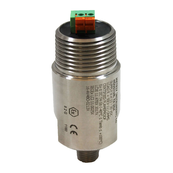
ST5484E 2-WIRE SEISMIC VIBRATION TRANSMITTER
Installation Manual
Flying Leads
2-Pin Terminal Block
1180
DOC# M9162 • REV AB (April 2019)
4-Pin Terminal Block
2-Pin MIL Connector
1. OVERVIEW
The ST5484E Seismic Vibration Transmit-
ter combines a vibration sensor and signal
conditioner in a single package for sensing
machinery vibration level and transmitting a
proportional 4-20 mA signal directly to PLCs,
DCSs, monitors, and computers. Versions
with 2 wires, 4 wires, terminal blocks, or
MIL-type connector are available.
The transmitter has no moving parts and is
encapsulated in a stainless steel housing.
Each transmitter is factory calibrated to the
sensitivity marked on the label. An optional
dynamic signal output can be specified.
Refer to Metrix Datasheet 1004457 for
specifications, ordering information, and
outline dimensions.
2. MOUNTING
It is important to solidly mount the transmit-
ter body to the machine surface. Refer to
section 6 on transducer placement. Differ-
ent machine preparations are required for
the two basic transmitter mounting styles;
NPT (National Pipe Thread) and machine
thread (UNF and Metric). Transmitters with
the NPT type mounting stud are secured by
the thread engagement and the base of the
transmitter does not contact the machine
surface. Transmitters with the machine
thread studs must contact the machine
surface. The base of the transmitter must
make square and direct contact. This re-
quires preparing the surface of the machine
with a 1 1/2 inch counter bore (surfacing
tool). This tool can be used with a portable
Advertisement

Related Manuals for Metrix ST5484E


Summary of Contents for Metrix ST5484E
- Page 1 ST5484E 2-WIRE SEISMIC VIBRATION TRANSMITTER Installation Manual 1. OVERVIEW The ST5484E Seismic Vibration Transmit- ter combines a vibration sensor and signal conditioner in a single package for sensing machinery vibration level and transmitting a proportional 4-20 mA signal directly to PLCs, DCSs, monitors, and computers.
- Page 2 • 20-26 AWG stranded copper conductors The ST5484E transmitter requires a minimum of 11 VDC for proper operation. This is the mini- mum voltage required at the transmitter (not the power supply), after all other voltage drops across field wiring and receiver input impedance have been accounted for with the maximum 20mA of loop current flowing.
- Page 3 Connect the field wiring in accordance with Metrix drawing 9426 for CSA Class I, (A,B,C & D) and Metrix drawing 9278 for IECEx / ATEX (Ex ia IIC T4 Ga) approvals. The leads must be terminated inside an enclosure with a degree of protection of at least IP20. A Metrix elbow from the 8200 series may be used for these purposes.
- Page 4 Doc# (April 2019) Page 4 of 12 M9162• REV AB...
- Page 5 Doc# (April 2019) Page 5 of 12 M9162• REV AB...
-
Page 6: Electromagnetic Compatibility
WARNING: ATEX Conditions for Safe Use (Ex ia) The ST5484E is intrinsically safe and can be used in potentially explosive atmo- spheres. This transmitter must only be associated to intrinsically safe certified appara- tus, and this combination must be compatible as regards intrinsic safety. - Page 7 The first step in configuring the PLC, DCS, or other recording instrument is to determine the source of power. The ST5484E requires loop power. Some analog input channels on a PLC or DCS, for example, provide this power from within. If they do not provide power, an external power supply must be provided.
- Page 8 • A “Y” type conduit elbow, such as the Metrix 8200 series, is preferred because it prevents the conduit from extending too far away from the transmitter, thus limiting the likelihood of break- age.
- Page 9 8. CALIBRATION The ST5484E transmitter has been factory calibrated for the full-scale vibration level marked on the label. If the calibration is in doubt, the unit can be verified in the field by following the procedures outlined below. Note that there are no Zero and Span adjustments on the transmitter.
- Page 10 4-20mA velocity measurement (refer to options E and F on the Metrix Datasheet 1004457). Observe the following when using this output: • Only an electrically-isolated or battery- powered portable vibration analyzer should be used when connecting to this output.
- Page 11 10. SPECIFICATIONS, ORDERING INFORMATION AND OUTLINE DIMENSIONAL DIAGRAMS Refer to Metrix product datasheet 1004457 for additional information. Figure 2: Outline dimensions of the Figure 1: Outline dimensions of the ST5484E (all ST5484E-XXX-XX4-XX (MIL-Style Connector). versions except MIL-Style Connector). Dimen- Dimensions in mm [inches].
-
Page 12: Environmental Information
WEEE) should never be disposed of in the public waste stream. The “Crossed-Out Waste Bin” label affixed to this product is a reminder to dispose of this product in accordance with local WEEE regulations. If you have questions about the disposal pro- cess, please contact Metrix Customer Service. info@metrixvibration.com www.metrixvibration.com 8824 Fallbrook Dr.
Need help?
Do you have a question about the ST5484E and is the answer not in the manual?
Questions and answers