Table of Contents
Advertisement
Quick Links
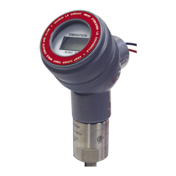
ST5491E 2-WIRE SEISMIC VIBRATION TRANSMITTER
Installa on Manual
DOC# M9344 • REV J (Feb 2019)
OVERVIEW
The Model ST5491E Seismic Vibra on Trans-
mi er is the latest version of an established
series of transmi ers from Metrix. The
ST5491E is the indica ng version of Metrix
Model ST5484E and comes with an integral
2-1/2 digit LCD indicator for local vibra on
readout. It incorporates state-of-the-art
electronic components and circuits. It also
off ers several new op ons in terms of fea-
tures and confi gura ons.
The transmi er combines a vibra on sensor
and signal condi oner in a single package.
They provide the ideal solu on for sensing
machinery vibra on level and transmi ng
a propor onal 4-20 mA signal directly to a
PLC, DCS, monitor, or computer. Typical ap-
plica ons include low- and medium-speed
machines such as fans, blowers, pumps, mo-
tors, and centrifuges. The transmi er can
be supplied with op onal screw cover elbow
fi ngs for connec ng fl exible conduit.
The transmi er is all solid state, has no
moving parts, and is encapsulated in a
stainless steel housing. The LCD indicator
is packaged in a sealed module that can be
posi oned in 90° increments with the elbow
fi ng to allow proper viewing when the
transmi er is installed. Each transmi er is
factory calibrated to the sensi vity marked
on the label.
Advertisement
Table of Contents

Related Manuals for Metrix ST5491E


Summary of Contents for Metrix ST5491E
- Page 1 The Model ST5491E Seismic Vibra on Trans- mi er is the latest version of an established series of transmi ers from Metrix. The ST5491E is the indica ng version of Metrix Model ST5484E and comes with an integral 2-1/2 digit LCD indicator for local vibra on readout.
- Page 2 The sensi ve axis of the transmi er is in line with the moun ng stud. The transmi er can be oriented in any (0 to 360 degree) posi on. 2. WIRING The ST5491E is connected like any other loop powered transmi er. The following is a sum- mary based on area designa ons. 2.A SAFE AREA INSTALLATION Connect the fi...
- Page 3 2.B EXPLOSION-PROOF INSTALLATION IN HAZARDOUS LOCATIONS ST5491E transmi ers are CSA cer fi ed explosion-proof, Class I (C & D); Class II (E, F & G,). Connect the fi eld wiring in accordance with the appropriate diagram on page 3. Refer to paragraph 2.A for loop voltage and resistance requirements.
- Page 4 A 2- to 3-second delay is normally applied to most machinery. Consult Metrix if you have a ques on about your machines opera ng characteris cs.
- Page 5 Figure 2: Flying leads spliced in conduit elbow. CALIBRATION The ST5491E transmi er has been factory calibrated for the full scale vibra on level marked on the label. If the calibra on is in doubt the unit can be verifi ed in the fi eld by following the procedures outlined below.
- Page 6 3. Digital Indicator Calibra on of the Digital Indicator requires par al disassembly of the ST5491E. Remove the Digital Indicator threaded cover. Carefully remove the electronics module using a small fl at head screwdriver. Note how the transmi er wires are connected before disconnec ng them.
- Page 7 OPTIONAL ACCESSORIES The ST5491E is available with diff erent moun ng op ons. The performance of the transmit- ter does not change (except for the dynamic output op on, discussed). MOUNTING 8201-001, Conduit Union Fits between transmi er and 8200-001 conduit elbow to facilitate installa on and wiring where there is not enough room to rotate the elbow.
- Page 8 The “Crossed-Out Waste Bin” label affi xed to this product is a reminder to dispose of this product in accordance with local WEEE regula ons. If you have ques ons about the disposal process, please contact Metrix Customer Services. info@metrixvibra on.com www.metrixvibra on.com...
Need help?
Do you have a question about the ST5491E and is the answer not in the manual?
Questions and answers