Table of Contents
Advertisement
Quick Links
Manual
ST5484E 2-Wire Seismic Vibration Transmitter
1. Overview
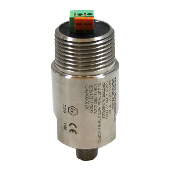
The Model ST5484E Seismic Vibration Transmitter combines a vibration sensor and signal
conditioner in a single package for sensing machinery vibration level and transmitting a
proportional 4-20 mA signal directly to a PLC, DCS, monitor, or computer. The 2-wire flying lead
version is shown at right. Versions with 4 wires, terminal blocks, or MIL-type connector are also
available.
The transmitter has no moving parts and is encapsulated in a stainless steel housing. Each
transmitter is factory calibrated to the sensitivity marked on the label. An optional dynamic
signal output can be specified.
2. Mounting
It is important the transmitter body be solidly mounted to the machine surface. Refer to section 6 on transducer placement.
Different machine preparations are required for the two basic transmitter mounting styles; NPT (National Pipe Thread) and
machine thread (UNF and Metric). Transmitters with the NPT type mounting stud are secured by the thread engagement and
the base of the transmitter does not come in contact with the machine surface. On the other hand, transmitters with the
machine thread studs must make contact with the machine surface. The base of the transmitter must make square and
direct contact. This requires preparing the surface of the machine with a 1 1/2 inch counter bore (surfacing tool). This tool
can be used with a portable drill equipped with a magnetic base but care must be taken so that the tapped and threaded hole
is perpendicular to the machined surface. The transmitter must make contact all the way around its base surface. Contact
Metrix for more detailed instructions for using a counter bore.
If installing a transmitter with a standard 1/4 inch NPT stud, drill a hole using a 7/16 inch bit, 5/8-7/8 inch deep. Then tap
using a 1/4 - 18 NPT (tapered pipe tap). Hand tighten the transmitter and then turn an additional 1 to 2 turns using a wrench
on the wrench flats. Do not use a pipe wrench. A pipe wrench can apply extreme forces to the body and potentially damage
electronic components. A minimum of five (5) threads of engagement should be made. A 1/4 inch to 1/2 inch NPT bushing is
available for mounting the transmitter in existing 1/2 inch NPT holes. Also, a Model 7084 Flange Adapter can be used
between the transmitter and the machine surface when there is not enough surface thickness to drill and tap a hole. The
flange adaptor mounts with three small screws.
If installing a transmitter with one of the straight machined thread sizes, follow standard drill and tap procedures. Be sure to
not drill a hole larger that the counter bore pilot diameter before using the counter bore to prepare the machine surface.
Drill out the hole with the correct tap drill size after preparing the surface.
The sensitive axis of the transmitter is in line with the mounting stud. The transmitter can be oriented in any (0 to 360
degree) position.
Document 9162
Rev. T (Oct 2013)
Advertisement
Table of Contents

Related Manuals for Metrix ST5484E


Summary of Contents for Metrix ST5484E
- Page 1 ST5484E 2-Wire Seismic Vibration Transmitter 1. Overview The Model ST5484E Seismic Vibration Transmitter combines a vibration sensor and signal conditioner in a single package for sensing machinery vibration level and transmitting a proportional 4-20 mA signal directly to a PLC, DCS, monitor, or computer. The 2-wire flying lead version is shown at right.
- Page 2 Figure 1 The ST5484E transmitter requires a minimum of 11 VDC for proper operation. This is the minimum voltage required at the transmitter (not the power supply), after all other voltage drops across field wiring and receiver input impedance have been accounted for with the maximum 20mA of loop current flowing.
- Page 3 3.3 Explosion-Proof Installation In Hazardous Locations (CSA) ST5484E transmitters are CSA certified explosion-proof, Class I (B, C & D); Class II (E, F & G,). Connect the field wiring in accordance with the appropriate portion of Figure 1. Refer to paragraph 3.1 for loop voltage and resistance requirements.
- Page 4 The first step in configuring the PLC, DCS, or other recording instrument is to determine the source of power. The ST5484E requires loop power. Some analog input channels on a PLC or DCS, for example, provide this power from within.
- Page 5 6. Typical Transmitter Placement The ST5484E measures seismic vibration (i.e., vibration velocity) at the attachment point on the machine, using engineering units of in/s (inches per second) or mm/s (millimeters per second) depending on which ordering option has been selected. The transmitter’s sensitive direction is through the long axis of its cylindrical body.
- Page 6 • A “Y” type conduit elbow such as the Metrix 8200 is preferred because it prevents the conduit from extending too far away from the transmitter, thus limiting the likelihood of breakage by personnel working on or near the machine.
- Page 7 Trademarks used herein are the property of their respective owners. Data and specifications subject to change without notice. © 2013 Metrix Instrument Company, L.P. Document 9162 Manual - ST5484E 2-Wire Seismic Vibration Transmitter Page 7 of 7 Rev. T (Oct 2013)
Need help?
Do you have a question about the ST5484E and is the answer not in the manual?
Questions and answers