
Related Manuals for Dwyer Instruments UFC Series


Summary of Contents for Dwyer Instruments UFC Series
- Page 1 Bulletin F-UFC Series UFC Ultrasonic Flowmeter Kit Installation and Operating Instructions 1.800.561.8187 information@itm.com www. .com...
-
Page 2: Table Of Contents
Table of Contents 1: General Description 1.1 Introduction 1.2 Principles of Operation 1.3 Supplied Hardware 1.4 UFC Instrument 1.4.1 Connections 1.4.2 Keypad 1.4.3 Power supply 2: Installation 2.1 Safety Precautions and Warnings 2.2 Installing the UFC Instrument 2.2.1 Positioning the instrument 2.2.2 Mounting the instrument 2.2.3 Connecting the instrument 2.3 Installing the Ultrasonic Transducers... - Page 3 3.4.3 Alarm outputs 3.5 How to Measure Totalized Flows (manually) 3.6 Display of totalizers 3.7 Operation with an Energy Meter 3.7.1 Pulse output 3.7.2 Configuring the UFC 4: Data Logging 4.1 How to Set Up the Basic Logging Application to Memory 4.2 How to Set Up Automatic (Timed) Logging Mode 4.3 How to Download Logged Data 5: Maintenance &...
-
Page 4: 1: General Description
1: General Description 1: General Description Introduction This manual describes the operation of the Dwyer UFC flowmeter. The flowmeter is designed to work with clamp- on transducers to enable the flow of a liquid within a closed pipe to be measured accurately without needing to insert any mechanical parts through the pipe wall, or protrude into the flow system. -
Page 5: Principles Of Operation
1: General Description Note: In addition to the 'A' and 'B' type sensors, type 'D' sensors (option) are available for use on pipes up to 197 inches (5000 mm). These sensors have a different mounting method. See Paragraph 1.3 for further details. Principles of Operation Separation Upstream... -
Page 6: Supplied Hardware
1: General Description the instrument’s microprocessor can use the results of the transit time calculations to compute the fluid flow velocity. Once the flow velocity is known the volumetric flow can be easily calculated for a given pipe diameter. The system can be set up to operate in one of four modes, determined mainly by the pipe diameter and the type of transducer set in use. -
Page 7: Ufc Instrument
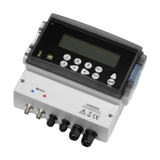
1: General Description separate case and includes the type 'D' transducers together with ratchet straps and holders for attaching the transducers to the pipe. UFC Instrument The UFC is a microprocessor controlled instrument operated through a menu system using an inbuilt LCD display and keypad. -
Page 8: Keypad
1: General Description 1.4.2 Keypad The instrument is configured and controlled via a 15-key tactile membrane keypad, as shown in Figure 1.4. Scroll UP ENTER (SELECT) Scroll DOWN Numerical keypad Scroll LEFT Scroll RIGHT with dual function keys Figure 1.4 UFC Keypad Menus and the menu selection keys Note: As a security measure, once the instrument has been set-up for the first time, a password is required to gain subsequent access to the operating menus (see page 22). -
Page 9: Power Supply
1: General Description 1.4.3 Power supply Mains supply As standard, the UFC instrument is designed to work with a mains supply of 86 to 236 Vac and 50/60 Hz. A mains supply fuse is located adjacent to the mains power connection (see Figure 2.2). 24V Supply An alternative 24 V (ac/dc) power supply module is available as a factory fitted option. -
Page 10: 2: Installation
2: Installation 2: Installation Safety Precautions and Warnings LETHAL VOLTAGES You may be exposed to potentially lethal (mains) voltages when the terminal cover of this instrument is removed. WARNING Always isolate the supply to this instrument before removing the terminal cover. LETHAL VOLTAGES This instrument must be installed by an electrically qualified technician aware of the potential shock hazards presented... -
Page 11: Mounting The Instrument
2: Installation 2.2.2 Mounting the instrument Ideally, the UFC enclosure should be fixed to a wall using three screws – see Figure 2.2. Remove the UFC terminal cover. Fix a screw into the wall at the required point to align with the mounting keyhole on the back of the enclosure. Attach the enclosure to the wall using the keyhole screw mounting. -
Page 12: Connecting The Instrument
2: Installation 2.2.3 Connecting the instrument All cables enter the instrument through the (4) cable glands located at the bottom of the instrument and are connected by means of screwed terminals to a number of plug-in connectors – see Figure 2.1. Control &... -
Page 13: Installing The Ultrasonic Transducers
2: Installation Installing the Ultrasonic Transducers 2.3.1 Transducer positioning The UFC equipment expects a uniform flow profile as a distorted flow will produce unpredictable measurement errors. Flow profile distortions can result from upstream disturbances such as bends, tees, valves, pumps and other similar obstructions. Uniform Flow Profile Distorted Flow Profile Transducer... -
Page 14: Transducer Attachment
2: Installation To obtain the most accurate results, the condition of both the liquid and the pipe wall must be suitable to allow the ultrasound transmission along its predetermined path. It is important also that the liquid flows uniformly within the length of pipe being monitored and that the flow profile is not distorted by any upstream or downstream obstructions. -
Page 15: Attaching The Guide Rail To The Pipe
2: Installation Note: When using the UFC in the ‘diagonal’ mode, or in ‘reflex’ mode on pipes over 13.75 inches diameter, two guide rails are required with a transducer mounted in each one – see Paragraph 2.3.5 for diagonal mode details. 2.3.3 Attaching the guide rail to the pipe Position the guide rail horizontally on the pipe at 45°... - Page 16 2: Installation Note: When carrying out the following steps handle the transducer assembly with care to avoid smearing the acoustic couplant on the pipe whilst attaching the transducer to the guide rail. Carefully lower the transducer and cable through the rectangular opening until the slots in the side of the transducer clamp align with the edges on the top of the guide rail.
- Page 17 2: Installation 10. Position the upstream transducer so that the inner Calculated separation distance face of the transducer is set to the required separation distance on the ruler, as shown in Figure 2.12 (2 inches in this example). Note: The separation distance for a particular application can be found using the ‘Quickstart’...
-
Page 18: Transducer Attachment (Diagonal Mode)
2: Installation 2.3.5 Transducer attachment (diagonal mode) This mode of operation requires two transducer holders fitted on opposite sides of the pipe, as shown in Figure 2.15 – notice that the transducer holders are still fitted on a 45° axis with respect to the top of the pipe. When used with type ‘A’... - Page 19 2: Installation 45° Separation Distance Upstream transducer 45° Flow Downstream transducer HINT: An easy way to draw a perpendicular circumference around a large pipe is to wrap a length of material such as chart paper around the pipe, aligning the edges of the paper precisely at the overlap. With the edge of the chart paper being parallel, either edge describes a circumference around the pipe that is perpendicular to the pipe axis.
-
Page 20: 3: Operating Procedures
3: Operating Procedures 3: Operating Procedures Initial instrument setup Paragraph 3.1 Set date/time, Language Connect and take basic flow readings Paragraph 3.2 QUICK START Enter data Attach sensors FLOW READING Carry out any necessary calibration (Paragraph 3.3) How to adjust the Zero Flow Offset – Paragraph 3.3.2 How to adjust the Calibration Factor –... -
Page 21: Setting-Up The Instrument
3: Operating Procedures Setting-up the Instrument Key Point: When the instrument used for the first time the operator has free access to all the set-up and operating menus until the instrument is put into FLOW READING operation, where-upon all the menus become password protected (see page 22). 3.1.1 Using the instrument for the first time Initial user language selection The first time you power-up the instrument you will be asked to select a user language, which will then be the... -
Page 22: Changing The User Language
3: Operating Procedures 3.1.2 Changing the user language If you want to change the user language at any time SETUP INSTRUMENT DD-MM-YY HH:MM:SS after the instrument has been put into operation: Select Setup Instrument from the MAIN Set Date & Time : dd-mm-yy hh:mm:ss MENU then press ENTER. - Page 23 3: Operating Procedures Enter the pipe outside diameter dimension, OUTSIDE DIAMETER DD-MM-YY HH:MM:SS then press ENTER. Dimensions: Inches Pipe outside diameter: 6.50 Enter the pipe wall thickness dimension, then PIPE WALL THICKNESS DD-MM-YY HH:MM:SS press ENTER. Dimensions: Inches Pipe outside diameter: 6.50 Pipe wall thickness: 0.50...
- Page 24 3: Operating Procedures If a lining thickness value was entered earlier, PIPE LINING MATERIAL DD-MM-YY HH:MM:SS this screen is displayed to request that you enter the lining material type. If no lining Select pipe lining material thickness was entered this screen will be bypassed.
- Page 25 3: Operating Procedures Selecting the operating mode On large pipes using either type ‘B’ or ‘D’ sensors it may be necessary to use the ‘Diagonal’ mode of operation rather than the ‘Reflex’ mode. The system will automatically select ‘Reflex’ mode if it is valid, but the mode can be changed using the following steps.
-
Page 26: Instrument Calibration
3: Operating Procedures units by pressing keys 7 (liters), 8 (Gallons, Barrels) or 9 (m³), or change the display to show velocity by pressing key 4. If the flow reading exceeds a value of +/-9999 in the current units, then a *10 multiplier will be displayed above the units and the value displayed will be a tenth of the actual value. -
Page 27: Adjusting The Calibration Factor
3: Operating Procedures ±0.005m/s (possibly higher on smaller diameter pipes). If a greater figure is shown, it is worth cancelling the offset to obtain a more accurate result. Continue as follows: Press the Options key to access the FLOW FLOW READING OPTION DD-MM-YY HH:MM:SS READING OPTION screen shown. - Page 28 3: Operating Procedures Press the Options key to access the FLOW FLOW READING OPTION DD-MM-YY HH:MM:SS READING OPTION screen shown. Scroll down and select Calibration factor Data review then press ENTER. Zero Cutoff (m/s) 0.010 Set zero flow (m/s) 0.000 Change the calibration factor according to the Damping (secs) error calculated in step 3.
-
Page 29: Adjusting The Roughness Factor
3: Operating Procedures 3.3.4 Adjusting the roughness factor The roughness factor compensates for the condition of the internal pipe wall, as a rough surface will cause turbulence and affects the flow profile of the liquid. In most situations it is not possible to inspect the pipe internally and the true condition is not known. - Page 30 3: Operating Procedures Press the Options key to access the FLOW FLOW READING OPTION DD-MM-YY HH:MM:SS READING OPTION screen shown. Scroll down and select Damping (secs) and Data review press ENTER. This will open the DAMPING Zero Cutoff (m/s) 0.010 Set zero flow (m/s) 0.000 OPTION screen.
-
Page 31: Outputs
3: Operating Procedures Outputs The UFC has configurable Current, Pulse, and Alarm outputs. 3.4.1 Current output Note: Where long cable runs are necessary, or noise pickup is causing unstable flow readings, the use of two core screened cable such as BELDEN 9501 060U500, or similar, is recommended for use with the 4 to 20 mA current output. - Page 32 3: Operating Procedures Connect a calibrated ammeter to the 4 to 20 mA CALIBRATE 4mA DD-MM-YY HH:MM:SS output and adjust the UP/DOWN Scroll keys (Coarse) and LEFT/RIGHT Scroll keys 5 & 6 Adjust the output current to 4mA (fine) until the output is exactly 4.00 mA. to set, 5/6 to trim ...
-
Page 33: Pulse Output
3: Operating Procedures How to convert the measured current to flow rate Assume the maximum flow rate is F (gal/min) and the minimum flow rate F is ‘0’ (gal/min), as shown. [0-16 mA scale] [0-20 mA scale] [4-20 mA scale] I (mA) To calculate the flow rate (gal/min) for a measured current I(mA) then: 0-20 mA... -
Page 34: Alarm Outputs
3: Operating Procedures How to turn the pulse output OFF/ON With the instrument operating in the FLOW PULSE OUTPUT DD-MM-YY HH:MM:SS READING mode, press the Pulse function key Pulse output is ON to access the PULSE OUTPUT menu. Flow units gallons Select Output and press ENTER. - Page 35 3: Operating Procedures Alarm configuration To setup Alarm 1, select Alarm1 Mode and ALARM SETTINGS DD-MM-YY HH:MM:SS press ENTER. This will access the ALARM1 MODE menu screen (shown below). Alarm1 Mode Alarm1 Level <value> Alarm2 Mode Alarm2 Level <value> Exit Alarm1 ON Alarm2 ON Scroll down the menu to the required alarm...
- Page 36 3: Operating Procedures Resetting an alarm When either Alarm1 or Alarm2 is activated, the appropriate relay will be held in the closed position until: • The activation condition is removed, or • The Alarm is reset. Both Alarm1 and Alarm2 can be reset by using one of the following procedure: Access the The ALARM SETTINGS menu by FLOW READING OPTION DD-MM-YY...
-
Page 37: How To Measure Totalized Flows (Manually)
3: Operating Procedures How to Measure Totalized Flows (manually) The basic measurement indicated on the FLOW READING screen is the instantaneous flow rate, which in some applications may vary over a period of time. Average flow rates are therefore often required in order to get a better understanding of an application’s true performance. -
Page 38: Display Of Totalizers
3: Operating Procedures Display of totalizers FLOW READING OPTION DD-MM-YY HH:MM:SS To change the display of the totalizers, select the Select Totals menu item from the FLOW READING OPTION menu. Both The display of the totals on the FLOW +Total -Total READING screen is controlled by this menu. - Page 39 3: Operating Procedures Select Alarm 1 Mode and press ENTER to ALARM SETTINGS DD-MM-YY HH:MM:SS select the ALARM1 MODE menu shown below: Alarm1 Mode Alarm1 Level Alarm2 Mode Alarm2 Level Exit Scroll down to Frequency and press ENTER. ALARM1 MODE DD-MM-YY HH:MM:SS This returns to the ALARM SETTINGS menu...
-
Page 40: 4: Data Logging
4: Data Logging 4: Data Logging How to Set Up the Basic Logging Application to Memory This procedure shows you how to set up a basic logging session under manual start/stop control. Logged data is saved to the instrument’s memory and can be down loaded to a PC at a later time. Both the flow rate and totals will be logged Setting up and starting the logging With the UFC operating in FLOW READING... - Page 41 4: Data Logging Press the Logger function key as described REAL TIME LOGGER above to switch to the REAL TIME LOGGER Logging to SD card screen. Unit : l/min Select View log as text. Log name : Quickstart Log data to : USB Logging interval : 10 seconds...
-
Page 42: How To Set Up Automatic (Timed) Logging Mode
4: Data Logging How to Set Up Automatic (Timed) Logging Mode This procedure shows you how to set up an auto logging session under timed start/stop control. The logged data is saved to the instrument’s memory and can be downloaded at a later time. Starting point This procedure assumes that the instrument has been correctly installed and is operating in the FLOW READING mode. -
Page 43: How To Download Logged Data
4: Data Logging Monitoring the logged events This is described in detail in Paragraph 4.1. If, while operating in FLOW READING mode, you wish to view the logging progress at any time without interfering with the logging operation: Press the Logger function key as described above to access the REAL TIME LOGGER screen. Select View log as text to display the last four entries in the log files. - Page 44 4: Data Logging The downloaded CSV file format The data download file is in a Comma Separated File (CSV) format that can be imported directly into a spreadsheet such as Microsoft® Excel®. Any loss of signal that is logged will be indicated in a status column and the flow value during the signal loss will be set to zero.
-
Page 45: 5: Maintenance & Repair
5: Maintenance & Repair 5: Maintenance & Repair Introduction This instrument does not contain any user-serviceable parts. The following notes are provided as a guide to general equipment Do not disassemble this unit. Return the unit to an approved service agent or place of purchase for further advice. -
Page 46: 6: Troubleshooting
6: Troubleshooting 6: Troubleshooting Overview If you have a problem with your flow monitoring system it can be due to any of the following: Faulty instrument Blank instrument display: • Loss of power supply to the instrument. • Internal power supply fuse ruptured. Scrambled instrument display: •... -
Page 47: General Troubleshooting Procedure
6: Troubleshooting • Very hot pipe almost turns water to steam and therefore exhibits the wrong speed characteristics –could be due to reduced pipe pressure. • Flashover – liquid turns into a gas because of lower than required pressure. General Troubleshooting Procedure START Loss of power supply. -
Page 48: Warning And Status Messages
6: Troubleshooting Warning and Status Messages FLOW RATE ERRORS ERR:No flow signal Interpretation: This message appears when the transducers cannot send or receive signals to each other. Response: Check that all cables are connected, transducers are on the pipe correctly with sufficient couplant on the face. This condition could also be due to a partially empty pipe, aerated liquid, particulate content too high or when the condition of the pipe being measured is poor. - Page 49 6: Troubleshooting 4-20mA ERRORS Calibration 20mA Error! NOTE: The 4 to 20 mA output is calibrated before the instrument leaves the factory and should not require further adjustment. Interpretation: You have adjusted the DAC outside its accepted range when calibrating the 20 mA signal output. Response: Re-calibrate the 4 to 20 mA output –...
-
Page 50: Diagnostics Display
6: Troubleshooting DATA LOGGING ERRORS Low Memory on USB key Interpretation: There may not be room on the USB key for the logged data. Response: Remove the USB key and replace with one that has sufficient free capacity. Low Memory on SD Card Interpretation: The internal SD memory card is 80% full –... - Page 51 6: Troubleshooting Fluid propagation rate This is the sound speed of the fluid calculated using the data entered by the user. Sensor separation The same value as displayed in the setup screen. 1.800.561.8187 information@itm.com www. .com...
-
Page 52: 7: Options
7: Options 7: Options Large Pipe Diameter Transducers Type ‘D’ transducers are available for use with pipe diameters in the range 59 to 197 inches (1500 to 5000 mm), operating over the temperature range -4°F to +176°F (-20°C to +80°C). The type ‘D’ transducer kit is supplied in a separate case and includes the sensors together with ratchet straps and transducer holders for attaching to the pipe. -
Page 53: 8: Specification
8: Specification 8: Specification GENERAL DSP Measurement Technique: Transit time. Timing Resolution: 50 pico-second, continuous signal level indication on display. Flow Velocity Range: Minimum Velocity 0.33 ft/s; Max Velocity 33 ft/s: Bi-directional. Turn Down Ratio: 200:1 Accuracy: ±0.5% to ±2% of flow reading for flow rates >0.66 ft/s and Pipe OD >3.0 in (75 mm). ±3% of flow reading for flow rates >0.66 ft/s and Pipe OD in range 0.5 to 3.0 in (13 to 75 mm). - Page 54 8: Specification TRANSDUCER SETS Standard: Temperature Range -4°F to +275°F (-20°C to +135°C). 'A-ST' (standard) 0.5 to 4.5 inches (13 to 115 mm) pipe OD (2 MHz). 'B-ST' (standard) 2 to 79 inches (50 to 2000 mm) pipe OD (1 MHz). Protection: IP54.
- Page 55 8: Specification ELECTRICAL Supply Voltage: Mains Input Voltage: 86 to 264 Vac. Mains Input Frequency: 47 to 63 Hz. Power Consumption: 10.5 W. Alternative Input Supply: 24 V(ac/dc), 1 A max. (The 24 Vac supply must be isolated from earth.) MECHANICAL Enclosure: Material:...
- Page 56 8: Specification SHIPPING INFORMATION Box Dimensions: 18.9 in x 12.6 in x 6in. Weight: 9.9 lb. Volumetric Weight: 8.4 lb. Dwyer reserve the right to alter any specification without notification. 1.800.561.8187 information@itm.com www. .com...
Need help?
Do you have a question about the UFC Series and is the answer not in the manual?
Questions and answers