GFA TS 971 Installation Instructions Manual
Automatic atex outside ex – zone
Hide thumbs
Also See for TS 971:
- Electrical wiring instructions (2 pages) ,
- Installation/connections manual (28 pages) ,
- Brief instructions (40 pages)

Related Manuals for GFA TS 971


Summary of Contents for GFA TS 971
- Page 1 Installation instructions Door control – TS 971-Automatic ATEX outside Ex – Zone Version: 51171731_00002 -en- Version: a / 01.2018 0000000 0000 51171731 00002...
- Page 2 GfA ELEKTROMATEN GmbH & Co. KG Wiesenstraße 81 • 40549 Düsseldorf www.gfa-elektromaten.de info@gfa-elektromaten.de...
-
Page 3: Table Of Contents
Other connections ......................9 Proof of intrinsic safety....................9 Description door control TS 971 ................... 10 Overview of control ..................... 10 NES: Rapid adjustment of final limit positions ............. 11 ... -
Page 4: General Safety Information
Specified normal use The door control is intended for a force-actuated door with drive unit and mechanical limit switch (NES) by GfA. The safe operation is only guaranteed with specified normal use. The door control and the drive unit are to be protected against rain, moisture and ambient environmental conditions. -
Page 5: Technical Data
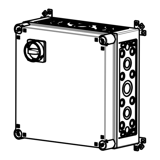
Technical data 2 Technical data Place of use outside EX zone Housing dimensions 375 x 375 x 188 Housing cover transparent Installation vertical Supply voltage (mains / motor voltage) 3 N~220-400 V, PE V AC (+/- 10%) 3~220-400 V, PE Max. -
Page 6: Components
Components 3 Components 3.1 Motor protection switch Motors for use in potentially explosive atmospheres (Ex) require protection against overload and short circuit. Overload protection is provided by a built-in motor protection switch (Q2). The motor protection switch is suitable for Ex-d/Ex-de and Ex-e motors. The protection is current-dependent and becomes effective when the motor is blocked. -
Page 7: Pass-Door / Slack-Rope Switch
Components 3.4 Pass-door / slack-rope switch The Zener barrier N2 is an associated device without galvanic isolation. This barrier is suitable for zones 1, 2 (gas) as well as 21, 22 (dust) and serves to evaluate a switch contact (pass-door / slack- rope switch). -
Page 8: Installation
Installation 4 Installation Before installation, the door control must be checked for transport or other damage. The base for attaching the door control must be level and free of vibrations. The door control must be easily accessible and be installed between 0.6 m and 1.7 m above the floor. Installation is only permissible in vertical mounting position. -
Page 9: Other Connections
Installation 4.3 Other connections Limit switch at drive unit Control device in door area Ceiling pull switch (optional) A latching switch to release the automatic closing mechanism (optional) The connection terminals are located in control circuits with 24 V DC. DANGER ... -
Page 10: Description Door Control Ts 971
Description door control TS 971 5 Description door control TS 971 5.1 Overview of control DES/ F1 = 1,6A t 24 V mains supply, external devices DES/ DES or NES limit switch socket Mains supply Micro-fuse 1.6 A time-lag Safety edge and... -
Page 11: Nes: Rapid Adjustment Of Final Limit Positions
Description door control TS 971 5.2 NES: Rapid adjustment of final limit positions 1. Check output rotating direction 2. Move to OPEN final limit position and adjust S3 OPEN limit switch 3. Move to CLOSE final limit position 5cm above the ground and adjust S5 pre-limit switch 4. -
Page 12: Control Programming
Control programming 6 Control programming 1. Start programming Note! Possible after rapid adjustment of final limit positions 2. Select menu item and confirm 3.a) Set and store functions 3.b) Set and store positions 4. Exit programming... -
Page 13: Door Operating Modes
Control programming 6.1 Table menu items Door operating modes Door operating mode OPEN Hold-to-run CLOSE Hold-to-run OPEN Self-hold CLOSE Hold-to-run OPEN Self-hold CLOSE Self-hold OPEN Self-hold CLOSE Self-hold, CLOSE hold-to-run release via external X5 control device OPEN Hold-to-run CLOSE Hold-to-run with active safety edge Output rotating direction Maintain output rotating direction Change output rotating direction... -
Page 14: Door Functions, Part 2
Control programming Door functions, Part 2 Automatic closing 0 to 240 seconds Extended photo cell function Cancel automatic closing and CLOSE command Vessel recognition Cancellation of automatic closing and CLOSE-command if photo cell activation duration > 1.5 seconds Reversing 0 = Off 1 to 10 safety-device activations Pull switch or radio receiver function X7 Type of impuls 1... -
Page 15: Door Functions, Part 3
Control programming Door functions, Part 3 Relay function on X20 Relay function on X21 Impuls contact for 1 second Permanent contact Red lamp, permanently lit during door movement OPEN final limit position Flashing for 3 seconds CLOSE final limit position Flashing for 3 seconds Red lamp, permanently lit during door movement OPEN final limit position... -
Page 16: Door Functions, Part 4
Control programming Door functions, Part 4 Intermediate open function All command inputs Input X7.2 and internal radio receiver Input X5.3 and OPEN push-button of control Safety functions Travel time monitoring (NES) 0 = Off 0 to 90 seconds Door safety switch function (Input X2.2) Slack-rope or pass-door switch Automatic opening... -
Page 17: Maintenance Cycle Counter
Control programming Maintenanc e cy cle counter Maintenance cycle counter Maintenance cycle preselection 01-99 corresponds to 1,000 to 99,000 cycles Cycles are counted down Reaction upon reaching "Zero" Status indication "CS" appears in turns with value set by menu item 8.5. Changeover to "Hold-to-run"... -
Page 18: Readout Of Data Memory
Number of activations of slack-rope, pass-door and crash switch Software version The software version of the control is displayed. Deleting / readout Deleting of all settings Activating GfA stick All settings are set to factory setting! Except for cycle counter... -
Page 19: Safety Devices
Safety devices 7 Safety devices 7.1 X2: Input, safety edge system 8k2 The door control automatically detects different safety edges to protect the closing movement of the gate wing. Note ▶ Connect safety edge systems in accordance with EN 12978! ▶... -
Page 20: Emergency Operation
Safety devices 7.2 EMERGENCY operation CAUTION ▶ For EMERGENCY operation, the door has to be checked (it has to be in a fault- free state) “Hold-to-run” door operating mode: The door must be fully visible from the operating point EMERGENCY operation allows for moving the door to a required position by bypassing faults with the signal transmission of the safety device. -
Page 21: Status Display
Status display 8 Status display Faults Display: "F" and code Code Fault description Fault causes and fault correction Terminals X2.1 – X2.2 are open. Check door safety switch. Slack-rope switch/Pass-door contact is open. Check whether the connection cable is connected. Open safety circuit (DES) Emergency manual operation has been Check emergency manual operation. -
Page 22: Faults
Status display Faults Display: "F" and code Code Fault description Fault causes and fault correction (NES) OPEN or CLOSE emergency stop switch Check OPEN/CLOSE emergency stop switch. reached. Check emergency manual operation. Emergency manual operation has been activated. Check drive unit for overload or stalling. Thermal protection of the motor has tripped Reset of control via menu item "9.5". -
Page 23: Commands
Status display Commands Display: "E" and code Code Command description An OPEN-command is present. Inputs X5.3, X7.2, internal radio system, UBS control device or UBS radio receiver A STOP command is present. Inputs X5.2, X7.2, internal radio system, UBS control device or UBS radio receiver or simultaneous OPEN and CLOSE commands A CLOSE command is present. - Page 24 Status display Status indications Status Description display Emergency operation is active or programming option is blocked. Flashing Teach in OPEN final limit position. Flashing Teach in CLOSE final limit position. Flashing UPWARDS travel active. Flashing CLOSING operation active. Flashing Stop between the set final limit positions. Stop at the OPEN final limit position.
-
Page 25: Explanation Of Symbols
Explanation of symbols 9 Explanation of symbols Symbol Explanation Prompt: Read installation instructions Prompt: Check Prompt: Note Prompt: Note the setting of the menu item below Factory setting of the menu item Factory setting of the menu item, value on the right Factory setting of the minimum limit, dependent on drive unit Factory setting of the maximum limit, dependent on drive unit Setting range... - Page 26 Explanation of symbols Symbol Explanation Prompt: Setting via OPEN/CLOSE built in push-button; Use OPEN push-button to increase value, CLOSE push-button to decrease value Prompt: Press stop button once via built in push-button Prompt: Save, press stop button once via built in push-button Prompt: Save, press stop button for three seconds via built in push-button Prompt: Reset the control,...
-
Page 27: Commissioning
Commissioning 10 Commissioning You need to check the following points before switching on: Correctly inserted lines Tightened seal plugs; sealed unused openings Connection space clean and free from foreign bodies (such as drilling chips) Connected wire-links or devices on terminals X2 / 11-12; X3 / 3.1-3.2 and N2 / 3-4 CAUTION ▶... -
Page 28: Maintenance / Annual Inspection
The door control may be repaired on site if no components of the explosion protection require replacement. Only complete components may be exchanged for original components. GfA assumes no liability whatsoever for damage resulting from the use of non-original spare parts and accessories. -
Page 29: Declaration Of Incorporation
Appendix II Part B Declaration of Conformity pursuant to EMC Directive 2014/30/EU GfA ELEKTROMATEN GmbH & Co. KG hereby declare that the product specified in the following complies with the above-mentioned EC Directive and is only intended for installation in a door.. -
Page 30: Characteristic Curves Of Motor Protection Switches
Characteristic curves of motor protection switches 14 Characteristic curves of motor protection switches... - Page 31 Characteristic curves of motor protection switches...
-
Page 32: Circuit Diagrams
Circuit diagrams 15 Circuit diagrams... - Page 33 Circuit diagrams...
- Page 34 Circuit diagrams...
- Page 35 Circuit diagrams...
- Page 36 Circuit diagrams...
- Page 37 Circuit diagrams...
- Page 38 Circuit diagrams...
- Page 39 Circuit diagrams...
-
Page 40: Parts List
Parts list 16 Parts list Item Quantity Type Designation Manufacturer Marking TS 971 Door control TS 971 G.M. D 1030D Switch device Exia 24 V DC International RL36-55-Ex/40b/116 Photo cell reflex Exia NAMUR Visolux A3/A4 CI44E-125 Housing 375x375x188 Eaton M3-CI44...
Need help?
Do you have a question about the TS 971 and is the answer not in the manual?
Questions and answers