
Related Manuals for GFA Elektromaten TS 956


Summary of Contents for GFA Elektromaten TS 956
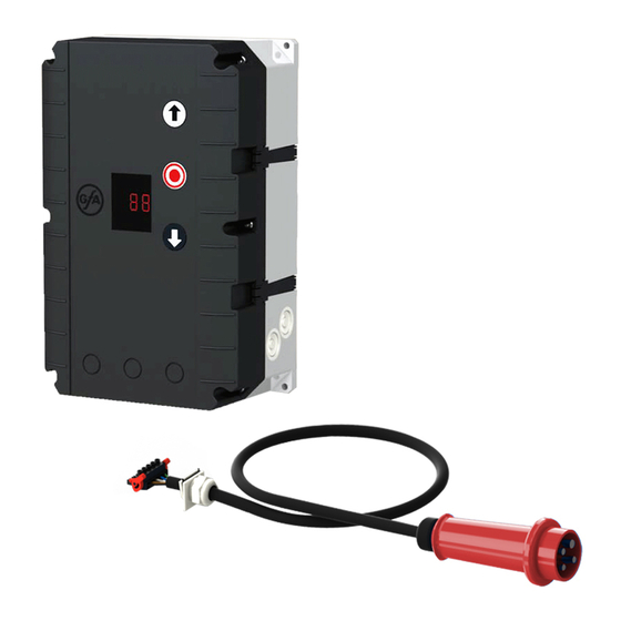
- Page 1 Electrical operating instructions Door control panel TS 956 Software 1.1 - (Design and functions subject to change) 51171301 - d 02.2013...
-
Page 2: Table Of Contents
OPERATING INSTRUCTIONS Page SAFETY DIRECTIONS ....................4 INSTALLATION ADVICE ....................6 INSTALLATION OVERVIEW ..................7 ENCLOSURE INSTALLATION ..................8 CONNECTING THE CONTROL AND THE ELEKTROMATEN ® ............LIMIT SWITCH CONNECTION ..................9 Plug - in system ......................9 Terminal version (until year 1997) ................10 MAINS SUPPLY ......................11 MOTOR CONNECTION (internal wiring) .............. - Page 3 Page FUNCTION DESCRIPTION ..................18 Internal push button / Three push button / Key switch X5 .........18 Fully closed control .....................18 Potential free changeover contact X9 ............... 19 Maintenance cycle counter ..................19 Short circuit / overload monitor ................... 19 OPERATING STATUS DISPLAY .................. 20 TECHNICAL DATA......................
-
Page 4: Operating Instructions
SAFETY DIRECTIONS Basic Directions This control has been built in accordance with EN 12453 Industrial, commercial and garage doors and gates - Safety in use of power operated doors - Requirements; and left the factory in perfect condition from the point of view of safety. To maintain this condition and to ensure safe operation, the user must observe all the directions and warnings contained in these operating instructions. - Page 5 SAFETY DIRECTIONS Explanation of warnings These operating instructions contain directions which are important for using the ELEKTRO- ® MATEN appropriately and safely. The individual directions have the following meaning: DANGER This indicates danger to the life and health of the user if the appropriate precautions are not taken.
-
Page 6: Installation Advice
INSTALLATION ADVICE After the ELEKTROMATEN ® is fitted we recommend the following procedure to rapidly reach a fully functioning door. • Installation Enclosure installation page 8 • Installation Wiring the Drive to the Control page 8 LIMIT SWITCH CONNECTION Plug - in system page 9 LIMIT SWITCH CONNECTION Terminal version (until year 1997) -
Page 7: Installation Overview
INSTALLATION OVERVIEW Important! Using the connection cable out side the building is not permitted. Connection cable ELEKTROMAT ® Motor and mechanical limits NES Spiral cable for pass-door slack-wire switch Mains supply Three push button Emergency stop Number of cores in the cable Page 7... -
Page 8: Enclosure Installation
ENCLOSURE INSTALLATION Before mounting the enclosure, the surface has to be checked for flatness, slope and freedom from vibrations. Mounting must be vertical. It is important that the door can be clearly seen from the position of the control through-out its travel. ®... -
Page 9: Limit Switch Connection
LIMIT SWITCH CONNECTION Plug - in system Page 9... -
Page 10: Terminal Version (Until Year 1997)
LIMIT SWITCH CONNECTION Terminal version (until year 1997) Page 10... -
Page 11: Mains Supply
MAINS SUPPLY DANGER! To the life and health thru electric shock. Before mounting the mains supply must be switched OFF. Important note! The bridge must be fitted into the right terminal otherwise the print could be destroyed. External fuse! Control must be saved against short circuit and overload by an external fuse, max. -
Page 12: Motor Connection (Internal Wiring)
MOTOR CONNECTION (internal wiring) Three-phase 3 x400 V AC, N, PE Three-phase 3 x230 V AC, PE Star connection Delta connection Important note! For 3x400V AC PE no neutral, the brake rectifier must be connected between terminal V and star- point terminal. -
Page 13: Limit Switch - Adjustment
LIMIT SWITCH - ADJUSTMENT After checking the phase rotation, the limit switches must be adjusted in the following steps. When open and close position limits have been set the safety limits are automatically pre-adjusted. Eventually fine adjustment could be required. Please see Mechanical Operating Instruction. -
Page 14: Hardware Overview
HARDWARE OVERVIEW Description Print: X1 Mains supply Selector switch external supply 230V 7-segment display 1.9 = L1 fused with F1 = 1A MOT Motor connection 1.8 = N NES Mechanical limit connection (only with 3 x 400V, N, PE und 1 x 230V, N, PE) Internal push button Pass-door plug X3 Emergency push button... -
Page 15: Wiring Diagram
WIRING DIAGRAM Terminal box Bridge spiral plug-in cable bridge passdoor / slack wire switch contact N L1 L1 fused via Emergency F1 = 1At stop button Open Open / Close Stop Stop Close Three push button Key switch with station stop button Open / Close... -
Page 16: Control Programming
CONTROL PROGRAMMING Enter programming Mode Press selector switch for 3 sec. until display = 00 Chose program and confirm Turn selector press selector Adjustment Functionen Turn selector Memorise Functionen Press selector further adjustments Exit programming Turn selector until display = 00 Press selector Page 16... -
Page 17: Operating Mode
CONTROL PROGRAMMING Adjustment Choose program and Memorise confirm Operating mode Press Dead man OPEN Door function selector Dead man CLOSE Self-hold OPEN Dead man CLOSE fully closed control Functions Relay function Press selector Switch contact impulse signal Switch contact continuous Maintenance cycle counter Counter adjustment 01-99 correspond from 1.000 up to... -
Page 18: Safety Devices
SAFETY DEVICES Mounting the spiral cable A bush is provided on both sides of the control box for mounting the spiral cable. Push the plugs through, into the enclosure until there is sufficient cable to allow the plug to be connected to the board. If passdoor / slack wire switch contact exists, remove bridge at terminal ST and ST+ in the terminal box. -
Page 19: Potential Free Changeover Contact X9
FUNCTION DESCRIPTION Potential free changeover contact In menu 2.5 this contact is able to work for several functions. Important note! It is only possible to work with one adjusted function. For functioning as a switching contact, impulse or continuous, the switching position must be adjusted by limit switch S6. -
Page 20: Operating Status Display
OPERATING STATUS DISPLAY The control TS956 can display up to threedifferent status conditions one after another. Each status is displayed with a letter and a number. The letter and the number are flashing alternately, thereby the control differentiates between a FAULT = F and a command = E. Report Description Measure to solve the problem... - Page 21 LIFETIME / DOORCYKLES The GfA control panels working with electro mechanical contactor boards. Contactor boards having generally a limited life time; this depends on the switched power of ELEKTROMATEN in use and the amount of switching cycles. Therefore we recommend a ®...
-
Page 22: Technical Data
TECHNICAL DATA Housing Dimensions 190mm x 300mm x 115mm (B x H x T) Mounting vertical ELEKTROMATEN ® Supply Three-phase 3 x 230 / 400V AC ± 5%, 50...60Hz Single-phase 1 x 230V ± 5%, 50...60Hz Power max. at 3 x 400V AC, max. 3kW Control supply via L1,L2 400V AC or 230V AC + - 10%, 50-...60Hz, voltage changing with bridge to 3- pol terminal,... -
Page 23: Declaration Of Incorporation
EMC Directive 2004/108/EC www.gfa-elektromaten.de We, the GfA - Gesellschaft für Antriebstechnik hereby declare that the following products are conform with the above EC Guidelines and are only intended for installation in door equipment. Door control panel TS 956... -
Page 24: Function Overview
FUNCTION OVERVIEW • ® Conrol panel for ELEKTROMATEN up to. 3 kW at 400V / 3~ phase with mechanical limits • 7- Segment led display showing - Programming the control panel - Displays Command - / Info- / Fault • Mains supply - 400V / 3~ with and without Neutral - 230V / 3~...
Need help?
Do you have a question about the Elektromaten TS 956 and is the answer not in the manual?
Questions and answers