Table of Contents
Advertisement
USER GUIDE
NI USB-6001/6002/6003
Low-Cost DAQ USB Device
This user guide describes how to use the National Instruments USB-6001/6002/6003 data
acquisition (DAQ) devices. For device specifications, go to
device name.
The NI USB-6001/6002/6003 is a full-speed USB device that provides eight single-ended
analog input (AI) channels, which may also be configured as four differential channels. It also
includes two analog output (AO) channels, 13 digital input/output (DIO) channels, and a 32-bit
counter.
Table 1. Differences Between the NI USB-6001, NI USB-6002, and NI USB-6003
Feature
Analog-to-digital
converter (ADC)
Resolution
Maximum Sample
Rate (aggregate)
DAC Resolution
Absolute Accuracy,
Typical, at full scale
Français
Deutsch
ni.com/manuals
NI USB-6001
Analog Input
14-bit
20 kS/s
Analog Output
14-bit
9.1 mV
ni.com/manuals
NI USB-6002
16-bit
50 kS/s
16-bit
8.6 mV
and search by
NI USB-6003
16-bit
100 kS/s
16-bit
8.6 mV
Advertisement
Table of Contents

Related Manuals for National Instruments USB-6001


Summary of Contents for National Instruments USB-6001
- Page 1 NI USB-6001/6002/6003 Low-Cost DAQ USB Device Français Deutsch ni.com/manuals This user guide describes how to use the National Instruments USB-6001/6002/6003 data acquisition (DAQ) devices. For device specifications, go to and search by ni.com/manuals device name. The NI USB-6001/6002/6003 is a full-speed USB device that provides eight single-ended analog input (AI) channels, which may also be configured as four differential channels.
-
Page 2: Safety Guidelines
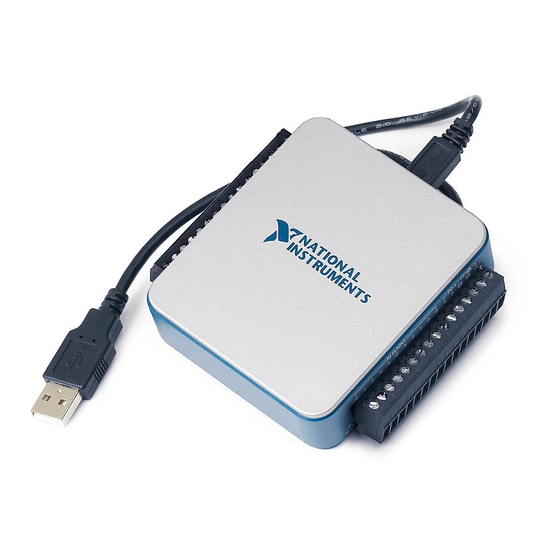
Figure 1. NI USB-6001/6002/6003 Top and Side Views Screw Terminal Connector Plug LED Indicator Micro-B USB Connector Safety Guidelines Operate the NI DAQ device only as described in this document. Caution Refer to the NI USB-6001/6002/6003 Safety, Environmental, and Regulatory Information document included with your kit for important safety and electromagnetic compatibility information. -
Page 3: Electromagnetic Compatibility Guidelines
Furthermore, any modifications to the product not expressly approved by National Instruments could void your authority to operate it under your local regulatory rules. -
Page 4: Installing The Software
Setting Up the NI USB-6001/6002/6003 Complete the following steps to get started with the NI USB-6001/6002/6003. Installing the Software Install the application software (if applicable), as described in the installation instructions that accompany your software. Install NI-DAQmx. NI USB-6001/6002/6003 devices are supported by NI-DAQmx 9.9 and later. -
Page 5: Verifying The Installation
NI-DAQmx driver software includes example programs to help you get started programming with the NI USB-6001/6002/6003. You can modify example code and save it in an application, use examples to develop a new application, or add example code to an existing application. -
Page 6: Ansi C Without Ni Application Software
Measurement Studio from the Filtered By drop-down list. To get to the same help topics from within Visual Studio 2010, go to Help»View Help and select NI Measurement Studio Help from the Related Links section. 6 | ni.com | NI USB-6001/6002/6003 User Guide... -
Page 7: Block Diagram
Control Full Connector Logic Speed (Micro-B) Interface AI 0 Analog Input AI 7 AI GND 80 MHz Clock AO 0 Analog Output AO 1 AO GND 16-Position Screw Terminal Plug NI USB-6001/6002/6003 User Guide | © National Instruments | 7... -
Page 8: Led Indicator
Screw Terminal Connector Plugs The NI USB-6001/6002/6003 ships with two detachable screw terminal connector plugs: one for analog signals and one for digital signals. These screw terminal connectors provide 16 connections that use 0.08 to 1.31 mm (28 to 16 AWG). -
Page 9: Pinout And Signal Descriptions
0. The following signal pairs also form differential input channels: AI <1,5>, AI <2, 6>, and AI <3, 7>. Refer to the Analog Input section for more information. NI USB-6001/6002/6003 User Guide | © National Instruments | 9... - Page 10 Digital Ground—The reference point for digital signals. +5 V D GND Output +5 V Power Source—Provides +5 V power up to 150 mA. Refer to the +5 V Power Source section for more information. 10 | ni.com | NI USB-6001/6002/6003 User Guide...
-
Page 11: Analog Input
Analog Input The NI USB-6001/6002/6003 has eight analog input channels that you can use for four differential analog input measurements or eight single-ended analog input measurements. Figure 5 shows the analog input circuitry of the NI DAQ device. Figure 5. NI USB-6001/6002/6003 Analog Input Circuitry... -
Page 12: Analog Input Modes
AI+ terminal, and the negative lead to the AI- terminal. Figure 6. Connecting a Differential Voltage Signal Voltage DAQ Device Source AI– Figure 7. Example of a Differential ± 10 V Measurement AI 1 AI 5 Result –5 –10 12 | ni.com | NI USB-6001/6002/6003 User Guide... -
Page 13: Taking Referenced Single-Ended Measurements
AI terminal, and the ground signal to a AI GND terminal, as shown in Figure 8. Figure 8. Connecting a Referenced Single-Ended Voltage Signal Voltage DAQ Device Source AI GND NI USB-6001/6002/6003 User Guide | © National Instruments | 13... - Page 14 Refer to the Taking Differential Measurements section for descriptions of the RSE and DIFF modes and software considerations. † Refer to the Ground-Referenced Signal Sources section for more information. 14 | ni.com | NI USB-6001/6002/6003 User Guide...
-
Page 15: When To Use Differential Connections With Floating Signal Sources
Magnetic coupling is proportional to the area between the two signal conductors. Electrical coupling is a function of how much the electric field differs between the two conductors. Refer to the Taking Referenced Single-Ended Measurements section for more information about RSE connections. NI USB-6001/6002/6003 User Guide | © National Instruments | 15... -
Page 16: When To Use Referenced Single-Ended (Rse) Connections With Ground-Referenced Signal Sources
As shown in the bottom right cell of Table 6, there can be a potential difference between AI GND and the ground of the sensor. In RSE mode, this ground loop causes measurement errors. 16 | ni.com | NI USB-6001/6002/6003 User Guide... -
Page 17: Input Range
+10.5 V and -10.5 V or may rail to ±10.5 V. This behavior is normal and does not affect the measurement when a signal is connected. For more information about field and wiring noise considerations for analog signals, go to and enter Info Code ni.com/info rdfwn3 NI USB-6001/6002/6003 User Guide | © National Instruments | 17... -
Page 18: Multichannel Scanning Considerations
You can configure PFI 0 or PFI 1 as the AI Start Trigger for analog input tasks. Refer to the Using PFI to Trigger an Analog Input Acquisition section for more information. Analog Output Figure 11 shows the analog output circuitry of the NI USB-6001/6002/6003. Figure 11. Analog Output Circuitry AO Start Trigger AO Sampling Clock... -
Page 19: Connecting Analog Output Signals
The AO exhibits a short glitch when the device is powered on and when the NI DAQ dev ice exits suspend mode. After power-up, the AO is reset to 0 V. AO Range The AO range is ± 10 V. NI USB-6001/6002/6003 User Guide | © National Instruments | 19... -
Page 20: Minimizing Glitches On The Output Signal
You can configure PFI 1 or PFI 0 as the AO Start Trigger for analog output tasks. Refer to the Using PFI to Trigger an Analog Output Generation section for more information. 20 | ni.com | NI USB-6001/6002/6003 User Guide... -
Page 21: Power-On States
Digital I/O The NI USB-6001/6002/6003 has 13 digital lines: P0.<0..7>, P1. <0..3>, and P2.0. D GND is the ground-reference signal for digital I/O. You can individually program each line as input or output. All digital input and digital output updates and samples are software-timed. -
Page 22: Source/Sink Information
If you configure a DIO line as an output, understand the current requirements of the load connected to these signals. Do not exceed the specified current output limits of the NI DAQ device. National Instruments has several signal conditioning solutions for digital applications requiring high-current drive. -
Page 23: Power Source
To do this, configure the AO Start Trigger source to be PFI 0 or PFI 1 and specify either rising- or falling-edge. +5 V Power Source Figure 15 shows the +5 V power source circuitry of the NI USB-6001/6002/6003. Figure 15. +5 V Power Source Circuitry To USB... -
Page 24: Connecting The Load
NI USB-6001/6002/6003 The NI USB-6001/6002/6003 Quick Start packaged with your NI DAQ device describes how to install the device and confirm that your device is operating properly. The NI USB-6001 Specifications, NI USB-6002 Specifications, and NI USB-6003 Specifications are available for download from ni.com/manuals... -
Page 25: Measurement Studio
NI MAX or from within Visual Studio. You can use Measurement Studio to generate the configuration code based on your task or channel. Refer to the DAQ Assistant Help for additional information about generating code. NI USB-6001/6002/6003 User Guide | © National Instruments | 25... - Page 26 Select Start»All Programs»National Instruments»NI-DAQmx»NI-DAQmx Help. The NI-DAQmx C Reference Help describes the NI-DAQmx Library functions, which you can use with National Instruments data acquisition devices to develop instrumentation, acquisition, and control applications. Select Start»All Programs»National Instruments»NI-DAQmx» Text-Based Code Support»NI-DAQmx C Reference Help.
-
Page 27: Training Courses
NI product. Refer to the Export Compliance Information at ni.com/legal/export-compliance for the National Instruments global trade compliance policy and how to obtain relevant HTS codes, ECCNs, and other import/export data. NI MAKES NO EXPRESS OR IMPLIED WARRANTIES AS TO THE ACCURACY OF THE INFORMATION CONTAINED HEREIN AND SHALL NOT BE LIABLE FOR ANY ERRORS. -
Page 28: Specifications
SPECIFICATIONS NI USB-6002 Low-Cost DAQ USB Device Analog Input... - Page 29 Analog Output 2 | ni.com | NI USB-6002 Specifications...
- Page 30 Timebase Note Digital I/O NI USB-6002 Specifications | © National Instruments | 3...
-
Page 31: Digital Input
Digital Input Caution Digital Output (Active Drive) 4 | ni.com | NI USB-6002 Specifications... - Page 32 Digital Output (Open Collector) Note Counter NI USB-6002 Specifications | © National Instruments | 5...
-
Page 33: Bus Interface
+5 V Power Source Bus Interface Physical Characteristics 6 | ni.com | NI USB-6002 Specifications... - Page 34 Figure 1. NI USB-6002 Dimensions 3.67 in (93.2 mm) 0.93 in. 2.97 in. (23.6 mm) (75.4 mm) 3.40 in. (86.2 mm) Environmental NI USB-6002 Specifications | © National Instruments | 7...
-
Page 35: Electromagnetic Compatibility
Safety Note Electromagnetic Compatibility Note Note Note 8 | ni.com | NI USB-6002 Specifications... -
Page 36: Online Product Certification
CE Compliance Online Product Certification Environmental Management Waste Electrical and Electronic Equipment (WEEE) EU Customers RoHS NI USB-6002 Specifications | © National Instruments | 9... -
Page 37: Device Pinout
Other product and company names mentioned herein are trademarks or trade names of their respective companies. For patents covering National Instruments products/technology, refer to the appropriate location: Help Patents in your software, the file on your media, or the National Instruments Patent Notice at .
Need help?
Do you have a question about the USB-6001 and is the answer not in the manual?
Questions and answers