Advertisement
Quick Links
QUICK START GUIDE FOR DEMONSTRATION CIRCUIT 1090A
PUSH BUTTON ON/OFF CONTROLLER WITH MICROPROCESSOR INTERRUPT
DESCRIPTION
Demonstration Circuit 1090A features the LTC2954-2,
a push button ON/OFF controller that manages system
power via a push button interface. An enable output
toggles system power while an interrupt output pro-
vides a debounced push button status. The interrupt
output can be used in menu driven applications to re-
quest a system power down. A power kill input allows
a microprocessor or system to reset the enable out-
put, effectively powering down the system. Independ-
ently adjustable On and Off timers allow dependable
push button control of the enable output and resis-
tance to accidental toggling of system power.
QUICK START PROCEDURE
Demonstration circuit 1090A is easy to set up to evalu-
ate the performance of the LTC2954-2:
Place jumpers in the following positions:
1.
JP1
CON
JP2
CPD
JP3
UNTIE
The LTC2954 operates over a wide 2.7V to 26.4V
input voltage range to accommodate a wide variety
of input power supplies. Very low quiescent current
(6µA typical) makes the LTC2954 ideally suited for
battery powered applications. Two versions of the
part are available to accommodate either positive or
negative enable polarities. The inversion of /EN of
the LTC2954-2 is found in the LTC2954-1
Design files for this circuit board are available.
Call the LTC factory
LTC is a trademark of Linear Technology Corporation
Connect the input power supply of 2.7V to 26.4V
2.
across VIN and GND or a 9V battery to the battery
connector.
Push and hold the push button once to turn on the
3.
green LED.
Push and hold again on the push button to turn off
4.
the green LED.
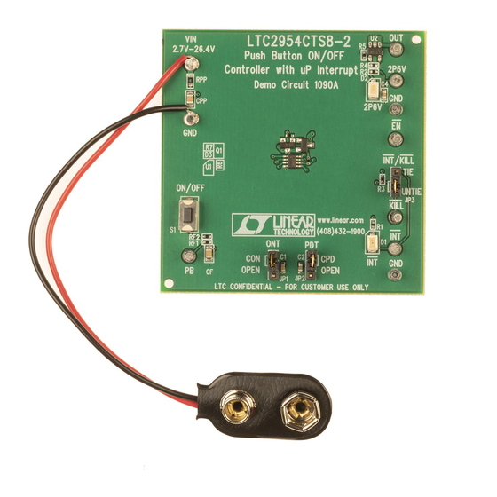
Figure 1. DC1090A Example Setup
LTC2954-2
.
1
Advertisement

Subscribe to Our Youtube Channel
Related Manuals for Linear Technology DC 1090A


Summary of Contents for Linear Technology DC 1090A
- Page 1 Call the LTC factory push button control of the enable output and resis- tance to accidental toggling of system power. LTC is a trademark of Linear Technology Corporation QUICK START PROCEDURE Demonstration circuit 1090A is easy to set up to evalu- Connect the input power supply of 2.7V to 26.4V...
-
Page 2: Operating Principles
QUICK START GUIDE FOR DEMONSTRATION CIRCUIT 1090A PUSH BUTTON ON/OFF CONTROLLER WITH MICROPROCESSOR INTERRUPT OPERATING PRINCIPLES On the DC1090A, a push button switch shorts the /PB By tying /KILL to /INT through JP3, /KILL is forced low pin to ground which in turn sets the /EN pin low. during the /INT blanking time and thus forces a turn Shorting /PB to ground a second time and holding off. - Page 3 QUICK START GUIDE FOR DEMONSTRATION CIRCUIT 1090A PUSH BUTTON ON/OFF CONTROLLER WITH MICROPROCESSOR INTERRUPT Figure 2. Push Button Turn On/Off with ONT and PDT Open (time scale at 10ms/div) Figure 3. Push Button Turn On/Off with Capacitors on ONT and PDT...
- Page 4 QUICK START GUIDE FOR DEMONSTRATION CIRCUIT 1090A PUSH BUTTON ON/OFF CONTROLLER WITH MICROPROCESSOR INTERRUPT...
- Page 5 Mouser Electronics Authorized Distributor Click to View Pricing, Inventory, Delivery & Lifecycle Information: Analog Devices Inc. DC1090A...
Need help?
Do you have a question about the DC 1090A and is the answer not in the manual?
Questions and answers