Table of Contents
Advertisement
Quick Links
Advertisement
Chapters
Table of Contents

Subscribe to Our Youtube Channel
Related Manuals for wtw TresCon


Summary of Contents for wtw TresCon
- Page 1 OPERATING MANUAL ba43108e10 05/2017 TresCon TERMINAL...
- Page 2 TresCon © Copyright 2017 Xylem Analytics Germany GmbH Printed in Germany. ba43108e10 05/2017...
-
Page 3: Table Of Contents
Prerequisites for installation ..... 3-2 Installing the TresCon ......3-3 Further connections (optional) . - Page 4 List of contents TresCon Initial commissioning ......4-1 Checklist for initial commissioning ....4-1 Switching on .
- Page 5 5.7.5 Report ....... 5-88 5.7.6 TresCon Info ......5-91 5.7.7 Date and time.
- Page 6 List of contents TresCon 0 - 4 ba43108e10 05/2017...
-
Page 7: Overview
Structure and function of TresCon Please read the following section 1.1 A BOUT THIS OPERATING MANUAL before starting to work with the TresCon. You will discover how to rapidly find the information that you require. About this operating manual This operating manual has a modular structure. - Page 8 Overview TresCon Lists Each part of the operating manual contains the following lists: List of contents Index The present section additionally contains the list of abbreviations. These lists enable you to quickly find the correct information. Note...
-
Page 9: General Information
– TresCon NH4-N for measuring ammonium - nitrogen – TresCon NO2-N for measuring nitrite - nitrogen – TresCon NOx-N for measuring nitrate/nitrite - nitrogen – TresCon NOx-N/SAK for measuring nitrate/nitrite - nitrogen and the spectral absorption coefficient – TresCon PO4-P for measuring orthophosphate –... - Page 10 Overview TresCon Software The software-related task distribution of controller and analyzer modules is reflected in the menu structure: Menu Menu of the central unit (controller) Measuring mode Module 1 Module 2 Menu Selected module (here 1) Fig. 1-2 Software structure...
-
Page 11: Field Of Application/Features
ATV specification M269 The TresCon fulfills all the points of the guidelines specified in the "Requirements of on-line process analysis instruments for N and P" in the ATV specification, M269: High availability of the systems to ensure continuous operation of the wastewater treatment plant, ... - Page 12 Overview TresCon Controller The controller is the operating unit of the instrument. It is equipped with a planar display that also enables the graphical representation of measured values such as daily and weekly load diagrams. The operation of all the components is menu-driven via the display and keys in the dialog system.
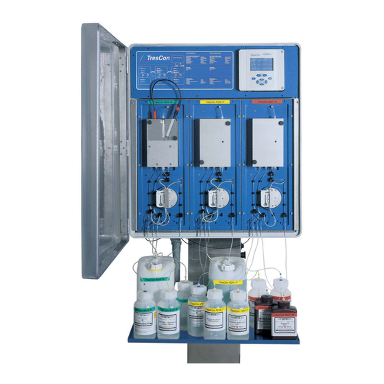
- Page 13 TresCon Overview TresCon N0x-N Fig. 1-4 Single analyzer module, e.g. TresCon NOx-N Reagents The reagent containers and standards stand on a tray. The containers are color coded. The colors correspond to the color of the individual analyzer modules. This enables the containers to be uniquely identified.
- Page 14 Overview TresCon View of the instrument Fig. 1-5 Overall view of the analyzer 1 - 8 ba43108e10 05/2017...
-
Page 15: Output Of Measured Values
TresCon Overview 1.2.3 Output of measured values Altogether, the analyzer provides the following options to record, store and output the measured values and messages: Display Display Measuring mode In normal operation, the current measured values of the individual analyzer modules are displayed on the screen of the controller. - Page 16 Overview TresCon 1 - 10 ba43108e10 05/2017...
-
Page 17: Safety
TresCon Safety Safety This chapter contains basic instructions that you must follow during the commissioning, operation and maintenance of the instrument. Consequently, the user must read this chapter before working with the instrument. The operating manual must always be available within the vicinity of the instrument. - Page 18 If you are in any doubt, please contact the supplier of the instrument. Operating personnel TresCon was developed for use in wastewater treatment plants. We assume that, as a result of their professional training and experience, the operators will know the necessary safety precautions to take when handling chemicals.
-
Page 19: Use Of Symbols
TresCon Safety Use of symbols Warning This symbol indicates danger to life and limb. It is essential to read and follow these instructions! Caution This symbol indicates danger of material damage that could occur as a result of faulty operation. It is essential to read and follow these... -
Page 20: Response After A Power Failure
Stop, Service, Stop Parameterization Environmental protection/Disposal WTW products are designed to take into account the recycling and disposal of the product at the end of its lifetime as a constituent part of product development. Our factory standards lay down stringent requirements. -
Page 21: Installation
Fig. 3-1 Schematic diagram: 1 analyzer module Maximum configuration The TresCon can be flexibly configured: A maximum of three analyzer modules can be operated simultaneously and independently of one another; up to three different samples can be analyzed or one/two sample(s) with up to three different modules. -
Page 22: Scope Of Delivery
Mounting stand with integrated power unit and tray Fixing elements for wall mounting Power cable 2 m TresCon operating manual for terminal and module (depending on the scope of the order) TresCon basic instrument with analyzer modules (depending on the scope of the order) ... -
Page 23: Installing The Trescon
The consumption of reagents depends on the intervals selected for measuring and cleaning. For more detailed information, please refer to the operating manual of the analyzer module. Installing the TresCon Caution The mounting, installation and setting up of the instrument must only be performed by trained specialist personnel after they have carefully studied this operating manual. - Page 24 Installation TresCon Wall mounting Please follow this sequence when mounting the individual components. Note The mounting stand stands on the floor so that the wall supports merely prevent it falling over! Caution When selecting the fixing elements (screws, dowels etc.) to hang up...
- Page 25 TresCon Installation Mounting stand Fig. 3-5 Attaching the mounting stand (diagonal view from behind) Screw the mounting stand to the wall supports using the socket head cap screws supplied. ba43108e10 05/2017 3 - 5...
- Page 26 Installation TresCon Mounting with For freestanding mounting use the stand elements, article no. 81001 stand feet (optional) (accessory, not contained in the scope of delivery) Screw the feet to the mounting stand according to Fig. 3-6. 140 mm 1050 mm Fig.
- Page 27 Note When using the TresCon with samples that are heavily loaded with sediment we recommend to use the overflow vessel with controllable valve instead of the normal overflow vessel (see section 3.5 O...
- Page 28 Installation TresCon Configuration Number of overflow vessels 1 catch location, 1-3 analyzer 1 x triple modules 2 or 3 catch locations, 2 or 3 single ones each with 1 analyzer module 2 catch locations per analyzer see section 3.6.1 I...
- Page 29 TresCon Installation Mounting of the TresCon Attach the TresCon to the mounting stand by the holding lugs (see Fig. 3-9). Caution This activity must be performed by at least 2 people! Ensure the holding lugs are in the correct position! Fig.
- Page 30 26.32 mg/l N03-N Ablauf Kläranlage N03-N Ablauf Kläranlage N03-N I3= 8 mA I3= 8 mA K K K 7 7 4 4 TresCon N0x-N TresCon P04-P TresCon N02-N Fig. 3-10 Screws of the mounting frame 3 - 10 ba43108e10 05/2017...
- Page 31 TresCon Installation Attach the TresCon to the inside of the mounting stand using the socket-head cap screws supplied (A, B, C) according to Fig. 3-11. Fig. 3-11 Mounting frame tilted forward Swing back the frame and firmly tighten the two fixing screws (B) (see Fig.
- Page 32 7 7 4 4 Fig. 3-12 Removing the cover plate Feed the power cord of the mounting stand from the back through the PG of the TresCon according to Fig. 3-13. Power cord Fig. 3-13 Mounting the feed line 3 - 12...
- Page 33 TresCon Installation Connect the 4 wires to the terminals of the connection board of the TresCon according to Fig. 3-14. Follow the label on the cover of the connecting board and the labeling of the wires when doing this. Note The number is printed on the insulation of the individual wires.
- Page 34 Installation TresCon Connecting the The type and number of overflow vessels used depends on the permeate feed configuration of the analyzer. A set (overflow vessel, drain pipe with Y- piece and connection piece) is contained in the scope of delivery.
- Page 35 TresCon Installation Connecting the outlet of Attach the angle piece supplied to the outlet of the TresCon the TresCon according to Fig. 3-16. Outlet tube Ø 40 mm Fig. 3-16 Mounting the drain pipe Connect an outlet pipe with a nominal diameter of 40 mm and feed it to a suitable, pressure-free drain.
- Page 36 Installation TresCon Plug the connection piece into the opening of the HT-Y piece according to Fig. 3-17. Outlet connection piece Fig. 3-17 Assembling the connection piece Plug the black outlet tubing (1 piece per overflow vessel, = 6.4 mm) to the center fitting on the overflow vessel (see Fig.
- Page 37 TresCon Installation Overflow vessel Permeate feed Ventilation (e.g. PurCon) Outlet Fig. 3-18 Connecting the outlet tubes Note The ventilation fitting must not be blocked. Tray outlet Mount a canister with at least 10 l capacity to the outlet pipe of the tray or to the outlet pipe of the drainage system (use a syphon).
-
Page 38: Further Connections (Optional)
- as an alternative to this, the RS232 cable can be connected to the terminal strip – One D-Sub male connector on the terminal strip board The connections are on the terminal strip in the TresCon enclosure. Relays Terminals... - Page 39 This could result in life threatening electric shock when working with the TresCon. Always cut off any wires that are not in use as closely as possible to the cable gland.
-
Page 40: Connecting Lines To The Terminal Strip
Installation TresCon Connecting lines to the Remove the cover plate by opening the screws (C). terminal strip Caution The cover plate may only be opened by a qualified electrician. Operation without a properly mounted cover plate is not allowed. TresCon <<Stop... - Page 41 TresCon Installation Lead the cable(s) to the terminal strip (Fig. 3-19). When doing so, separate voltages subject to the danger of physical contact from Safety Extra Low Voltage SELV: – Insert all voltages subject to the danger of physical contact...
-
Page 42: Relays
Installation TresCon 3.4.3 Relays Warning If external electrical circuits that are subject to the danger of physical contact are incorrectly connected to the relay contacts, there may be a danger of life threatening electric shock. Electrical circuits are regarded to be subject to the danger of physical contact when there are voltages higher than the Safety Extra Low Voltage (SELV). -
Page 43: Valve Control
TresCon Installation RCD protective circuit Example of the circuit: I: Highest switching power at the relay U: Maximum Contact switching voltage : Load current Load I Fig. 3-22 RCD protective circuit for inductive load Component dimensioning: · ⋅ 0 1μF I... -
Page 44: Recorder Outputs
Installation TresCon 3.4.5 Recorder outputs Terminal strip Assignment Recorders Fig. 3-24 Terminals of the recorder outputs Note The setting of the recorder is described in 5.4 R SECTION ECORDER from 5-50. FUNCTION PAGE 3.4.6 Digital interfaces: General information The analyzer has two serial interfaces: ... -
Page 45: Rs485
TresCon Installation 3.4.7 RS485 This interface can be used in either Slave or Master mode. Terminal strip Assignment RS485 Fig. 3-26 Terminals of the RS485 interface Note The setting of the interface parameters is described in section 5.5.2 RS485 (S and section 5.5.3 RS485... - Page 46 Installation TresCon Terminal strip Assignment RS232 GND TxD 2: RxD 3: TxD 5: GND 6 7 8 7: RTS 8: CTS RS232 D-SUB Fig. 3-27 Connections of the V24/RS232 interface Note The terminal strip and the D-SUB plug are wired with one another (switched in parallel).
-
Page 47: Modem On Rs232
Hardware support The TresCon supports the Hayes standard. All modems that support this standard can be used. A rudimentary command set is used so that it is unnecessary to adjust to the special commands of different manufacturers. -
Page 48: Option: Overflow Vessel With Controllable Valve
Application The TC/ÜB V overflow vessel with controllable valve is available as an accessory and is not contained in the TresCon scope of delivery. It was developed for the following applications: Use of the TresCon when the sample is heavily loaded with sediments but without sample filtration: TresCon controls the valve. - Page 49 TresCon Installation Triple overflow vessel Scope of delivery, TC/ÜB V Magnetic valve with control line (1.65 m) Mounting plate 2 fixing screws for overflow vessel (countersunk screws, M5 x 8) 2 fixing screws for magnetic valve (countersunk screws, M4 x 20) ...
-
Page 50: Installing The Overflow Vessel With Valve
The overflow vessel with valve is screwed to the mounting stand of the TresCon instead of the series overflow vessel. 2 further overflow vessels can be fixed to the mounting plate so that the TresCon can be operated with several sample catch locations. - Page 51 TresCon Installation Assembling the Switch off the TresCon. component at the TresCon Remove the overflow vessels from the mounting location. Thread for additional overflow vessels Fig. 3-30 Mounting plate with overflow vessel and valve Select the suitable drilled holes for the assembly depending on how much room is required (position 1 or 2, Fig.
- Page 52 Installation TresCon Mounting stand Fig. 3-31 Fixing the overflow vessel with valve at the mounting stand Preparing the outlet For the outlet tubing of the valve, another access to the outlet pipe is required. For this purpose, the following items are contained in the scope of delivery: ...
- Page 53 TresCon Installation Screw the fitting for the valve outlet tubing into the connection piece. ba43108e10 05/2017 3 - 33...
- Page 54 Installation TresCon Using the blind plugs, close the other 2 inlets of the connection piece. Plug the connection piece into the opening of the HT-Y piece. Connecting the valve Shorten the outlet tubing (ID = 9.5 mm) of the valve to the outlet tubing correct length.
- Page 55 TresCon Installation Connecting the overflow Shorten the outlet tubing for the overflow vessel ( = 6.4 mm) vessel outlet tubing to the correct length. The tubing must reach from the second fitting of the overflow vessel to the connection piece of the serial HT-Y piece.
- Page 56 Installation TresCon Electrical connection The control line for the valve is connected according to section 3.4 F ). The terminals for the valve URTHER CONNECTIONS OPTIONAL control are described in section 3.4.4 V . To lay the ALVE CONTROL control line, use the adhesive cable holders supplied.
-
Page 57: Maintenance Of The Overflow Vessel With Valve
3.5.3 Maintenance of the overflow vessel with valve The overflow vessel has to be cleaned regularly as follows: Procedure Open the outlet valve: – In case of control by the TresCon proceed according to section 6.1.2 T on page 6-4. EST OF THE RELAYS AND VALVES –... -
Page 58: Option: Permeate Switch
Option: Permeate switch General The TC/PU1 permeate switch is available as a retrofit kit and is not contained in the TresCon scope of delivery. The use and functionality of the permeate switch is described in section 5.9 P ERMEATE SWITCH Prerequisite for the installation of the permeate switch is a free valve connector on the TresCon terminal strip (see section 3.4). -
Page 59: Installing The Permeate Switch
In order to configure the permeate switch for your requirements, use the triple overflow vessel of the TresCon scope of delivery or the single overflow vessel of the analyzer module scope of delivery. The mounting plate has room for two further overflow vessels so that the TresCon can be operated with further sample catch locations. - Page 60 Installation TresCon Preparatory Switch off the TresCon. activities Remove any installed overflow vessels from the TresCon mounting stand. Mounting the overflow vessels Fig. 3-34 Mounting the overflow vessels When exchanging the left-hand overflow vessel: Pull all tube endings (pos. 1) off the overflow vessel.
- Page 61 TresCon Installation Unscrew the two screws (pos. 3) and remove the overflow vessel from the mounting plate. Screw the correct overflow vessel on the mounting plate and close it with the lid. Attach labels to the overflow vessels (pos. 4): left = "Test sample 2", right = "Test sample 1".
- Page 62 Close any unused fitting on the overflow vessel using the enclosed blind plugs (example, see Fig. 3-35). Mounting the permeate switch on the TresCon Fig. 3-36 Mounting the permeate switch on the mounting stand Attach the preassembled permeate switch to the mounting stand using the three oval head screws (Fig.
- Page 63 TresCon Installation Overflow vessel Permeate feed Ventilation (e.g. PurCon) Outlet Fig. 3-37 Connecting the permeate feed and outlet tubes Note The back connection piece of the overflow vessel is for aeration. It must not be closed. Connect the permeate feed and drain tubes (Norprene tube, ID 6.4 mm) to the overflow vessels (Fig.
-
Page 64: Connecting The Supply Of Consumables
Installation TresCon Connecting the supply of consumables Note The steps necessary to connect the consumables can be found in the operating manuals of the analyzer modules. Read the sections, and M , in that operating manual. OMMISSIONING AINTENANCE Call up the menu of the analyzer module with 3. -
Page 65: Initial Commissioning
Switching on Switching on the Start the preparatory activities according to the checklist. TresCon Switch on the TresCon at the power switch on the mounting stand (I). The analyzer modules are heated to the temperature that was set. Power switch Fig. -
Page 66: System Settings After Initial Commissioning
Initial commissioning TresCon During the heating period the temperature of the installed analyzer modules appears on the display. System settings after initial commissioning After the initial commissioning, you can adjust the following system settings: Changing the personal ID number, PIN (see section 5.7.6). -
Page 67: Commissioning After Retrofitting
Note The subsequent installation is described in the operating manual of the relevant module. Recommissioning after After changing the module configuration, the data storage of TresCon changing the has to be erased. This is the case: configuration after changing one or several modules that were already installed to... -
Page 68: Operating Structure
Initial commissioning TresCon Operating structure Controller service mode General controller parameters Measuring mode Move the arrow (cursor) to select an "Basic display" analyzer module with Analyzer module menu, Menu of the e.g. PO4-P selected analyzer Fig. 4-2 Operating structure 4 - 4... - Page 69 TresCon Initial commissioning Note If an analyzer module is stopped, e.g. to carry out setting or servicing work, all other analyzer modules continue to run in the background. All functions such as data storage, relay functions, recorder are retained. ba43108e10...
- Page 70 Initial commissioning TresCon 4 - 6 ba43108e10 05/2017...
-
Page 71: Operation
TresCon Operation Operation Basic principles of operation This section contains basic information that concerns operation and the various display modes and output of measured values on the screen. These explanations are valid generally, i.e. also for analyzer module- specific operating steps. -
Page 72: Operating Elements
Operation TresCon 5.1.1 Operating elements The TresCon is operated via the controller: Controller TresCon Display Measure key Calibrate key Return key Coursor keys Escape key Fig. 5-1 Operating elements of the controller Key functions Function per key stroke Immediately starts an automatic calibration (AutoCal) for the selected analyzer module. - Page 73 TresCon Operation Function per key stroke Moves the cursor or the current menu selection one position upwards and increments input values by one. Moves the cursor one position to the right. Moves the cursor or the current menu selection one position downwards.
-
Page 74: Structure Of The Display
Operation TresCon 5.1.2 Structure of the display The display is used for the output of measured values and to display menu items and parameters. The appearance of the display changes according to the operating mode or activity. Measuring mode Status bar with date/time... - Page 75 TresCon Operation Displaying/changing Current menu item Menu name parameters Allocation of analyzer module Parameter Fig. 5-4 Structure of a display: Display/change parameters (example) Note The display can be individually set up. The steps to do this are described in section 5.7.1 D , from page 5-76.
-
Page 76: Menu Guidance
Operation TresCon 5.1.3 Menu guidance Principle The menu guidance takes place in the form of a dialog with the user. By scrolling through the selection lists and selecting menu items, the user moves through the menu structure of the respective components of the instrument. -
Page 77: The General Parameters Menu
TresCon Operation 5.1.4 The General Parameters menu The controller software administrates all superordinate functions (i.e. independent of the analyzer modules) of the analyzer. The General Parameters menu contains a list of menu items under which the relevant settings are made. - Page 78 Display page 5-76 Record printout page 5-78 Designations page 5-83 Sprache/Language/... page 5-86 Print report page 5-88 Info TresCon page 5-91 Display/change date/time page 5-94 Valve control page 5-96 Permeate switch page 5-98 N balance page 5-103 5 - 8...
-
Page 79: Selecting An Analyzer Module
TresCon Operation 5.1.5 Selecting an analyzer module During normal operation, the analyzer is in the measuring mode. To select an analyzer module, move the arrow (cursor) to the line of the relevant analyzer module. Measuring mode Select an analyzer module: Move the cursor (arrow) to the line of the required analyzer module with 68, here: NOx-N. -
Page 80: Calling Up The Menu List Of An Analyzer Module
Operation TresCon 5.1.6 Calling up the menu list of an analyzer module You can switch directly to the menu of an analyzer module from the measuring mode. All the parameters that are significant for this analyzer module are administrated in this menu. -
Page 81: Entering/Changing Values - Example
The parameters of the analyzer module, PO4-P, are described in the relevant section of the operating manual. Measuring mode Select TresCon PO4-P with 68. Call up the Parameters PO4-P menu with 3. The main menu appears on the display. Select the AutoClean menu item with 68 and confirm with 3. - Page 82 Operation TresCon Enter the PIN digit-by-digit with 68 and change to the next position with 57 and confirm with 3. The analyzer switches into STOP mode. Select the AutoClean Interval parameter with 68 and switch into input mode with 3. The cursor skips to the first digit of the time.
- Page 83 TresCon Operation Enter the interval digit-by-digit with 68 and change to the next digit with 57. Leave the menu with 4. The prompt Save appears. Select Yes or No with 68 and confirm with 3. ba43108e10 05/2017 5 - 13...
-
Page 84: Entering Alphanumeric Characters
Operation TresCon 5.1.8 Entering alphanumeric characters The input of strings of letters and numbers is performed for each letter/ number in the same way as the input of parameters, e. g. when you give a designation to an analyzer module:... -
Page 85: Measured Values
TresCon Operation Measured values 5.2.1 Daily/weekly load diagram The analyzer provides data storage. The data of the data storage can be shown in the form of graphs: Daily load diagram Weekly load diagram Monthly load diagram Each graph shows the measured values for the selected analyzer module for the selected period of time (days, weeks, months). - Page 86 Operation TresCon Select the measured variable the graphs of which are to be displayed 68 and switch into the input mode with 3. If the value is set to No, switch to the input mode with 3 and set the value to Yes with 68.
- Page 87 The information line displays the time and measured value of the current cursor position. To switch the cursor to another load diagram, press 68. Caution: TresCon requires a loading time of up to 60 s to change the load diagram. Observe the display in the info line. ba43108e10...
- Page 88 Return to the display without information line with 4 . Using 68, select Daily load diagram or Weekly load diagram. Caution: TresCon requires a loading time of up to 60 s to change the display. Press 3. The required Daily or Weekly load diagram is displayed.
-
Page 89: Composite Sample
For example, each day the composite sample is calculated two hours later than on the previous day. Note TresCon carries out the calculation required by the ATV (Abwassertechnische Vereinigung e. V.) itself. Viewing composite Measuring mode... - Page 90 Operation TresCon Printing Parameter Values composite sample Interface RS232, RS485 values Print Yes, No Start date Date (dd.mm.yy) End date Date (dd.mm.yy) Switch to selecting the output interface with 3. Switch into input mode with 3. Select the output interface with 68.
- Page 91 TresCon Operation Switch into input mode with 3. Enter the start date digit-by-digit with 68. Change to the next digit with 57 and confirm with 3. Switch into input mode with 3. Enter the end date digit-by-digit with 68. Change to the next digit with 57 and confirm with 3.
-
Page 92: Mean Values
Operation TresCon Enter the PIN digit-by-digit with 68 and change to the next position with 57 and confirm with 3. Call up the parameters to be changed with 68 and switch into input mode with 3. Enter the time period required digit-by-digit with 68. - Page 93 TresCon Operation Viewing mean values Measuring mode Call up the General Parameters menu: Simultaneously press the keys, 4 and 2. Select the Mean values menu item with 68 and confirm with 3. The line for selecting an analyzer module is highlighted.
- Page 94 Operation TresCon Enter the reference period for calculation (from/to) digit-by-digit with 68. Change to the next digit with 57 and confirm with 3. Start the calculation with 3. The calculated values are displayed. The following options are available: – Output the values to one of the interfaces with 3.
- Page 95 TresCon Operation Switch into input mode with 3. Select the output interface with 68. Confirm with 3 and the cursor skips to the request Print. Switch into input mode with 3. Select Yes with 68 and confirm with 3. The entry for the time period appears on the display.
- Page 96 Operation TresCon 5 - 26 ba43108e10 05/2017...
-
Page 97: Data Storage
TresCon Operation 5.2.4 Data storage Recording The data storage records the main and secondary measured values of all analyzer modules at intervals of 5 minutes. Capacity The memory capacity comprises 8064 values that is equivalent to 28 days. If the memory is full, the oldest value is overwritten. The stored values are used as the basis for calculating composite samples and mean values as well as for displaying graphs (see page 5-15). - Page 98 Operation TresCon Printing out measured You can use the print function to print out the measured values to one values of the interfaces. You can enter the interface, the printing time and a printing interval. Parameter Values Interface RS232, RS485 Start date Date (dd.mm.yy)
- Page 99 TresCon Operation Switch into input mode with 3. Enter the start date digit-by-digit with 68. Change to the next digit with 57 and confirm with 3. Switch into input mode with 3. Enter the end date digit-by-digit with 68. Change to the next digit with 57 and confirm with 3.
-
Page 100: Relay Functions
Operation TresCon Relay functions 5.3.1 General information The analyzer has 12 relays that are independent of each other and can be linked to the analyzer modules. The following functions are possible for a relay output: Proportional controller (Frequency controller or Pulse-width controller, see section 5.3.2) - Page 101 TresCon Operation Proportional controllers can be used in the following way: Regulation with a single relay: a regulating range with Start value and End value is defined. No regulation takes place above and below the range of regulation (see page 5-31).
- Page 102 Operation TresCon Pulse-width controller The regulation of the pulse width is used, e.g. for controlling valves. Pulse-width regulation changes the duration of operation (t ) of the output signal. Depending on the position of the measured value in the proportional range, the relay is operated for a longer or shorter time period.
- Page 103 TresCon Operation Frequency controller Switching frequency control is used, e.g. for controlling dosing pumps. In contrast to the pulse-width controller, the frequency controller is not modulated by the pulse width, but by the switching frequency of the output signal. Depending on the position of the measured value in the proportional range, the relay is switched more often or less often.
- Page 104 Operation TresCon Characteristic curves Through the selection of the Start value and End value, the proportional controller can be operated with a positive or negative characteristic curve. Positive characteristic curve: Select the End value to be higher than the Start value.
- Page 105 TresCon Operation Positive characteristic The proportional regulation range begins above the initial value. If the curve proportional range is undercut or exceeded, the selected behavior comes into force. Pulse width v [%] Cycle duration T Of f Proportional band Time Measured value 2 Fig.
- Page 106 Operation TresCon Negative characteristic The proportional regulation range begins below the initial value. If the curve proportional range is undercut or exceeded, the selected behavior comes into force. Pulse width v [%] Cycle duration T Of f Proportional band Time Measured value 1 Fig.
-
Page 107: Limit Indicator: Basic Information
TresCon Operation 5.3.3 Limit indicator: basic information With a limit indicator, a relay switches when a specified limiting value is exceeded or undercut. Limit indicators can be used in the following way: Monitoring a limiting value using a relay: when a limiting value (upper or lower limiting value) is exceeded or undercut, a relay switches. - Page 108 Operation TresCon Monitoring limiting Measured values using one or two value relays Relay 1 Hysteresis UL Hysteresis LL Relay 2 Time Fig. 5-15 Switching points for relays with the function of a limit indicator Upper limit value (relay 1) exceeded...
-
Page 109: Setting Up A Relay
TresCon Operation 5.3.4 Setting up a relay Relay functions The analyzer has 12 relays that are independent of each other and can be linked to the analyzer modules. A relay can perform the following functions: Function Relay parameter Not assigned... - Page 110 Operation TresCon Switch into input mode with 3. Select the required relay with 68 and confirm with 3. The cursor skips to the line to select the function. Switch into input mode with 3. Select the required function with 68 and confirm with 3.
- Page 111 TresCon Operation Select the analyzer module with 68 and confirm with Setting the relay After you have linked the relay with the analyzer module, set the relay parameters (example: parameters as follows: frequency controller). Select the parameter to be changed with 68 and switch into input mode with 3.
-
Page 112: Relays As Frequency Controllers
Operation TresCon 5.3.5 Relays as frequency controllers Function With the Cmin, Cmax, fmin, and fmax settings, the characteristics of the frequency controller are determined. The fundamentals of the function are described in the introductory chapter (see section 5.3.2). Settings Setting... -
Page 113: Relays As Pulse-Width Controllers
TresCon Operation Frequency controller setting menu Note The setting of the relay parameters is described in section 5.3.4 S ETTING UP A RELAY 5.3.6 Relays as pulse-width controllers Function With the Cmin, Cmax, vmin and vmax settings, the characteristics of the pulse-width controller are determined. - Page 114 Operation TresCon Setting Selection/Values Explanation Pulse-duty factor on 10 ... 80 % In the Stop mode, stop the relay switches with the defined pulse-duty factor. Also in the case of AutoCal, AutoClean etc. hold The pulse-duty factor remains unchanged. Characteristic curve You can specify the minimum and maximum pulse width (v).
-
Page 115: Relays As Limiting Value Signal
TresCon Operation 5.3.7 Relays as limiting value signal Function The characteristics of the limit value indicator are defined by the settings, Climit, hysteresis and td . The fundamentals of the function are described in the introductory chapter (see section 5.3.3). - Page 116 Operation TresCon Upper limit value setting menu Lower limit value setting menu Note The setting of the relay parameters is described in section 5.3.4 S ETTING UP A RELAY 5 - 46 ba43108e10 05/2017...
-
Page 117: Relays As Indicator Contacts
TresCon Operation 5.3.8 Relays as indicator contacts If a relay is used as an indicator contact, a relay action is carried out (Open, Close) if the monitored event occurs. This function is suitable, e.g. for the monitoring of errors on the analyzer modules. - Page 118 Operation TresCon Settings Setting Selection/Values Explanation Action Normally closed Relay action (see Normally open section 5.3.1) Indicator contact (example) Note The setting of the relay parameters is described in section 5.3.4 S ETTING UP A RELAY 5 - 48 ba43108e10...
-
Page 119: Display And Recording Of Relays
TresCon Operation 5.3.9 Display and recording of relays Display of the The linked relays appear on the display as additional information to relays in the measured each measured value. value display Allocated relay Active relay Fig. 5-16 Display: Display of the relays Below the measured value, all the linked relays K1...n are displayed. -
Page 120: Recorder Function
Operation TresCon Recorder function 5.4.1 General Recorder functions A total of three recorders is available. You can allocate one or more measured variables to a recorder. Available measured variables are: Main measured variables, provided by any measuring module Secondary measured variables, e. g. SAK value provided by the NOx-N/SAK measuring module ... - Page 121 TresCon Operation Select the input mode with 3 and select a recorder with Confirm with 3. The cursor skips to the line for selecting the measured variable. Switch into input mode with 3. Select the measured variable that should be allocated to the recorder with 68.
- Page 122 Operation TresCon Switch into input mode with 3. Select the required recorder function with 68. Leave the menu with 4 or continue to the setting of the recorder parameters with 3. 5 - 52 ba43108e10 05/2017...
- Page 123 TresCon Operation Setting the recorder After you have allocated the recorder to the measured variable and parameters (example: selected the function, set the recorder parameters as follows: Output of measured values) Select the parameter to be changed with 68 and switch into input mode with 3.
-
Page 124: Recorder Function, Output Of Measured Values
Operation TresCon 5.4.3 Recorder function, output of measured values With the Output of measured values function, the recorder output provides a current that depends on the measured value. With the Recorder, Recorder Start, Recorder End and di/dt parameters, the output of measured values is defined. -
Page 125: Recorder Function, Regulator
TresCon Operation Note The setting of the recorder parameters is described in section 5.4.2 S ETTING UP THE RECORDER 5.4.4 Recorder function, regulator With the Regulator function, you can use the recorder as a regulator output. The regulator can be configured as a Proportional regulator with switchable Integral and Differential regulator parts (PID Controller). - Page 126 Operation TresCon Settings Setting Selection/Values Explanation Recorder 0 - 20 mA Signal range of the 4 - 20 mA recorder output Cnominal within the Nominal value measuring range (depending on the analyzer module) -99.9 mA/mg/l ... Proportional range of the +99.9 mA/mg/l...
-
Page 127: Recorder Function, Control
5.4.5 Recorder function, control With the Control function, you can use the recorder as a control output. Depending on the measured value, TresCon outputs a current value that follows the defined characteristic curve. With this, actuators of any kind can be operated. - Page 128 Operation TresCon Settings Setting Selection/Values Explanation Recorder 0 - 20 mA Signal range of the 4 - 20 mA recorder output within the Lower range limit measuring range (depending on the analyzer module) any in the range Lower current limitation 0 ...
-
Page 129: Display Of The Recorders
TresCon Operation Control setting menu Note The setting of the recorder parameters is described in section 5.4.2 S ETTING UP THE RECORDER 5.4.6 Display of the recorders Display of the The latest current values of the allocated recorder appears on the recorder values in the display as additional information on each analyzer module. -
Page 130: Interfaces
Operation TresCon Interfaces The analyzer has two serial interfaces: RS232 RS485 Application The interfaces can be used for data exchange with a printer, PC or modem. However, this data exchange e.g. the automatic output of data can take place via one interface only. The other interface can be used bidirectionally during this time. -
Page 131: Rs232 Interface Parameters
TresCon Operation 5.5.1 RS232 interface parameters RS232 data You can display and change the Baud rate and Standard interface parameters. The other parameters cannot be changed. The settings when the instrument is delivered are marked in bold: Parameter Values Baud rate... - Page 132 Operation TresCon Select the required baud rate with 68 and confirm with Leave the menu with 4. The prompt Save appears. Select Yes or No with 68 and confirm with 3. 5 - 62 ba43108e10 05/2017...
-
Page 133: Rs485 (Slave) Interface Parameters
TresCon Operation 5.5.2 RS485 (Slave) interface parameters The RS485 interface can be operated in either the "Slave" or "Master" mode. Note The chapter 8 A contains general information on the PPENDIX applications of the RS485 interface and provides examples of these applications. - Page 134 Operation TresCon Setting up the operating Switch to the setting of the operating mode with 3. mode Select the selection mode with 3 and select the Slave operating mode with 68. Changing parameters Confirm with 3. The cursor skips to the next line.
-
Page 135: Rs485 (Master) Interface Parameters
TresCon Operation 5.5.3 RS485 (Master) interface parameters The controller only reacts in the Master mode to output measured values to a printer. Note The chapter 8.3 RS485 contains general information on the applications of the RS485 interface and provides examples of these applications. - Page 136 Operation TresCon Setting up the Switch to the setting of the operating mode with 3. operating mode Select the Master operating mode with 68. Confirm with 3. Leave the menu with 4. The prompt Save appears. Select Yes or No with 68 and confirm with 3.
-
Page 137: Modem
With a modem, you can remotely operate the TresCon by remote control, carry out measurements and start maintenance activities. The modem is connected to the RS232 interface of the TresCon. All RS interface commands are available via the modem (see section 8.2 M... -
Page 138: View/Change The Module-Specific Parameters
wait, pause , pause * 2, pause * 3 (behavior between dialling the prefix and telephone number: wait:TresCon waits for the dial tone. Pause: TresCon continues dialling after a break (2 s) without waiting for the dial tone. Pause * 2: Like Pause but with double pause time. -
Page 139: Ba43108E10
TresCon Operation Confirm with 3. The menu for administrating the modem functionality appears on the display. Select the modem parameters action with 68 and confirm with 3. A prompt for the modem type appears. Select the modem type installed ("modem" = cable modem) with 68 and confirm with 3. -
Page 140: Initializing The Modem And Setting Up A Test Connection
Operation TresCon Select the parameter to be changed with 68 or 57 and switch to the input mode with 3. Enter the required value with 68. Confirm the input with 3 and repeat steps 9 and 8 for any other parameters. - Page 141 TresCon Operation Initializing the modem Select the modem initialization action with 68 and confirm with 3. A prompt for the modem type appears. Select the modem type installed ("modem" = cable modem) with 68 and confirm with 3. The initialization is started.
- Page 142 Operation TresCon After the modem response, the following message appears on the display: Test connection: After a successful initialization you can set up a test connection to a Enter the dial number computer. Prerequisites: the computer must be connected to the telephone line via a modem and the computer and modem must be switched on.
- Page 143 If the connection was set up successfully, an appropriate message appears on the display. TresCon cancels the test connection independently. The message remains on the display until you quit the menu with 4.
- Page 144 8 A PPENDIX Example: ------------------------------------------------------------ 15.07.03 23:43:21 Connection set up to TresCon-Modem Available modules: 1: PO4-P 2: NH4-N 3: NO3-N ------------------------------------------------------------ TresCon> Fig. 5-21 Example for the login of the TresCon after connection setup 5 - 74 ba43108e10 05/2017...
-
Page 145: Deactivating The Modem
TresCon Operation 5.6.4 Deactivating the modem You can deactivate an initialized modem as follows. Measuring mode Call up the General Parameters menu: Simultaneously press the keys, 4 and 2. Select the Modem menu item with 68 and confirm with 3. The menu for administrating the modem functionality appears on the display. -
Page 146: Controller Settings
Operation TresCon Controller settings 5.7.1 Display You can individually adjust the display of the measured values and information on the screen. The following options are available: Normal or reverse video display Full-screen: One measured value Detailed display: Up to six measured values, depending on the configuration. -
Page 147: Display
TresCon Operation Changing the display Parameter Values -unnamed- Detailed display (one value) Full screen (up to six values) Display Normal, Reverse video 20 mA, relay Respectively: secondary information on recorder On, Off and relay for each measured variable Measuring mode Call up the General Parameters menu: Simultaneously press the keys, 4 and 2. -
Page 148: Record Printout
Operation TresCon 5.7.2 Record printout Depending on the components of the TresCon (analyzer modules, controller), you can print the following records: Output of measured values The measured values of all analyzer modules are output at the adjusted interval. Calibration record After AutoCal, the calibration record is printed. - Page 149 TresCon Operation Note Only the Messages record type is available for the controller. Measuring mode Call up the General Parameters menu: Simultaneously press the keys, 4 and 2. Select the Record printout menu item with 68 and confirm with 3. The prompt Presentation of data/Change appears.
- Page 150 Operation TresCon Switch into input mode with 3 and enter the interval for the measured value output digit-by-digit with 68. Change to the next digit with 57. Confirm with 3. The menu to select the component and to input the parameters appears on the display.
- Page 151 TresCon Operation Select the option to be changed with 68 and switch into input mode with 3. Enter the required value with 68 and, if necessary, change the digit with 57. Leave the menu with 4. The prompt Save appears.
- Page 152 Operation TresCon Example: 15.07.03 10.05:01 1.21 mg/l PO4-P 14.3 mg/l NH4-N Message 15.07.03 10.10:01 1.24 mg/l PO4-P 14.7 mg/l NH4-N 15.07.03 10.15:01 1.27 mg/l PO4-P 14.6 mg/l NH4-N 15.07.03 10.20:01 1.25 mg/l PO4-P 14.1 mg/l NH4-N 1: Replenish reagent 15.07.03 10.25:01 1.26 mg/l PO4-P 13.9 mg/l NH4-N Fig.
-
Page 153: Designation Of The Analyzer Module
TresCon Operation 5.7.3 Designation of the analyzer module You can give each analyzer module a meaningful designation. The name that you assign here appears on the display and in all printed lists. An internal number is used to identify the individual modules. -
Page 154: Designations
Operation TresCon Changing the Selection options designation -no name- Analyzer module 1, 2, 3 (internal number) (Designation) Max. 20 characters (see character set) Measuring mode Call up the General Parameters menu: Simultaneously press the keys, 4 and 2. Select the Designations menu item with 68 and confirm with 3. - Page 155 TresCon Operation Switch into input mode with 3. Allocate a meaningful designation to the analyzer module: Enter a letter/numeral per digit with 68 and change to the next digit with 57 (see C on page 5- HARACTER SET 83). You can switch between upper case and lower case letters with 4.
-
Page 156: Selection Of The Display Language
Operation TresCon 5.7.4 Selection of the display language You can change the language of the display. The setting when the instrument is delivered is marked in bold: Parameter Values Deutsch (German) Sprache/Language/... English Francais (French) Italiano (Italian) ... - Page 157 TresCon Operation Switch into input mode with 3. Select the required language with 68 and confirm with Leave the menu with 4. The prompt Save appears. Select Yes or No with 68 and confirm with 3. ba43108e10 05/2017 5 - 87...
-
Page 158: Report
Operation TresCon 5.7.5 Report A report is a print list that contains the following information (in the order of the printout): Date, time of the output List of all components including series numbers and software states Module designations ... - Page 159 TresCon Operation Select the parameter to be changed with 68 and switch into input mode with 3. Enter Yes or No for each component with 68. Confirm the input with 3. Repeat steps 3 and 4 for any other parameters.
- Page 160 Operation TresCon Sample report TresCon Terminal report 25.07.03 08:48:43 ---------------------------------------------------------- Information on TresCon Terminal : Hardware: 022905 Software: V 2.21 - 28.01.2003 NOx-N : Hardware: 9900005 Software: V 2.21 - 28.01.2003 NO2-N : Hardware: 00030004 Software: V 2.21 - 28.01.2003...
-
Page 161: Trescon Info
Besides, here you can view and change your Personal Identification Number (PIN). The PIN applies for the terminal and all connected analyzer modules. Note When resetting the TresCon via the service menu, the PIN is reset to the factory setting = 1000. Viewing information Measuring mode Call up the General Parameters menu: Simultaneously press the keys, 4 and 2. - Page 162 Operation TresCon Leave the menu with 4 or switch to viewing/changing the PIN with 3. Changing the PIN The last info page displays the current PIN. If you want to change the PIN, proceed as follows: Select Yes with 68 and confirm with 3.
- Page 163 57 and confirm with 3. Leave the menu with 4. The prompt Save appears. Select Yes with 68 and confirm with 3. Note Inform all those persons who are authorized to change parameters of TresCon of the new PIN! ba43108e10 05/2017 5 - 93...
-
Page 164: Date And Time
Time hh:mm:ss Weekday Monday, ... Sunday (is calculated by the TresCon from the date entered) Measuring mode Call up the General Parameters menu: Simultaneously press the keys, 4 and 2. Select the Date/time menu item with 68 and confirm with 3. - Page 165 TresCon Operation Confirm the input with 3. Repeat steps 5 and 6 for any other parameters. Leave the menu with 4. The prompt Save appears. Select Yes or No with 68 and confirm with 3. ba43108e10 05/2017 5 - 95...
-
Page 166: Valve Control
TresCon Valve control General If the TresCon is operated without sample filtration (e.g. PurCon), sediments may collect in the overflow vessel. We recommend to use the overflow vessel with the TC/ ÜB V controllable valve (accessory). Thus the overflow vessel is emptied automatically; the sediments are removed. - Page 167 TresCon Operation Select the parameter to be changed with 68 and switch into input mode with 3. Enter the required value with 68 and change the digit with 57. Confirm the input with 3. Repeat steps 5 and 6 for any other parameters.
-
Page 168: Permeate Switch
The three/two way valves are controlled by the TresCon controller. The three three/two way valves are connected to the same valve output on the TresCon terminal strip and are operated simultaneously. 5 - 98... - Page 169 TresCon Operation The permeate switch operates cyclically in the following steps: Step Instrument status/action State Duration in min Permeate 1 is fed to the analyzer MeasureSamp modules le 1 Start measurement of permeate 1 MeasureSamp 10 ... 999 le 1...
- Page 170 Operation TresCon Configuring the The configuration of the permeate switch on the software side is made permeate switch in the Permeate switch menu. Parameter Values Valve control 1, 2, 3 (number of the valve connection on the terminal strip) Measuring duration of sample 1, 2 10 ...
- Page 171 TresCon Operation Select the parameter to be changed with 68 and switch into input mode with 3. Enter the required value with 68 and change the digit with 57. Confirm the input with 3. Repeat steps 5 and 6 for any other parameters.
- Page 172 Operation TresCon Recorder configuration Select the following setting for the recorder output if you want to use a in the case of permeate recorder for the output of measured values (see section 5.4.3): switch Recorder parameters Setting Function Output of measured values...
-
Page 173: N Balance
TresCon Operation 5.10 N balance General With the aid of the N balance menu the TresCon can calculate the following values: Anorganic total nitrogen, Nanorg Nitrate nitrogen NO3-N taking the nitrite NO2-N content into account. As a prerequisite for the calculation, the TresCon has to be equipped with the required analyzer modules. - Page 174 N balance available for the calculation and shows them in the N balance menu under General parameters. If two similar analyzer modules are available for one parameter, TresCon selects one of both. You can change this selection as follows: Measuring mode Call up the General Parameters menu: Simultaneously press the keys, 4 and 2.
- Page 175 TresCon Operation Changing the Proceed as follows to use another analyzer module instead of the configuration preselected one if several analyzer modules are installed for the relevant parameter: Select the equation to be changed with 68. Press 3. Select the analyzer module to be changed with 57.
- Page 176 Operation TresCon 5 - 106 ba43108e10 05/2017...
-
Page 177: Maintenance
Note The maintenance activities for the individual analyzer modules are described in the relevant sections of the operating manual (e.g. TresCon PO4-P) in the chapter, M AINTENANCE Calling up the service menu You can check the functioning of individual components and print out service records in the service menu of the terminal software. - Page 178 Maintenance TresCon Calling up the service Measuring mode menu Call up the General Parameters menu: Simultaneously press the keys, 4 and 2. Simultaneously press the keys, 4 and 5. The request Enter PIN appears. Enter the PIN with 68 and confirm with 3.
-
Page 179: Testing The Recorders
TresCon Maintenance 6.1.1 Testing the recorders You can select default values for the recorder outputs. The currents selected are immediately applied to the outputs as soon as they are selected. Parameter Values I1 (output 1) 0 to 20 mA I2 (output 2) -
Page 180: Test Of The Relays And Valves
Maintenance TresCon Repeat steps 5 and 6 for any other outputs. Return to the Service menu with 4. 6.1.2 Test of the relays and valves You can switch all relays on/off individually. You can also switch individually the valves of overflow vessels with valves (accessory). The switching states are changed immediately as soon as they are set up. - Page 181 TresCon Maintenance Select the relay or valve to be changed with 68 and switch into input mode with 3. Enter the required switching state with 68 and confirm with 3. Repeat the steps 4 and 5 for any further relays or valves.
-
Page 182: Testing The Interfaces
Maintenance TresCon 6.1.3 Testing the interfaces You can send a test string "Test string RS232 (or RS485)" to the selected interface. Sending a string Measuring mode Call up the General Parameters menu: Simultaneously press the keys, 4 and 2. Simultaneously press the keys, 4 and 5. The request Enter PIN appears. -
Page 183: Service Records
TresCon Maintenance 6.1.4 Service records With the aid of the Service protocols function, you can cyclically record and output the states of the relays and recorder outputs. Calling up the menu Parameter Values Interface RS232, RS485 Record type "mA" (recorder) 0 s (switched off), 10 ... - Page 184 Maintenance TresCon Setting up the intervals Select the required record (type mA or relay) with 68 and switch into input mode with 3. Enter the interval for the service records digit-by-digit with 68. Change to the next digit with 57.
- Page 185 TresCon Maintenance Example of a relay ----------------------------------------- record 15.07.03 13:23:32 ----------------------------------------- R1 Off R2 On R12 Off ----------------------------------------- TresCon> Fig. 6-2 Example of a relay service record Example of mA output record ----------------------------------------- 15.07.03 13:23:32 ----------------------------------------- I1 = 17.2 mA I2 = 19.2 mA...
-
Page 186: Reset
Record printout Valves Permeate switch N balance Note When resetting the TresCon, the PIN is reset to the factory setting = 1000. Resetting parameters Measuring mode Call up the General Parameters menu: Simultaneously press the keys, 4 and 2. - Page 187 TresCon Maintenance Caution The data is overwritten without any further request for confirmation of the Reset menu item (step 5)! Ensure that no data that are still required can be lost as a result of this action! Select Start Yes with 68.
-
Page 188: Display Test
Maintenance TresCon 6.1.6 Display test This service lets you check that all the pixels of the display can be addressed. Testing the display Measuring mode Call up the General Parameters menu: Simultaneously press the keys, 4 and 2. Simultaneously press the keys, 4 and 5. The request Enter PIN appears. -
Page 189: Keyboard Test
TresCon Maintenance 6.1.7 Keyboard test This service allows you to test that the keyboard functions correctly. Note After step 3, you can no longer cancel the key test. Testing the keyboard Measuring mode Call up the General Parameters menu: Simultaneously press the keys, 4 and 2. -
Page 190: Cleaning
Leave the menu with 4 or 3. Defective key If a key is defective, the TresCon Key Test remains in the service mode. Proceed as follows to return to operation again. Switch off the TresCon at the power switch (on the mounting element). -
Page 191: Technical Data
TresCon Technical data Technical data Dimensions Front view: Side view: TresCon TresCon TresCon N0x-N TresCon N02-N TresCon NH4-N Space require- ment for optional overflow vessels or permeate switch 1690 Space requirement with open housing (top view): opening radius = 845 mm (Drill scheme for wall mounting, see section 3.3) - Page 192 Technical data TresCon Weights Empty enclosure: 27 kg Mechanical data Each module: 10 kg Mounting stand: 25 kg Types of mounting Wall mounting on the mounting stand; Free standing with mounting stand and feet Materials Enclosure, tray: PVC Mounting stand: Stainless steel...
- Page 193 TresCon Technical data FCC Class A Equipment Statement Note: This equipment has been tested and found to comply with the limits for a Class A digital device, pursuant to Part 15 of the FCC Rules. These limits are designed to provide reasonable protection against harmful interference when the equipment is operated in a commercial environment.
- Page 194 Technical data TresCon Connection Connected via terminal contacts on the terminal strip RS232 Connection Connected via terminal contacts on the terminal strip or via Sub-D 9 plugs on the terminal strip and on the lefthand side of the housing RS485...
-
Page 195: Appendix
TresCon Appendix Appendix RS232 Serial interface V24/RS232. The setting when the instrument is delivered is marked in bold. Baud rate Variable, where the following values can be selected: 1200, 2400, 4800, 9600, 19200, 38400 Data bits Stop bits Parity none... -
Page 196: Modem On Rs232
Appendix TresCon Modem on RS232 TresCon supports the Hayes standard. Communication to the modem is made according to the following possible settings: The settings when the instrument is delivered are marked in bold: Baud rate 1200, 2400, 4800, 9600, 19200, 38400... -
Page 197: Hardware
TresCon Appendix RS485 8.3.1 Hardware General information In principle, the RS485 interface is an RS232 interface that operates, however, with difference levels that are not vulnerable to interference. This enables error-free data transmission over greater distances (up to approx. 1 km). - Page 198 Terminating resistor Fig. 8-1 TresCon in the BUS This setting can be made in the software of the last TresCon in the General Parameters menu (bus termination). Note The parameterization of the interface is described in section 5.5.2 RS485 (S...
-
Page 199: Operating Modes
TresCon Appendix 8.3.2 Operating modes General information Basically, there are 2 different operating modes: Master operation: output of measured values Slave operation: bidirectional operation via the BUS Application cases Each operating mode is designed for a specific application case: The interface is always active in the Master operating mode. - Page 200 Appendix TresCon The command section contains: the address of the Slave, the command to be executed (message section) and the CRC check (Cyclic Redundancy Check). The command to be executed is imported by the Slave and correspondingly evaluated.
- Page 201 TresCon Appendix Length field "0" Cont. Length of the message field incl. CRC 16 Bit 5,4,3,2,1,0 The length field indicates the length of the message or the length of the message + 2 Bytes (CRC bytes): max. block length 65 bytes.
- Page 202 Appendix TresCon CRC for "T1RCONZ" Example of a program to create a CRC for the command, "T1RCONZ": command #include <string.h> const unsigned char noErrorBit = 1 << 5; const unsigned char Master = 1 << 6; const unsigned char setBit = 1 << 7;...
- Page 203 TresCon Appendix RS485 Slave bus protocol Initialize input buffer STANDBY Wait for characters to be received Load address byte into buffer Start timeout A Wait for characters to be received IF (timeout) Load length byte into the buffer Is the continuation bit set? IF (length >...
- Page 204 Appendix TresCon RS485 Master bus protocol Timeout times: – A = 3 byte String in transmission buffer (max. 61 chars./block) transmission times Enter length (approx. 3.1 ms with Calculate and enter CRC 9600 bauds) Initialize input buffer – B= approx. 1s...
-
Page 205: Interface Commands
1.) All main measured values of the analyzer modules in the order of their installation position 2.) All secondary measured values of analyzer modules that provide them (example: SAC value with the TresCon NOx-N/SAK analyzer module) in the order of their installation position Example of the following equipment:... - Page 206 Appendix TresCon T0GCURVEXX.XX.XX, The graph in the time period xx:xx:xx to yy:yy:yy is printed. T1 is YY.YY.YY,ZZ,T1,T2,T3... specified if module T1 should be printed, etc. Example see “D ” on page 5-15. AILY WEEKLY LOAD DIAGRAM T0GMEANXX.XX.XX,Tx The mean values from xx:xx:xx are printed. T1 is indicated if the T1 (x≥1)
- Page 207 TresCon Appendix T0GRELAIS Status of the relays ----------------------------------------- 15.07.03 13:23:32 ----------------------------------------- R1 Off R2 On R12 Off ----------------------------------------- TresCon> T0GREPORT Output of the reports for the terminal and all modules. Example see “R ” on page 5-88. EPORT T0GVALUEXX.XX.XX, The measured values within the period xx:xx:xx to yy:yy:yy are printed.
- Page 208 27.07.2003 TresCon> T0GDATE Reading of the system date 27.07.2003 TresCon> T0GTRESCONINFO Reading out the hardware and software configuration Info TresCon Terminal : Hardware: XXXXX Software: V2.21 - 28.01.03 NOx-N : Hardware: XXXXX Software: V2.21 - 28.01.03 PO4-P : Hardware: XXXXX Software: V2.21 - 28.01.03...
-
Page 209: Rs Commands For Modem
Type of analyzer module2,... <CR> "Type..." is the type of the record sent for each TresCon component. Enter the record type according to the syntax as a number for each component. Take the possible numbers and the corresponding record... - Page 210 Type... Record type (see under command, mgprot). After the interval has expired, TresCon starts to set up the connection and sends the specified record. When the data has been transmitted, the connection is terminated after a waiting period. The transmission of the record looks as follows: 07.05.03...
- Page 211 Baud rate 1200 ----------------------------------------------------------- TresCon> mserrcall This command activates the automatic callback function at the TresCon if an error occurs. Syntax: mserrcall number,Type of terminal, Type of analyzer module1,Type of analyzer module2,... <CR> Number Modem number of the receiving address to be called Type...
- Page 212 If the remote station is occupied or it is not possible to set up the connection, the call is repeated three times. msmcall This command activates the automatic callback function at the TresCon if a message occurs. Syntax: msmcallNumber,T1,T2,T3 <CR> Number...
- Page 213 TresCon Appendix msalarmcall This command defines for different components that a call should be made if a concentration value is exceeded. Syntax: MsalarmcallNumber,Interval,value,value, value <CR> Number Modem number of the receiving address to be called Interval Interval in minutes for the repetition of the call if the...
-
Page 214: Commands For Profibus
Further information on wiring, configuration and the record can be found in the "PKV 30-DPS instrument manual" and the manual "Connection of WTW measured value recording systems to the PROFIBUS-DP" that are enclosed in the PKV 30-DPS converter. 8 - 20... - Page 215 TresCon Appendix TresCon RS485 settings All measuring transmitters / TresCon on the RS485 bus must be configures as slaves. The transmission parameters for this are permanently set to 9600 baud, 8 bits, no parity. An extra address must be selected for each slave.
- Page 216 With <Error>, errors and information are listed: No = no error or information, Ex = error with the error code x (x = 1, 2, 3...), Hy = information with the information code y (y = 1, 2, 3...). The error and information codes serve as information for the WTW service personnel.
- Page 217 TresCon Appendix Note Due to internal processes, the RS485 interface may accept further commands though the last command was not yet worked off. TresCon signals this by the message, "Last command still in process". ba43108e10 05/2017 8 - 23...
-
Page 218: Accessories And Consumables
Analyzer module, NOx-N/SAK OS210 820 010 Note Specifications of accessories and consumables for the individual analyzer modules are given in chapter 6 A of the module- PPENDIX specific section of this operating manual (e.g. TresCon PO4-P). 8 - 24 ba43108e10 05/2017... -
Page 219: Lists
TresCon Lists Lists Abbreviations Abwassertechnische Vereinigung e. V. AutoAdapt Program for optimizing the measuring interval according to the current change in the measured value AutoCal Automatic 2-point calibration AutoClean Program for the automatic cleaning of the entire analyzer system AutoFlow Monitoring the entire analyzer system. - Page 220 Lists TresCon PO4-P Orthophosphate - phosphor RS232 Interface designation RS485 Interface designation Spectral absorption coefficient Symbol of time Sampling ratio 9 - 2 ba43108e10 05/2017...
-
Page 221: Index
Initial commissioning ......... 4-1 Reset ............6-10 Installation ..........3-1 Response after a power failure ....2-4 Prerequisites ........3-2 Retrofitting ..........4-3 Installing the TresCon ....... 3-3 RS232 ............. 3-25 Interfaces ........3-24, 5-60 ba43108e10 05/2017 9 - 3... - Page 222 Index TresCon RS485 as Master ...........5-65 as Slave ..........5-63 Safe operation ...........2-2 Safety ............2-1 General instructions ......2-1 Use of symbols ........2-3 Scope of delivery ........3-2 Service mode ..........6-1 Service records ..........6-7 Short information Controller ..........1-6 Symbols .............2-3 Technical condition ........2-2 Test Interfaces ..........6-6...
- Page 224 For more information on how Xylem can help you, go to xyleminc.com. ® Service address: Xylem Analytics Germany Sales GmbH & Co. KG Dr.-Karl-Slevogt-Str. 1 82362 Weilheim Germany Tel.: +49 881 183-325 Fax: +49 881 183-414 E-Mail wtw.rma@xyleminc.com Internet: www.WTW.com Xylem Analytics Germany GmbH Dr.-Karl-Slevogt-Str. 1 82362 Weilheim Germany...
Need help?
Do you have a question about the TresCon and is the answer not in the manual?
Questions and answers