Advertisement
Table of Contents
- 1 Table of Contents
- 2 General
- 3 Cobra System / Cobra-4 System
- 4 Setting up
- 5 Tips on Setting up
- 6 Aiming
- 7 Cobra System Configurations ( Sub / Pwh )
- 8 Cobra-4 System Configuration ( Top / Pwh )
- 9 Cobra-4 System ( Basic Set )
- 10 Cobra-4 Expansion
- 11 Cobra System Amp Racks
- 12 Flying Accessories
- 13 Cobra System Country Specific Versions
- 14 Technical Specifications
- Download this manual
Advertisement
Table of Contents

Related Manuals for Dynacord COBRA-4


Summary of Contents for Dynacord COBRA-4
- Page 1 HANDBOOK...
-
Page 2: Table Of Contents
12. COBRA SYSTEM COUNTRY SPECIFIC VERSIONS …………………………………………..PAGE 12 13. TECHNICAL SPECIFICATIONS …………………………………………………………………..PAGE 13 TELEX / EVI Audio GmbH – Hirschberger Ring 45 – D 94315 STRAUBING, FRG – www.dynacord.de Hans Bürger – Product Manager Dynacord – Office : ++49 (0) 9421 – 70 60 /... -
Page 3: General
DYNACORD COBRA compact line array systems on the other hand are extremely compact, simple to set up and extremely cost efficient. They therefore offer line array performance in the type of situations where conventional large line arrays can provide no economically viable solution. -
Page 4: Cobra System / Cobra-4 System
RS-485 Figure 03 The active 4-way COBRA-4 SYSTEM is designed to project over a distance of up to 80 metres in medium- sized marquees, halls and open air events and produces the type of sound pressure levels required by typical TOP 40 bands: 100 dB in the mid/high range and up to 120 dB in the low frequency range at the FOH position, 30 metres from the array (see fig. -
Page 5: Setting Up
3. SETTING UP When providing sound reinforcement for medium-sized marquees, multi-function halls and open air events, the question often arises as to whether the enclosures have to be flown or whether simple stacking of the enclosures near the stage will suffice. As a rule of thumb, the angle of incidence with regard to the most distant listener should be at least 5°, if excessive attenuation of the sound waves by the audience is to be avoided. -
Page 6: Tips On Setting Up
4. TIPS ON SETTING UP Line array stacks should never be The distance between line array stacks should never positioned directly alongside each other. be less than 3 metres Line array stacks should never be positioned The distance to the nearest wall or corner should close to a wall or corner. -
Page 7: Aiming
5. AIMING The maximum possible on-axis sound pressure level is achieved through the simple stacking or flying in a straight line of from 2 to 4 COBRA TOPs. Since, however, doubling the number of tops halves the vertical dispersion angle, when setting up using up to the maximum of 4 tops, particular attention must be paid to the way the entire stack is aimed. -
Page 8: Cobra System Configurations ( Sub / Pwh )
6. CONFIGURATIONS COBRA-SYSTEM ( SUB / TOP ) The following illustrations show the basic set of an active 2-way COBRA SYSTEM comprising COBRA TOP and COBRA SUB enclosures along with various expansion possibilities. The basic set comprising 4 COBRA TOPs and 4 COBRA SUBs is designed for high quality sound reinforcement for events in smallish marquees and halls and for projection over distances of up to 40 metres providing coverage for around 1000 square metres. -
Page 9: Cobra-4 System Configuration ( Top / Pwh )
COBRA-SYSTEM connected up in active 2-way COBRA EXTENSION - 2 ( 2x BASIC-SET 2 ) SYSTEM (4-pole) and active 4-way COBRA-4 SYSTEM (8-pole) modes 8x COBRA-TOP 8x COBRA-PWH 2x CSW 25 2,5° using only one system cable per stack. 2x CSR-12... -
Page 10: Cobra-4 System ( Basic Set )
For long distances, the COBRA-4 FAR is used. This is placed at the top of the array and has a horizontal directivity of 90° and a vertical directivity of 5° in the high frequency range. In the low frequency and mid ranges, the same components as those of the COBRA-4 TOP are used, thereby providing the optimal extension to the low and midrange line array. -
Page 11: Cobra-4 Expansion
RS-485 RS-485 This illustration shows the typical open air arrangement of a COBRA-4 SYSTEM. It consists of the COBRA-4 basic set and modular extensions in the form of additional COBRA-4 FAR and COBRA PWH enclosures with the CSR-4 amp racks configured accordingly. The flown enclosures in the rig are arranged in a ‘hockey stick’... -
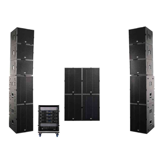
Page 12: Cobra System Amp Racks
The two illustrations show the internal cabling of the COBRA SYSTEM RACK from the rear. The control of the active 2-way COBRA and active 4-way COBRA-4 SYSTEMS is effected by their respective system racks (CSR-12 in the case of the COBRA SYSTEM and CSR-4 in the case of the COBRA-4 SYSTEM) which come pre-wired and factory-programmed. -
Page 13: Flying Accessories
13. FLYING ACCESSORIES The COBRA SYSTEM components COBRA-SUB, COBRA-TOP, COBRA-4-TOP and COBRA-4-FAR are supplied as standard with 4 vertical integrated ANCRA flying rails (2 x left and 2 x right) and are therefore ‘flight-ready’ when they leave the factory. Each flown ‘row’ is fastened to the truss with 4 x 2” truss clamps (TC-04 # 112 695) and the highest cabinet with 4 x CSST # 112 878 (Cobra System snap truss / 1 x double stud and 1 x hook). -
Page 14: Cobra System Country Specific Versions
112 875 112 875 112 875 112 875 112 875 * = COBRA : FIRMWARE 2.04 / COBRA-4 : Firmware 2.05 ** = CP 84 VERSION incl. 61 / 02 ( RS-485 ) COBRA-SYSTEM & COBRA-4-SYSTEM ACCESSORIES Part No. TYPE... -
Page 15: Technical Specifications
11. TECHNICAL SPECIFICATIONS SYSTEMS COBRA-SYSTEM COBRA-4-SYSTEM TYPE COBRA-SUB COBRA-TOP COBRA-PWH COBRA-4-TOP COBRA-4-FAR 112 868 112 869 112 895 112 898 112 897 ORDER No CABINET SUBWOOFER MID-HIGH CAB. SUBWOOFER MID-HIGH CAB. MID-HIGH CAB. CABINET TYPE VENTED PASSIVE 3-WAY HORN LOADED...
Need help?
Do you have a question about the COBRA-4 and is the answer not in the manual?
Questions and answers