Advertisement
Available languages
Available languages
Quick Links
VC6300 Volt Doctor
7/24/06
10:33 AM
Page 1
SPERRY
INSTRUMENTS
Volt Doctor
™
Voltage and Continuity Tester
• Read this owners manual thoroughly before use and save.
2150 Joshua's Path, Suite 302, Hauppauge, NY 11788
1-800-645-5398 • www.sperryinstruments.com
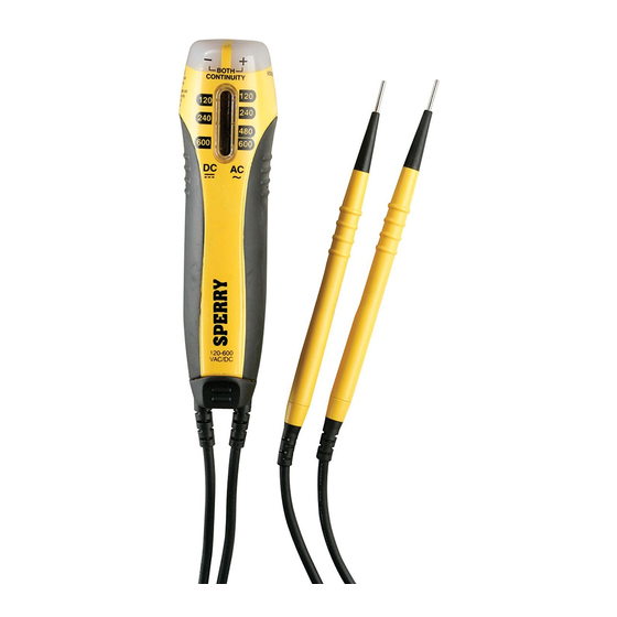
1.0 METER FUNCTIONS
1
4
2
3
5
2.0 READ FIRST: IMPORTANT SAFETY INFORMATION
Read this operators manual thoroughly before using this meter. This manual
is intended to provide basic information regarding this meter and to describe
common test procedures which can be made with this unit. Many types of appliance,
machinery and other electrical circuit measurements are not addressed in this manual and
should be handled by experienced service technicians.
Use extreme caution when using this meter. Improper use of this
!
WARNING
WARNING
meter can result in severe damage to property, severe personal injury
or death. Follow all instructions and suggestions in this operators manual as well
as observing normal electrical safety precautions. Do not use this meter if you are
unfamiliar with electrical circuits and proper test procedures.
SAFETY WARNINGS
This instrument has been designed, manufactured and tested according to IEC61010:
Safety requirements for Electronic Measuring apparatus, and delivered in the best
condition after passing inspection. This instruction manual contains warnings and safety
rules which must be observed by the user to ensure safe operation of the instrument and
retain it in safe condition. Therefore, read through these operating instructions before using
the instrument.
Keep the manual at hand to enable quick reference whenever necessary.
!
WARNING
WARNING
• The instrument is to be used only in its intended applications.
• Understand and follow all the safety instructions contained in the manual.
• It is essential that the above instructions are adhered to.
• Failure to follow the above instructions may cause injury, instrument
damage and/or damage to equipment under test.
is reserved for conditions and actions that can cause serious
!
DANGER
DANGER
or fatal injury.
is reserved for conditions and actions that can cause injury or
VC6300
instrument damage.
Never make measurement on a circuit in which voltage over
!
DANGER
DANGER
AC 600 V exists.
• Do not attempt to take measurements in the presence of flammable gasses. Otherwise,
the use of the instrument may cause sparking, which can lead to an explosion.
• This tester is designed for intermittent duty only (On 15 seconds, Off 240 seconds). It
should only take several seconds to note a voltage indication. If the reading is maintained
longer than 15 seconds, damage to the unit may occur.
Never attempt to use the instrument if its surface or your hand is wet.
!
WARNING
WARNING
• Do not exceed the maximum allowable input of any measuring range.
• Never open the battery cover during a measurement.
• The instrument is to be used only in its intended applications or conditions. Otherwise,
safety functions equipped with the instrument don't work, and instrument damage or
serious personal injury may be caused.
Never attempt to make measurements if any abnormal conditions, such as
!
WARNING
WARNING
broken case or exposed metal parts are found on the instrument.
• Do not install substitute parts or make any modification to the instrument. For repair or
1. DC Polarity Indicators
re-calibration, return the instrument to your local distributor from where it was purchased.
2. AC/DC Voltage Scale
• Disconnect all the cords and cables from the object under test before opening the battery
3. Probe Holders and
cover for battery replacement.
Storage
• Verify proper operation on a known source before use or taking action as a result of the
4. Continuity Indicator
indication of the instrument.
5. Battery Compartment
Use appropriate personal protective equipment such as insulating gloves,
insulating boots, and safety glasses.
• Do not expose the instrument to the direct sun, high temperature and humidity or dewfall.
• Using the meter in areas with high magnetic fields can result in inaccurate readings.
• Altitude 2000m or less. Appropriate operating temperature is within 32 °F – 104 °F
(0 °C – 40 °C).
• This instrument isn't dust and water proofed. Keep away from dust and water.
• When the instrument will not be in use for a long period, place it in storage after
removing the batteries.
• Cleaning: Use a cloth dipped in water or neutral detergent for cleaning the instrument.
Do not use abrasives or solvents otherwise instrument may get damaged, deformed
or discolored.
3.0 SPECIFICATIONS
DC Voltage: 120 - 600 Volts
AC Voltage: 120 - 600 Volts
AC Voltage Frequency: 50 - 60 Hz
Intermittent Duty Only! On 15 seconds, Off 240 seconds
Operation Environment: 32 °F – 104 °F (0 °C – 40 °C), 80% RH Max.
Altitude up to 2000 meters. Indoor use.
Storage Temperature: 14 °F – 140 °F (-10 °C – 60 °C)
Batteries: (2) 1.5 V button cells
CAT III 600V
4.0 OPERATION
This meter is designed with probe holders to
allow for maximum versatility and single hand
testing. Refer to the drawings in Fig. 1 for
common setups.
Automatic Operation
When using the test leads, the tester will
automatically activate when connected to
AC or DC voltage. The tester will
automatically select the proper function.
4.1 Testing Continuity
Touch the tip of the test leads to the points
where tests need to be made. If the
resistance is below 50 ohms, the continuity
light at the top will illuminate. Fig. 2
50% RH above 31 °C
Two
Single
Hand
Hand
Fig. 1
Beeper / Light
For
testing
probes
slide
down
from top
Fig. 2
Fig. 1
4.2 Measuring DC Voltage Levels
Measure the voltage by touching the test
lead tips to the circuit where the value of
voltage is needed. If the yellow test lead is
on the positive contact the +VDC light will
illuminate. If the yellow test lead is on the
negative contact the -VDC light will
illuminate. Fig. 3
Read the voltage level from the DC voltage
scale.
4.3 Measuring AC Voltage Levels
Measure the voltage by touching the test
lead tips to the circuit where the
value of voltage is needed. Both polarity
indicators will illuminate to indicate AC
Voltage. Fig. 4
Read the level from the AC voltage scale.
The polarity of the leads does not matter
for AC voltage measurements.
Fig. 3
5.0 CHANGING THE BATTERIES
Do not open tester case while using
the tester.
1) When the battery voltage drops below
proper operating range, the tester will
no longer function.
2) Slide rubber boot at the bottom of the
tester out of the way and remove the
screw to access the battery
compartment.
3) Slide the bottom out and replace with
(2) 1.5 Volt button cell batteries (LR44,
SR44, A76, G13, AG13, GP76A, 257,
D357, V13GA.
4) Replace battery door, screw and rubber
boot to original positions.
5) Test on known live circuit to verify proper
operation. Also test continuity function by
touching the two leads together.
(Refer to 1.0, Meter Functions)
Fig. 4
No Reaction
Yellow
Black
Advertisement

Related Manuals for Sperry instruments Volt Doctor VC6300


Summary of Contents for Sperry instruments Volt Doctor VC6300
- Page 1 VC6300 Volt Doctor 7/24/06 10:33 AM Page 1 is reserved for conditions and actions that can cause injury or SPERRY VC6300 Beeper / Light No Reaction instrument damage. testing Never make measurement on a circuit in which voltage over INSTRUMENTS DANGER DANGER probes...
- Page 2 VC6300 Volt Doctor 7/24/06 10:33 AM Page 2 SPERRY VC6300 se reserva para condiciones y acciones que pueden causar lesiones ¡PELIGRO! ¡PELIGRO! Para Señal sonora/Luz No hay reacción serias o fatales. probar se reserva para condiciones y acciones que pueden causar lesiones INSTRUMENTS PRECAUCION PRECAUCION !
Need help?
Do you have a question about the Volt Doctor VC6300 and is the answer not in the manual?
Questions and answers