Advertisement
Quick Links
Installation Instructions
Model OCM-16
Output Control Module
INTRODUCTION
OPERATION
P/N 315-033150-3
The SIEMENS Model OCM-16 Output Control Module
is a remotely located, general purpose output module. It
provides sixteen open collector outputs to drive LEDs,
incandescent lamps, or external relays. There is an
additional output for a local audible and two inputs for
momentary lamp test and local audible silence switches.
The OCM-16 is mounted in an enclosure that is re-
motely located from the Main Panel. Communication
between the OCM and the NIC-C is through the Control
Area Network (CAN) bus. Each OCM-16 has two 10
position rotary switches that are used to set the board
address on the CAN which is a sub-address of the
NIC-C. The 16 outputs of the OCM-16 are controlled by
messages received from the NIC-C over the CAN.
A CAN message can activate any or all of the 16 outputs
to drive LEDs, incandescent 24 Volt lamps or relays.
Whenever any of the outputs is activated, (LEDs, lamps
or relays ON) the local audible (if installed) will sound
until it is acknowledged by shorting position 19 and 20
on TB2. If the outputs are deactivated before the alarm
(local audible) is acknowledged, the alarm (local
audible) will cease to sound.
By shorting terminals 17 and 18, all LEDs or lamps will
turn on to confirm that they are working and automati-
cally will return to their normal state after a few sec-
onds. Both the lamp test and local audible silence
switch on multiple OCM-16s can be connected to a
single switch, one for each function. A single audible
can also be used with multiple OCM-16s.
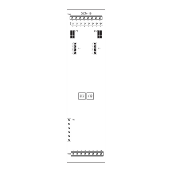
TB1
1
2
9
10
P2
1
2
3
4
S1
5
6
7
8
TB3
17
18
TB2
Figure 1
OCM-16 Output Control
Module
Siemens Building Technologies
OCM-16
3
4
5
6
7
8
11
12
13
14
15
16
P3
1
2
3
4
S2
5
6
7
8
19
20
21
22
23
24
Fire Safety
Advertisement

Subscribe to Our Youtube Channel
Related Manuals for Siemens OCM-16


Summary of Contents for Siemens OCM-16
- Page 1 OPERATION The OCM-16 is mounted in an enclosure that is re- motely located from the Main Panel. Communication between the OCM and the NIC-C is through the Control Area Network (CAN) bus.
- Page 2 INSTALLATION An OCM-16 may be installed in a REMBOX. When using REMBOX 2 or 4, mount the OCM-16 in one module space on a REMBOX2-MP , P/N 500-634211 or REMBOX4-MP , P/N 500-634212 using the four screws provided. (Refer to REMBOX2-MP/REMBOX4- MP Installation Instructions, P/N 315-034211.) Up to 4 OCM-16s will fit in a...
- Page 3 LAMP TEST* ACK ALARM* TO NEXT OCM-16 AUDIBLE DEVICE** – *NORMALLY OPEN MOMENTARY PUSHBUTTON (UL 864 LISTED) (UNSUPERVISED) **24VDC AUDIBLE 50mA MAX. (UL 864 LISTED) (UNSUPERVISED) Figure 2 OCM-16 Wiring Without An RNI Siemens Building Technologies P/N 315-033150-3 Fire Safety...
- Page 4 # CCL OCM-16 OCM-16 OCM-16 OCM-16 Figure 3 OCM-16 CAN Bus Connections With An RNI ELECTRICAL RATINGS i t c i t c For CE applications in Cerberus E100 systems refer to Installation Instruction A24205-A334-B844 (English) or A24205-A334-A844 (German). Siemens Building Technologies, Inc.
Need help?
Do you have a question about the OCM-16 and is the answer not in the manual?
Questions and answers