Table of Contents
Advertisement
1.1
Features
The Toshiba T4900CT is one of the lightest and most advanced portable computers available.
Utilizing advanced technology and high-speed components, the T4900CT offers excellent
color display legibility, battery operation, and IBM PC/AT compatibility. The T4900CT
system unit consists of the following features:
Microprocessor
The T4900CT uses an Intel Pentium
manual) that operates at 75 MHz, 3.3 Volts.
Math co-processor
The T4900CT has a math co-processor which is stored in the Pentium.
Cache memory
The T4900CT has a writeback type 16 KB cache memory which is stored in the
Pentium. The 16 KB cache consists of an 8 KB instruction cache and an 8 KB data
cache.
Disk storage
The T4900CT has an internal 2.5-inch 810 MB HDD. A 3.5-inch FDD supports 2 HD
(1.44 MB) floppy disks and 2DD (720 KB) floppy disks.
Memory
The T4900CT comes standard with 8 MB of CMOS type Dynamic Random Access
Memory (DRAM) 3.3 Volts. This includes 640 KB of conventional memory and
7,360 KB of extended memory which can be utilized as expanded memory compatible
with the Lotus/Intel/Microsoft Expanded Memory Specifications (LIM-EMS).
TFT color LCD
The T4900CT has a high-resolution 10.4-inch full-color, Thin Film Transistor (TFT)
color LCD that displays 640 x 480 pixels.
The T4900CT internal display controller supports VGA functions on the internal
display and SVGA functions on an external display.
Keyboard
An easy-to-use 82/84-key enhanced keyboard with full-size keys and standard spacing
is compatible with IBM standard software. The T4900CT's keybard supports soft-
ware that used a 101/102-key enhanced keyboard.
T4900CT
TM
Processor (referred to as Pentium in this
1-1
Advertisement
Table of Contents
Troubleshooting

Related Manuals for Toshiba T4900CT


Summary of Contents for Toshiba T4900CT
- Page 1 The T4900CT has a math co-processor which is stored in the Pentium. Cache memory The T4900CT has a writeback type 16 KB cache memory which is stored in the Pentium. The 16 KB cache consists of an 8 KB instruction cache and an 8 KB data cache.
- Page 2 The T4900CT’s Centronics compatible parallel interface port serves two purposes and can be used to connect a Centronics compatible printer. Mouse port The T4900CT has one 6-pin mouse port on the back that can be connected to an IBM PS/2 mouse. Keyboard port The T4900CT has one 6-pin keyboard port on the back that can be connected to an IBM PS/2 keyboard.
- Page 3 RGB port The T4900CT has one 15-pin RGB port on the back that can be connected to an external video display. Audio ports • Headphone, standard 3.5 mm diameter miniature stereo jack with speaker shut-off switch. • Use a headphone with an impedance of 16W.
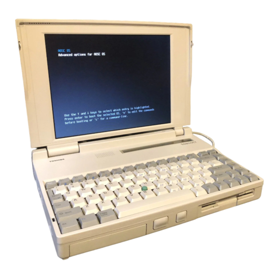
- Page 4 The T4900CT Personal Computer is shown in figure 1-1. The system configuration is shown in figure 1-2. Figure 1-1 T4900CT personal computer Figure 1-2 T4900CT system unit configuration T4900CT...
-
Page 5: System Unit Block Diagram
System Unit Block Diagram Figure 1-3 is a block diagram of T4900CT system unit. Figure 1-3 T4900CT system board block diagram T4900CT... - Page 6 The T4900CT system board shown in figure 1-3 is composed of the following major compo- nents: A pentium processor, which incorporates a math co-processor and16 KB cache memory. The following memory components: Standard RAM: 8 MB, 64-bit data width (70 ns)
- Page 7 • Bus Controller - 64 to/from 32-bit data path width convert - 32-bit local bus control • Address Latch Controller - Address convert - Address Latch • I/O Register - Register re-storing for resume - Special Register • Processing Speed Controller T4900CT...
- Page 8 IC Card Controller Gate Array This gate array has the following functions: • IC Card Controller - PCMCIA IC Card Controller - Toshiba Modem Card Controller • EEPROM (for security) Controller - KBC-Security-EEPROM Communication Controller • Others - KBC Communication Controller...
- Page 9 The T4900CT 3.5-inch Floppy Disk Drive (FDD) is a thin, high-performance reliable drive that supports 720-KB (formatted) 2DD and 1.44-MB (formatted) 2HD 3.5-inch floppy disks. The T4900CT FDD is shown in figure 1-4. The specifications for the FDD are described in table 1-1.
-
Page 10: Inch Hard Disk Drive
The Hard Disk Drive (HDD) is a random access non-volatile storage device. It has a non- removable 2.5-inch magnetic disk and mini-winchester type magnetic heads. T4900CT supports 810 MB HDD. The T4900CT HDD is shown in figure 1-5. Specifica- tions for the HDD are described in table 1-2. - Page 11 Keyboard The 82-(USA) or 84-(European) keyboard is mounted on the T4900CT’s system unit. The keyboard is connected to the keyboard controller on the system board through a 19-pin flat cable. The keyboard is shown in figure 1-6. See Appendix F for optional keyboard configurations.
-
Page 12: Tft Color Lcd
1.6.1 TFT Color LCD Module The T4900CT TFT color LCD supports 640 x 480 pixels with an internal display controller and 262144 colors for graphics and characters. This controller includes the functions of Video Graphics Array (VGA) and Super VGA (SVGA) for external display. - Page 13 1.6.2 Fluorescent Lamp (FL) Inverter Board The FL inverter board supplies high frequency current to light the LCD’s Fluorescent Lamp. The specifications for the T4900CT’s FL inverter are described in table 1-4. Table 1-4 FL inverter board specifications Item Specifications...
-
Page 14: Power Supply
Power Supply The power supply supplies five kinds of voltages to the T4900CT system board. The T4900CT power supply has one microprocessor and it operates at 500 KHz (power off) or 20 MHz (power on). It contains the following functions: Determines if the AC adapter or battery is connected to the computer. - Page 15 Batteries The T4900CT has three types of batteries: Main battery pack Backup battery Real Time Clock (RTC) battery These batteries’ specifications are described in table 1-6. Table 1-6 Batteries’ specifications Battery name Material Output voltage Capacity Main battery Nickel Metal Hydride...
- Page 16 If one of the following occurs, the battery quick-charge process stops. The battery becomes fully charged. The AC adapter or battery is removed. The battery or output voltage is abnormal. 1-16 T4900CT...
- Page 17 Table 1-9 shows the charging time and data preservation period of the RTC battery. Table 1-9 RTC battery charging/data preservation time Time Charging Time Power On 24 H Power Off 24 H Data preservation period (full charge) 1 month 1-17 T4900CT...
-
Page 18: Troubleshooting
Troubleshooting Chapter 2 describes how to determine if a Field Replaceable Unit (FRU) in the T4900CT is causing the computer to malfunction. The FRUs covered are: Power Supply Board System Board(s) Floppy Disk Drive Hard Disk Drive Keyboard Display Status Indicator Panel The Diagnostics Disk operations are described in Chapter 3 and detailed replacement proce- dures are given in Chapter 4. -
Page 19: Troubleshooting Flowchart
If the user has forgotten the password, contact your Toshiba representative for further action. Verify with the customer that Toshiba MS-DOS is installed on the hard disk. Non- Toshiba operating systems can cause the computer to malfunction. Make sure all optional equipment is disconnected from the computer. - Page 20 Figure 2-1 Troubleshooting flowchart (1/2) T4900CT...
- Page 21 If an error is detected on the floppy disk test, perform the floppy disk drive troubleshooting procedures in section 2.5. If an error is detected on the hard disk test, perform the hard disk drive troubleshooting procedures in section 2.6. T4900CT...
-
Page 22: Power Supply Troubleshooting
Power Supply Troubleshooting The T4900CT’s power supply controls many functions and components in the T4900CT. To determine if the power supply is functioning properly, start with Procedure 1 and continue with the other Procedures as instructed. The procedures described in this section are:... - Page 23 If the remaining battery time or percentage drops unexpectedly when you unplug the AC adapter, while the status indicator displays 100% battery charge, go to Procedure If the “P**” message appears on the battery capacity status area, perform Check 1. T4900CT...
- Page 24 Discharging current is not within the normal range while the power is off. VCC Output Status Meaning VCC Voltage is over the maximum allowed limit. VCC Voltage is below the minimum allowed limit. VCC Voltage error during the power on sequence. T4900CT...
- Page 25 Power Supply On/Off Sequence Status Meaning Sub-Battery Voltage is over the maximum allowed limit. Sub-Battery Charge Current is over the maximum allowed limit. Environment Status Meaning Frame temperature is not within the normal range. CPU temperature is not within the normal range. T4900CT...
- Page 26 PC temperature normalizes, go to Procedure 4. A thermistor near the CPU might be damaged. Check 7 When P10, P12, P20, P21, P22, P30, P31, P32, P33, P40, P41, P42, P50, P51, P60, or P61 is displayed, go to procedure 4. T4900CT...
- Page 27 Connect a new AC adapter. If the battery capacity does not change on the status indicator panel, go to Check 3. Check 3 Make sure the battery pack is installed in the computer correctly. If the battery pack is installed correctly, go to Procedure 3. 2-10 T4900CT...
- Page 28 The power supply may not charge the battery pack. Perform the following procedures: Install the battery pack in the T4900CT. Attach the AC adapter to the T4900CT, then turn on the power. (If you cannot turn on the power, go to Procedure 4.) Run the Diagnostic test, following the steps described in chapter 3, and select the system configurations.
- Page 29 The power supply board or system board(s) may be disconnected or damaged. Disassemble the T4900CT following the steps described in chapter 4, Replacement Procedures, and check the connection between the power supply and system board(s) and the status indicator panel.
- Page 30 Connect the AC adapter and charge the battery. The battery charge may increase quickly to 99%. Wait for the charge to reach 100%. Check 3 Repeat checks 1 and 2 two or three times until the battery capacity recovers. 2-13 T4900CT...
-
Page 31: System Board Troubleshooting
Procedure 1: Message Check Procedure 2: Printer Port LED Check on Boot mode Procedure 3: Printer Port LED Check on Resume Mode Procedure 4: Diagnostic Test Program Execution Check Procedure 5: Connection and Replacement Check 2-14 T4900CT... - Page 32 If an error message is shown on the display, perform Check 1. If there is no error message, go to Procedure 2. If the Toshiba MS-DOS is properly loaded, go to Procedure 3. Check 1 If one of the following error messages is displayed on the screen, press the F1 key as the message instructs.
- Page 33 PIC #1 ERROR (17) PIC #2 ERROR (18) KEYBOARD ERROR (19) KBC ERROR (20) HDC ERROR (21) HDD #0 ERROR (22) HDD #1 ERROR (23) NO FDD ERROR (24) FDD ERROR (25) TIMER INTERRUPT ERROR (26) RTC UPDATE ERROR 2-16 T4900CT...
- Page 34 Turn off the T4900CT’s power. Plug the printer port LED into the T4900CT’s PRT connector. Hold down the space bar and turn on the T4900CT’s power. Read the LED status from left to right as you are facing the back of the computer.
- Page 35 EXTENDED MEMORY ERROR ADDRESS = XXXXXXXXH READ DATA = XXXXXXXXH WRITE DATA = XXXXXXXXH EXTENDED MEMORY PARITY ERROR ADDRESS = XXXX0000H - XXXXFFFFH DMA page register test DMA PAGE REGISTER ERROR READ DATA = XXH WRITE DATA = XXH 2-18 T4900CT...
- Page 36 HDC #1 ERROR Hard RAM initialization FDD initialization NO FDD ERROR FDD ERROR Printer test RS-232-C test Timer initialization TIMER INTERRUPT ERROR RTC UPDATE ERROR NDP initialization Expansion I/O ROM Boot password 2 Boot setup Expansion system ROM 2-19 T4900CT...
- Page 37 If error code 4Ah is displayed, go to the Keyboard Troubleshooting procedures in section 2.7. Check 3 If error code 5Ah is displayed, go to the HDD Troubleshooting Procedures in section 2.6. Check 4 If error code 60h is displayed, go to the FDD Troubleshooting Procedures in section 2.5. 2-20 T4900CT...
- Page 38 NOTE: When you perform this check, set resume mode in SETUP. To use the printer port LED follow these steps: Turn on the T4900CT’s power, then set to resume mode. Turn off the T4900CT’s power Plug the printer port LED into the T4900CT’s PRT connector.
- Page 39 Execute the following tests from the Diagnostic Test Menu. Refer to Chapter 3, Tests and Diagnostics, for more information on how to perform these tests. System test Memory test Printer test ASYNC test Real Timer test NDP test Expansion test If an error is detected during these tests, go to Procedure 5. 2-22 T4900CT...
- Page 40 Procedure 5 Connection and Replacement Check The system board(s) may be disconnected or damaged. Disassemble the T4900CT following the steps described in chapter 4, Replacement Procedures, and check the connection between upper system board and lower system board, and other components. After checking the connection, perform the following checks.
- Page 41 Floppy Disk Drive Troubleshooting This section describes how to determine if the T4900CT’s internal 3.5-inch floppy disk drive is functioning properly. Perform the steps below starting with Procedure 1 and continuing with the other procedures as required. Procedure 1: FDD Head Cleaning Check...
- Page 42 Procedure 2 Diagnostic Test Program Execution Check The Floppy Disk Drive Diagnostic Test program is stored on the T4900CT Diagnostics Disk. After loading Toshiba MS-DOS, run the diagnostic program. Refer to Chapter 3, Tests and Diagnostics, for more information about the diagnostics test procedures.
- Page 43 The 3.5-inch Floppy Disk Drive is connected to the system unit by the FDD cable. This cable may be disconnected from the system board or may be damaged. Disassemble the T4900CT following the steps described in Chapter 4, Replacement Procedures, and perform the follow-...
-
Page 44: Hard Disk Drive Troubleshooting
Manual for more information about how to perform the BACKUP command. Procedure 1 Partition Check Insert the Toshiba MS-DOS system disk and turn on the computer. Then perform the follow- ing checks: Check 1 Type C: and press Enter. If you cannot change to drive C, go to Check 2. If you can change to drive C, go to Procedure 2. - Page 45 Procedure 2 Message Check When the T4900CT’s HDD does not function properly, some of the following error messages may appear on the display. Start with Check 1 below and perform the other checks as in- structed. Check 1 If any of the following messages appear, perform Check 2. If the following mes-...
- Page 46 The HDD is stored inside the HDD pack. The HDD pack connector is connected between the HDD and the lower system board. This connector may be disconnected from the lower system board or the HDD. Disassemble the T4900CT following the steps described in chapter 4, Replacement Procedures, and perform the following checks:...
- Page 47 Procedure 4 Format Check The T4900CT’s HDD is formatted using the low level format program and the MS-DOS FORMAT program. To format the HDD, start with Check 1 below and perform the other steps as required. Check 1 Using the Toshiba MS-DOS system disk, partition the hard disk using the FDISK command.
- Page 48 Procedure 5 Diagnostic Test Program Execution Check The HDD test program is stored in the T4900CT Diagnostics Disk. Perform all of the HDD tests in the Hard Disk Drive Test. Refer to Chapter 3, Tests and Diagnostics, for more infor- mation about the HDD test program.
- Page 49 The HDD peripheral component is composed of the HDD, HDD pack connector, lower system board, and upper system board. If any component is damaged, disassemble the T4900CT following the steps described in chapter 4, Replacement Procedures, and perform the following checks: Check 1 Replace the HDD with a new one.
-
Page 50: Keyboard Troubleshooting
Keyboard Troubleshooting To determine if the T4900CT’s keyboard is functioning properly, perform the following procedures. Start with Procedure 1 and continue with the other procedures as instructed. Procedure 1: Diagnostic Test Program Execution Check Procedure 2: Connector and Replacement Check... -
Page 51: Display Troubleshooting
Display Troubleshooting This section describes how to determine if the T4900CT’s display is functioning properly. Start with Procedure 1 and continue with the other procedures as instructed. Procedure 1: Hot Key Check Procedure 2: External CRT Check Procedure 3: Diagnostic Test Program Execution Check... - Page 52 Decreases the brightness of the LCD panel. Procedure 2 External CRT Check Connect the external CRT to the T4900CT’s external monitor port, then press Fn+F5. If the external CRT works correctly, the internal LCD display may be damaged. Go to Proce- dure 4.
- Page 53 Procedure 3 Diagnostic Test Program Execution Check The Display Test program is stored on the T4900CT Diagnostic Disk. This program checks the display controller on the system board. After loading Toshiba MS-DOS, run the Diagnos- tic Program. Refer to Chapter 3, Tests and Diagnostics, for details.
- Page 54 The upper system board may be damaged. Replace the upper system board with a new one and test the display again. If the problem still exists, perform Check 7. Check 7 Replace the lower system board with a new one. 2-37 T4900CT...
- Page 55 Status Indicator Panel Troubleshooting To determine if the T4900CT’s Status Indicator Panel is functioning properly, perform the following procedures. Start with Procedure 1 and continue with the other procedures as instructed. Procedure 1: Diagnostic Test Program Execution Check Procedure 2:...
-
Page 56: The Diagnostic Test
T4900CT’s hardware modules. The Diagnostics Test Program is stored on the T4900CT Diagnostic Disk. The Diagnostic Test consists of 8 programs that are grouped into the Service Program Module (DIAGNOSTIC MENU) and the Test Program Module (DIAGNOSTIC TEST MENU). -
Page 57: Executing The Diagnostic Test
Executing the Diagnostic Test Toshiba MS-DOS is required to run the T4900CT’s Diagnostics Test Program. To start the Diagnostics Test Program follow these steps: Turn on the computer, and allow the computer to boot. Insert the T4900CT Diagnostics Disk in the computer’s internal floppy disk drive. - Page 58 1, and press Enter. The following DIAGNOSTIC TEST MENU will appear: TOSHIBA Personal Computer TXXXX DIAGNOSTICS Version X.XX (C) Copyright TOSHIBA Corp. 19XX DIAGNOSTIC TEST MENU : 1 - SYSTEM TEST 2 - MEMORY TEST...
- Page 59 NOTE: The menu displayed by your T4900CT may be slightly different from the one shown above. Select the desired subtest number from the subtest menu and press Enter. The following message will appear: TEST LOOP : YES Selecting YES increases the pass counter by one, each time the test cycle ends, and restarts the test cycle.
- Page 60 320*200 Graphics display 640*200 Graphics display 640*350/480 Graphics display Display page “H” pattern display/Border color LCD/DAC pallet TFT color display Status indicator panel Sequential read Sequential read/write Random address/data Write specified address Read specified address PRINTER Ripple pattern Function Wrap around T4900CT...
- Page 61 Cross talk & peak shift Write/read/compare (CE) Write specified address Read specified address ECC circuit Sequential write W-R-C specified address REAL TIMER Real time Backup memory Real time carry NDP test EXPANSION PCMCIA Wrap around SOUND CODEC (REC/PLAY) SIN wave playback FM Synthesizer T4900CT...
-
Page 62: System Test
Sub-Test Menu. Table 3-2 Hardware bit status H/W status Reserved — — CPU clock speed 75MHz 75MHz Notch signal FDD type 1.6 MB 2 MB Reserved — — Reserved — — Reserved — — Internal FDD T4900CT... - Page 63 = V1.40 : OK V1.40 Reference data Current data Subtest 04 Main battery charge This subtest executes the quick charge to main battery. The following message is displayed. [Main battery charge] Subtest 05 Thermistor check This subtest checks the CPU temperature sensing thermistor. T4900CT...
-
Page 64: Memory Test
Protected mode This subtest writes constant data and address data to extended memory (maxi- mum address 100000h) then reads the new data and compares the result with the original data. The constant data is FFh, AAh, 55h, and 00h. T4900CT... - Page 65 After selecting subtest 05, the following message will appear: Extended memory size (1:4 MB,2:8 MB,3:16 MB,4:32 MB) ? Select the number that corresponds to the memory card installed in the T4900CT. Subtest 06 Cache memory To test the cache memory, a pass-through write-read comparison of ‘5A’ data is run repeatedly to test area (‘7000’:’Program’...
-
Page 66: Keyboard Test
To execute the Keyboard Test, select 3 from the DIAGNOSTIC TEST MENU, press Enter and follow the directions displayed on the screen. The Keyboard test contains two subtests that test the T4900CT’s keyboard actions. Move the highlight bar to the subtest you want to execute and press Enter. - Page 67 If this test does not detect an error, it returns to the subtest menu. If this test detects an error, the following message appears: KBC - MOUSE INTERFACE ERROR [[ HALT OPERATION ]] 1: Test end 2: Continue 3: Retry 3-12 T4900CT...
- Page 68 IPS switch is pressed, the <BUTTON> display alternates black and white and appears on the right side of the display. If two IPS switches are pressed, it returns to the subtest menu. << PRESS BUTTON1 + BUTTON2 THEN END >> 3-13 T4900CT...
-
Page 69: Display Test
To execute the Display Test, select 4 from the DIAGNOSTIC TEST MENU, press Enter, and follow the directions displayed on the screen. The Display test contains ten subtests that test the T4900CT’s display in various modes. Move the highlight bar to the subtest you want to execute and press Enter. - Page 70 In this subtest, the character set (addressed 00h to FFh) is displayed in the 40*25 character mode as shown below. Press [Enter] KEY To exit this subtest and return to the DISPLAY TEST menu, press Ctrl + Break. 3-15 T4900CT...
- Page 71 4 and D. One example is shown below: 320*200 GRAPHICS DISPLAY COLOR SET X : [X] GREEN BROWN CYAN MAGENTA WHITE PRESS [ENTER] KEY Pressing Enter toggles between tests. To exit this subtest and return to the DISPLAY TEST menu, press Ctrl + Break. 3-16 T4900CT...
- Page 72 640*XXX GRAPHICS DISPLAY EVEN DOTS ODD DOTS ALL DOTS DRIVEN DRIVEN DRIVEN PRESS [Enter] KEY Pressing Enter changes the size of the displayed image. To exit this subtest and return to the DISPLAY TEST menu, press Ctrl + Break. 3-17 T4900CT...
- Page 73 HHHHHHHHHHHHHHHHHHHHHHHHHHHHHHHHHHHHHHHHHHHHHHHHHH Pressing Enter displays the following message: Setting the color CRT (1:yes/2:no) If an external CRT display is connected to the T4900CT, choose 1 to display the following message: [Border color test (7 times press [Enter] key)] Press Enter to execute the border color test. To exit this subtest and return to the DISPLAY TEST menu, press Ctrl + Break.
- Page 74 After selecting this subtest, the following message will appear and all icons will be on. [Status Indicator Panel Display] Status Indicator Panel ALL ON PRESS [Enter] KEY After pressing Enter, all icons will be off, press Enter again to exit this subtest. 3-19 T4900CT...
-
Page 75: Floppy Disk Test
Enter, and follow the directions displayed on the screen. The Floppy Disk test contains five subtests that test the T4900CT’s internal floppy disk drive. The following messages will appear after selecting the Floppy Disk Test from the DIAGNOSTIC TEST MENU. Answer each question with the appropriate response to execute the test. - Page 76 3 above. The data is then read and compared to the original data. Subtest 04 Write Specified Address This subtest writes specified data to a specified track, head, and address. Subtest 05 Read Specified Address This subtest reads data from a specified track, head, and address. 3-21 T4900CT...
-
Page 77: Printer Test
= XXXXh channel#3 = XXXXh Select the channel number (1-3) ? The printer I/O port address is specified by the XXXXh number. The T4900CT supports three printer channels. Select the printer channel number, and press Enter to execute the selected subtest. - Page 78 The printer wraparound con- nector (34M741986G01) wiring diagram is described in Appendix G. This subtest checks the output and bidirectional modes of the data control and status lines through the printer wraparound connector. 3-23 T4900CT...
-
Page 79: Async Test
To execute the Async Test, select 7 from the DIAGNOSTIC TEST MENU, press Enter, and follow the directions displayed on the screen. The async test contains four subtests that test the T4900CT’s asynchronous communication functions. Move the highlight bar to the subtest you want to execute and press Enter. - Page 80 This subtest is used with subtest 03 described above. This subtest receives the data from the send side, then sends the received data. Subtest 04 Interrupt Test This subtest checks the Interrupt Request Level of IRQ 4, 3, and 5 from the send side. 3-25 T4900CT...
-
Page 81: Hard Disk Test
CAUTION: The contents of the hard disk will be erased when subtest 02, 03, 04, 05, 06, 08, 09, or 10 is executed. Before running the test, transfer the contents of the hard disk to a floppy disk(s). This can be done with the Toshiba MS-DOS BACKUP com- mand. - Page 82 • Forward sequential • Reverse sequential • Random Subtest 03 Random Address/Data This subtest writes random data to random addresses on the HDD cylinder, head, and sector. This data is then read and compared to the original data. 3-27 T4900CT...
- Page 83 This subtest writes specified 2-byte data to all of the cylinders on the HDD. Subtest 10 W-R-C specified address This subtest writes data to a specified cylinder and head on the HDD, then reads the data and compares it to the original data. 3-28 T4900CT...
-
Page 84: Real Timer Test
To execute the Real Timer Test, select 9 from the DIAGNOSTIC TEST MENU, press Enter, and follow the directions on the screen. The real timer test contains three subtests that test the T4900CT’s real timer functions. Move the highlight bar to the subtest you want to execute and press Enter. - Page 85 This subtest checks the real time clock increments, making sure the date and time are displayed in the following format: Current date 12-31-1992 Current time 23:59:58 Pressing Enter displays the following: Current date 1 01-01-1993 Current time 00:00:00 PRESS [Enter] KEY TO EXIT TEST Press Ctrl + Break to exit. 3-30 T4900CT...
-
Page 86: Ndp Test
3.13 NDP Test To execute the NDP test, select 10 from the DIAGNOSTIC TEST MENU, press Enter, and follow the directions on the screen. The NDP test contains one subtest that tests the T4900CT’s NDP functions. Subtest 01 NDP test... -
Page 87: Expansion Test
To execute the expansion test, select 11 from the DIAGNOSTIC TEST MENU, press Enter, and follow the directions on the screen. The expansion test contains one subtest that tests the T4900CT’s expansion port functions. The following message will appear after selecting the expansion test from the DIAGNOSTIC TEST MENU. -
Page 88: Sound Test
3.15 Sound Test To execute the expansion test, select 12 from the DIAGNOSTIC TEST MENU, press Enter, and follow the directions on the screen. The sound test contains three subtests that test the T4900CT’s sound functions. Subtest 01 CODEC (REC/PLAY) Test the functions of the Codec (AD1848) A/D, D/A converter. - Page 89 Record Not Found Media Removed DMA Overrun Error DMA Boundary Error CRC Error FDC Error Seek Error FDD Not Drive Error Time Out Error Write Buffer Error PRINTER Time Out Fault Select Line Out Of Paper Power Off Busy Line 3-34 T4900CT...
- Page 90 Control Word Error Status Word Error Bus Error Addition Error Multiplay Error PCMCIA Address Line Error REG# Line Error CE#1 Line Error CE#2 Line Error DATA Line Error WAIT Line Error BSY# Line Error BVD1 Line Error No PCMCIA 3-35 T4900CT...
-
Page 91: Hard Disk Test Detail Status
“1” --- Drive is ready for data transfer. CORR “0” --- Other (Corrected data) “1” --- Correctable data error is corrected. “0” --- Other (Index) “1” --- Index is sensed. “0” --- Other (Error) “1” --- The previous command was terminated with some error. 3-36 T4900CT... - Page 92 “1” Illegal command error or a drive status error occurred. TK00 “0” The hard disk found track 0 during a recalibrate command. (Track 0) “1” The hard disk could not find track 0 during a recalibrate command. —— Not used. 3-37 T4900CT...
-
Page 93: Hard Disk Format
CAUTION: The contents of the hard disk will be erased when this program is executed. Before executing the function, transfer the contents of the hard disk onto a floppy disk(s). This can be done with the Toshiba MS-DOS BACKUP command. See the Toshiba MS-DOS manual for details. - Page 94 CAUTION: After the HDD has been formatted, execute the Toshiba MS-DOS FDISK command, to partition the HDD. Next, execute the Toshiba MS-DOS FORMAT com- mand. Refer to the Toshiba MS-DOS manual for more information about using these commands. Selecting test 2 in the DIAGNOSTIC MENU and pressing Enter, displays the following messages: DIAGNOSTICS - HARD DISK FORMAT : VX.XX...
- Page 95 (f) below. Track verification A check is made of all tracks and if an ECC error, ECC-correctable-data error, or record-not-found error is detected at a track, that track is automati- cally formatted as a bad track. 3-40 T4900CT...
- Page 96 Drive number select (1:#1, 2:#2) ? Bad tracks will be displayed in the format shown be- low. [[cylinder, head = 0123 03]] Press Enter to return to the Hard Disk Format menu. 3-41 T4900CT...
-
Page 97: Head Cleaning
Remove the Diagnostics Disk from the FDD. Then insert the cleaning disk and press Enter. When the cleaning start message appears, the FDD head cleaning has begun. The display automatically returns to the DIAGNOSTIC MENU when the program is completed. 3-42 T4900CT... -
Page 98: Log Utilities
001 FDD 01 0000 180 00001 00 00 FDD - TIME OUT ERROR Address Error status Pass count HDC status Subtest number Read data Test name Write data Error count Error status name [[1:Next,2:Prev,3:Exit,4:Clear,5:Print,6:FD Log Read,7:FD Log Write]] 3-43 T4900CT... - Page 99 The 7 key writes the log information to a floppy disk. In the case of “error retry OK,” a capital “R” will be placed at the beginning of the error status. However, it is not added to the error count. 3-44 T4900CT...
-
Page 100: Running Test
Printer wrap around test (Y/N) ? Selecting Y (yes) executes the printer wraparound test. A printer wraparound connector must be connected to the PRT port on the back of the T4900CT to properly execute this test. Select Y or N and press Enter. The following message will appear: Serial #A wrap around test (Y/N) ? Selecting Y (yes) executes the ASYNC wraparound test. - Page 101 Select Yes or No and press Enter. The following message will appear : Mount the work disk(s) on the drive(s), then press [Enter] key. [Warning : The contents of the disk(s) will be destroyed] This program is executed continuously. To terminate the program, press Ctrl + Break. 3-46 T4900CT...
-
Page 102: Floppy Disk Drive Utilities
FORMAT NOTE: This program is only for testing a floppy disk drive. The option is different from the Toshiba MS-DOS FORMAT command. This program can format a 3.5-inch floppy disk in the following formats: 2D: Double-sided, double-density, 48/67.5 TPI, MFM mode, 512 bytes, 9 sectors/track. - Page 103 When COPY is selected, the following message appears: FLOPPY DISK FORMAT & COPY : VX.XX Type select (0:2DD-2DD,1:2D-2D,2:2D-2HD,3:2HD-2HD) ? Select a media/drive type number to display a message similar to the one below: Insert source disk into drive A: Press any key when ready. 3-48 T4900CT...
- Page 104 —— Max. address —— [Track ] = 0079 [ Head ] = 01 [Sector] = 09 Track number ?? Set the track number you want to dump. Then, the system will access the disk and dump a list. 3-49 T4900CT...
-
Page 105: System Configuration
3.23 System Configuration 3.23.1 Function Description The System Configuration program contains the following configuration information for the T4900CT: BIOS ROM version Boot ROM version The number of math co-processors KBC version Base memory size The number of floppy disk drives... - Page 106 Battery Save Mode Battery Display Manual Set of Battery Level POWER ON PASSWORD OTHERS Power-up Mode CPU Cache Speaker Volume Panel Power On/Off Alarm Power On Pointing Devices Hotkey Boot Priority Sound I/O Address Ext. Keyboard “Fn” key equivalent 3-51 T4900CT...
-
Page 107: Accessing The Setup Program
3.24.2 Accessing the SETUP Program Select 0 from the DIAGNOSTICS MENU and press Enter to display the following: T4900CT SETUP BIOS Version = *.** MEMORY BATTERY Battery Save Mode = Economy Power Total = 8192KB Battery Display = Time Base... - Page 108 Extended This field displays the amount of extended memory the computer has avail- able. Shadow BIOS ROM The SETUP program displays 192 KB of RAM, which is reserved for the Shadow BIOS ROM. 3-53 T4900CT...
- Page 109 This option selects interlace or non-interlace mode for an external monitor with a resolution of 1,024 x 768 pixels. Interlace Every other line is scanned during each total vertical (full) screen refresh. (Default) Non-Interlace Each line is scanned during each total vertical (full) screen refresh. 3-54 T4900CT...
- Page 110 The system starts up by using both the internal and external displays. Text Mode Stretch This option sets the text mode stretch on the LCD. Enabled Text mode stretch is enabled. (Default) Disabled Text mode stretch is disabled. 3-55 T4900CT...
- Page 111 This option sets the communication mode for the PRT port to either output-only or bi-directional. For most printers, the port should be set to output. With some other parallel devices, the setting should be set to bi- directional. Output Activates uni-directional operation. (Default) Bi-directional Activates bi-directional operation. 3-56 T4900CT...
- Page 112 Economy Power The following shows economy power settings. BATTERY SAVE OPTIONS Processing Speed High CPU Sleep Mode Enabled Display Auto Off 03 Min. HDD Auto Off 03 Min. System Auto Off Disabled (only Resume mode) Max. LCD Brightness 3-57 T4900CT...
- Page 113 This option is used to set the CPU operating speed to High or Low. Processing speed CPU speed High 75MHz 37.5 MHz (Equivalent) CPU Sleep Mode This option is used to enable and disable the CPU sleep function. Enabled Enables sleep mode. Disabled Disables sleep mode. 3-58 T4900CT...
- Page 114 10, 20, 30, 40, 50, or 60 minutes. Max. LCD Brightness This option selects the LCD’s maximum brightness level, a high level or a low level. High LCD’s maximum brightness level is set to high. LCD’s maximum brightness level is set to low. 3-59 T4900CT...
- Page 115 Battery Display This option selects how the status indicator panel indicates the remaining battery capacity when the T4900CT is not connected to the AC adapter. The options are: Time The status indicator panel indicates how much battery power is left. The status indicator panel indicates an estimated time for which the T4900CT can operate with the remaining battery power.
- Page 116 Others Whether or not you need to configure the T4900CT with these options depends primarily on the kind of software or peripherals to be used. Power-up Mode This option enables and disables the AutoResume feature. You can also set this option using the Hot Key. Disabling AutoResume enables boot mode.
- Page 117 When the system is set to Boot mode, this option is automatically disabled. Enabled Enables the system automatic power off when the display panel is closed. Disabled Disables the system automatic power off when the display panel is closed. (Default) 3-62 T4900CT...
- Page 118 Alarm power on feature is disabled. hh:mm:ss Alarm power on feature is enabled. If you enable this option, the T4900CT will be powered on and boot up, or resume automatically at the time you set here. Pointing Devices This option enables selection of the pointing device.
- Page 119 Left Alt + Left Shift functions as the Fn key. Right Alt + Right Shift Right Alt + Right Shift functions as the Fn key. Left Alt + Caps Lock Left Alt + Caps Lock functions as the Fn key. 3-64 T4900CT...
- Page 120 FRUs which need to be removed in order to remove others. Always start by removing the battery pack, then follow the lines on the chart to determine which FRU you must remove next in order to repair the one you think is causing the T4900CT to operate improperly.
- Page 121 Warning: Wait at least five minutes after turning off the power before you begin disas- sembly. The T4900CT’s processor operates at high temperature and there is a danger of incurring burns if you touch the chassis while it is hot.
- Page 122 When assembling the T4900CT make sure you use the correct screws to secure the various pieces in place. Screw sizes are listed in the corresponding figures. The T4900CT contains many sharp edges and corners, so be careful not to injure yourself.
- Page 123 Toshiba. Installation of the wrong battery can cause the battery to explode. After installing an FRU in the T4900CT, confirm that the FRU and the T4900CT are func- tioning properly.
-
Page 124: The Battery Pack
The Battery Pack Removing the Battery Pack To remove the T4900CT battery pack, follow the steps below and refer to figure 4-1. Turn off the power to the T4900CT. Disconnect the AC adapter, power cord, and all external cables connected to the T4900CT. - Page 125 Optional Memory Card Removing an Optional Memory Card To remove an optional memory card from the T4900CT, follow the steps below and refer to figures 4-2 and 4-3. Turn off the power to the T4900CT. Disconnect the AC adapter, power cord, and all external cables connected to the T4900CT.
- Page 126 Installing an Optional Memory Card To install an optional memory card in the T4900CT, follow the steps below and refer to figures 4-2 and 4-3. The top of the optional memory card is marked with the word “insert” and an arrow pointing toward the connecting edge.
- Page 127 Removing an Optional PCMCIA Card The T4900CT has two PCMCIA slots: one for a card up to 5.0 mm (slot 2) and one for a card up to 16 mm (slot 1). To remove optional PCMCIA cards, follow the steps below and refer to figures 4-4 through 4-6: Turn off the power to the T4900CT.
- Page 128 Figure 4-6 Removing the card from the PCMCIA card slot 1 Installing an Optional PCMCIA Card To install the optional PCMCIA cards in the T4900CT, follow the steps below and refer to figures 4-4 through 4-6: To install a PCMCIA card into PCMCIA card slot 2, carefully insert the card, making sure the card is right side up and the contact surface is inserted first (figure 4-4).
- Page 129 Hard Disk Drive Removing the Hard Disk Drive To remove the T4900CT’s hard disk drive, follow the steps below and refer to figures 4-7 through 4-10. Turn off the power to the T4900CT. Disconnect the AC adapter, power cord, and all external cables connected to the T4900CT.
- Page 130 Figure 4-8 Removing the HDD pack Remove the VOID seal, and remove four M3x4 flat-head screws securing the case to the HDD pack. Open the case and lift out the HDD pack (figure 4-9). Figure 4-9 Removing the cover 4-11 T4900CT...
- Page 131 Figure 4-10 Removing the HDD Installing the HDD To install the T4900CT’s HDD, follow the steps below and refer to figures 4-7 through 4-10. Connect the FPC connector to the HDD and seat the HDD into the bottom half of the case (figures 4-9 and 4-10).
-
Page 132: Top Cover
Top Cover Removing the Top Cover To remove the T4900CT’s top cover, follow the steps below and refer to figures 4-11 to 4- Turn off the power to the T4900CT. Disconnect the AC adapter, power cord, and all external cables connected to the T4900CT. - Page 133 Turn the T4900CT right side up so that the back of the computer faces you. Remove four M2.5x6 silver screws securing the top cover at the back of the T4900CT. If you are going to disassemble the middle frame, also remove two M2.5x6 screws securing the bottom cover (figure 4-12).
- Page 134 Installing the Top Cover To install the T4900CT’s top cover, follow the steps below and refer to figures 4-11 through 4-13. Place the top cover on the T4900CT. Begin at the back and snap the top cover into place, continuing along the sides and finally the front until all 14 latches are snapped (figure 4-13).
- Page 135 Keyboard Removing the Keyboard To remove the T4900CT’s keyboard, follow the steps below and refer to figure 4-14. Turn off the power to the T4900CT. Disconnect the AC adapter, power cord, and all external cables connected to the T4900CT. Remove the battery pack, optional memory card, optional PCMCIA card, HDD pack, and top cover as described in sections 4.2 through 4.6.
- Page 136 Connect the keyboard cable to the pressure plate connector (PJ9) on the upper system board. Seat the keyboard in the T4900CT. Note that a fold is built into the keyboard cable. Do not try to bend the cable at any other point when you install the key- board.
- Page 137 Status Indicator Panel Removing the Status Indicator Panel To remove the T4900CT’s status indicator panel, follow the steps below and refer to figure 4- Turn off the power to the T4900CT. Disconnect the AC adapter, power cord, and all external cables connected to the T4900CT.
- Page 138 Installing the Status Indicator Panel To install the T4900CT’s status indicator panel, follow the steps below and refer to figure 4- Connect the status indicator panel cable to the pressure plate connector (PJ8) on the upper system board. Set the status indicator panel in the upper system board cover, making sure it is seated securely in its brackets.
- Page 139 Backup Battery and Microphone Removing the Backup Battery and Microphone To remove the T4900CT’s backup battery and microphone, follow the steps below and refer to figure 4-17. Turn off the power to the T4900CT. Disconnect the AC adapter, power cord, and all external cables connected to the T4900CT.
- Page 140 Toshiba. Installation of the wrong battery can cause the battery to explode. To install the T4900CT’s backup battery and microphone, follow the steps below and refer to figures 4-18 through 4-20. Fit the two notches on the microphone onto two prongs on the computer (figure 4-18).
- Page 141 Lay the backup battery and cables in place on the computer and secure them with tape (figure 4-20). Install the top cover, HDD pack, optional PCMCIA card, optional memory card, and battery pack as described in sections 4.6 back through 4.2. 4-22 T4900CT...
-
Page 142: Display Assembly
4.10 Display Assembly Removing the Display Assembly To remove the T4900CT’s display assembly, follow the steps below and refer to figures 4-21 through 4-24. Turn off the power to the T4900CT. Disconnect the AC adapter, power cord, and all external cables connected to the T4900CT. - Page 143 Figure 4-22 Removing the display, FL, and ground cables Turn the computer around and remove the two M2.5x6 silver screws on the back of the computer which secure the display assembly (figure 4-23). Figure 4-23 Removing the screws (back of computer) securing the display assembly 4-24 T4900CT...
- Page 144 (figure 4-24). Figure 4-24 Removing the display assembly If you are going to disassemble the display assembly, go to section 4.16. 4-25 T4900CT...
- Page 145 Installing the Display Assembly To install the T4900CT’s display assembly, follow the steps below and refer to figures 4-21 through 4-24. Place the display assembly on the computer, making sure the brackets on the display fit in front of the corresponding brackets on the computer.
- Page 146 4.11 Speaker, Upper System Board, and Power Supply Board Removing the Speaker, Upper System Board, and Power Supply Board To remove the T4900CT’s upper system board and power supply board, follow the steps below and refer to figures 4-25 through 4-27.
- Page 147 DC IN jack (figure 26). Figure 4-26 Removing the upper system board Turn the upper system board upside down, and remove the power supply board (figure 4-27). Figure 4-27 Removing the power supply board 4-28 T4900CT...
- Page 148 Installing the Speaker, Upper System Board, and Power Supply Board To install the T4900CT’s speaker, upper system board, and power supply board, follow the steps below and refer to figures 4-25 through 4-27. Connect the power supply board to the upper system board (figure 4-27).
- Page 149 4.12 Base Assembly and Power/Reset Board Removing the Base Assembly To remove the T4900CT’s base assembly, follow the steps below and refer to figures 4-28 through 4-31. Turn off the power to the T4900CT. Disconnect the AC adapter, power cord, and all external cables connected to the T4900CT.
- Page 150 Figure 4-29 Removing the base assembly Disconnect the power/reset cable from the power/reset board (figure 4-30). Figure 4-30 Removing the power/reset cable 4-31 T4900CT...
- Page 151 Installing the Base Assembly To install the T4900CT’s base assembly and power/reset board, follow the steps below and refer to figures 4-26 and 4-28 through 4-31. Connect the power/reset cable to the power/reset board (figure 4-30). Seat the power/reset board inside its brackets on the bottom cover, then fold the power/reset cable down into the slot in front of the system board.
-
Page 152: Floppy Disk Drive
4.13 Floppy Disk Drive Removing the Floppy Disk Drive To remove the T4900CT’s floppy disk drive, follow the steps below and refer to figures 4-32 and 4-33. Turn off the power to the T4900CT. Disconnect the AC adapter, power cord, and all external cables connected to the T4900CT. - Page 153 4-33, which secure the FDD and pull the FDD out of the base assembly. Caution: Be careful not to touch the rectangle on the FDD. This area is just above the read/write head and is very sensitive to damage. Figure 4-33 Removing the FDD 4-34 T4900CT...
- Page 154 Installing the Floppy Disk Drive To install the T4900CT’s floppy disk drive, follow the steps below and refer to figures 4-32 and 4-33. Place the FDD in the base assembly and, holding the FDD with your hand so it doesn’t fall out, turn the base assembly over.
-
Page 155: Rtc Battery
4.14 RTC Battery Removing the RTC Battery To remove the T4900CT’s speaker and RTC battery follow the steps below and refer to figures 4-34 and 4-35. Turn off the power to the T4900CT and disconnect the AC adapter, power cord, and all external cables connected to the T4900CT. - Page 156 Disconnect the RTC battery cable from the PCMCIA slot 2 connector board (figure 4-35). Figure 4-35 Disconnecting the RTC battery 4-37 T4900CT...
- Page 157 Toshiba. Installation of the wrong battery can cause the battery to explode. To install the T4900CT’s RTC battery follow the steps below and refer to figures 4-34 and 4- Connect the RTC battery cable to the PCMCIA slot 2 connector board (figure 4-35).
- Page 158 4.15 Lower System Board Removing the Lower System Board To remove the T4900CT’s lower system board, follow the steps below and refer to figures 4- 36 through 4-38. Turn off the power to the T4900CT and disconnect the AC adapter, power cord, and all external cables connected to the T4900CT.
- Page 159 (figure 4-37). Figure 4-37 Removing the lower system board Turn the lower system board over and disconnect the sound system board from the lower system board (figure 4-38). Figure 4-38 Removing the sound system board 4-40 T4900CT...
- Page 160 Installing the Lower System Board To install the T4900CT’s lower system board, follow the steps below and refer to figures 4-36 through 4-38. Connect the sound system board to lower system board, then place the lower system board on the base assembly frame (figure 4-38).
-
Page 161: Display Mask
4.16 Display Mask Removing the Display Mask To remove the T4900CT’s display mask, follow the steps below and refer to figure 4-39. Turn off the power to the T4900CT and disconnect the AC adapter, power cord, and all external cables connected to the T4900CT. - Page 162 Installing the Display Mask To install the T4900CT's display mask, follow the steps below and refer to figure 4-39. Set the display mask in place and secure the latches beginning with the three latches in the display supports (two in the larger support and one in the small support.
- Page 163 4.17 T4900CT FL Inverter Board Removing the FL Inverter Board To remove the T4900CT’s FL inverter board, follow the steps below and refer to figures 4-40 and 4-41. Turn off the power to the computer. Disconnect the AC adapter and all external cables connected to the computer.
- Page 164 Installing the FL Inverter Board To install the T4900CT’s FL inverter board, follow the steps below and refer to figures 4-40 and 4-41. Connect the FL inverter cable to CN1 and the FL cable to CN2 on the FL inverter board (figure 4-41).
- Page 165 4.18 T4900CT TFT Color LCD Module Removing the TFT Color LCD Module To remove the T4900CT’s LCD module, follow these steps and refer to figure 4-42. Turn off the power to the T4900CT. Disconnect the AC adapter, power cord, and all external cables connected to the T4900CT.
- Page 166 Installing the TFT Color LCD Module To install the T4900CT’s TFT color LCD module, follow the steps below and refer to figure 4-42. Connect the display cables to CN11 and CN12 on the LCD module. Align the LCD module and then secure it with four M2.5x6 screws.
- Page 167 LCD panel. Any contamination can affect the perfor- mance of the unit. To remove the T4900CT’s FL unit, follow the steps below and refer to figure 4-43. Turn off the power to the computer. Disconnect the AC adapter and all external cables connected to the computer.
- Page 168 4.20 FL Inverter Cable, Display Cable Removing the Display Cable To remove the T4900CT’s display cable, follow the steps below and refer to figure 4-44. Turn off the power to the T4900CT. Disconnect the AC adapter, power cord, and all external cables connected to the T4900CT.
- Page 169 Installing the Display Cable To install the T4900CT’s display cable, follow the steps below and refer to figure 4-44. Fit the display cable to the display cover and secure the display hinge with two M2.5x6 screws. Secure the ground cable to the display cover with one M2.5x6 screw.
- Page 170 4.21 Panel Close Switch Removing the Panel Close Switch To remove the T4900CT’s panel close switch, follow the steps below and refer to figure 4-45. Turn off the power to the T4900CT. Disconnect the AC adapter, power cord, and all external cables connected to the T4900CT.
-
Page 171: Appendix A Handling The Lcd Module
LCD cover before securing the module with screws. Do not force the module into place, because stress can affect its performance. Also, the panel’s polarized surface is easily scarred, so be careful when handing it. T4900CT... - Page 172 Be sure to quickly wipe off any liquid. Glass is used in the panel, so be careful not to drop it or let it strike a hard object, which could cause breakage or cracks. T4900CT...
- Page 173 Do not expose the module to direct sunlight or strong ultraviolet rays for long periods. Do not store the module at temperatures below specifications. Cold can cause the liquid crystals to freeze, lose their elasticity or otherwise suffer damage. T4900CT...
- Page 174 Do not disassemble the LCD module. Disassembly can cause malfunctions. If you transport the module, do not use packing material that contains epoxy resin (amine) or silicon glue (alcohol or oxime). These materials can release gas that can damage the panel's polarization. T4900CT...
- Page 175 Appendix B Board Layout Upper System Board Figure B-1 Upper system board (front) T4900CT...
- Page 176 Figure B-2 Upper system board (back) T4900CT...
- Page 177 Name IC5 to IC8 System Memory SCPCNT-GA SISCNT-GA IC21 SLCDC-GA IC23 Keyboard Controller IC19 32.768KHz Crystal IC29,30 KB Scan Return Buffer IC27,28 KB Scan Output Buffer IC25 IPS Controller PS Connector PJ11 Joint Connector 2 PJ10 Joint Connector 1 T4900CT...
- Page 178 Lower System Board Figure B-3 Lower system board (front) T4900CT...
- Page 179 Figure B-4 Lower system board (back) T4900CT...
- Page 180 PJ302 Joint Connector 2 Table B-4 Lower ICs and connectors on the system board (back) Mark Number Name IC303 SI : T6W23 IC314 PCMCIA Card Controller GA IC300 BIOS BOM PJ305 HDD Connector PJ309,310 PCMCIA Slot 2 Joint Connector T4900CT...
-
Page 181: Appendix C Pin Assignments
ERAS1;001 ERAS0;001 ECAS2;001 ECAS0;001 — ECAS1;001 ECAS3;011 — ERAS1;001 ERAS0;001 EMWE2;001 — — ECAS0;001 ECAS1;001 — ECAS2;001 D08;100 ECAS3;001 — — D09;100 D24;100 — D25;100 D10;100 D26;100 D11;100 D27;100 D12;100 D28;100 D13;100 D29;100 D14;100 D30;100 D15;100 D31;100 — — T4900CT... - Page 182 P21;104 P4;104 P1;104 — — PNEL0;100 P5;104 P10;104 — P3;104 P14;104 P11;104 — — P8;104 SHFCLK;104 P15;104 P22;104 ENDATA;104 — — P6;104 P0;104 P19;104 FP;104 P12;104 P7;104 — — P9;104 LP;104 P20;104 — P13;104 P23;104 — — P18;104 — T4900CT...
- Page 183 SPKVOL;100 PSAD3;100 BRTCNT;100 PSAD2;100 PSRST;000 PSAD1;100 DSKDC RSTSW;000 PSAD0;100 DSKDC PWRSW;000 DSKDC PNLOF;000 DSKDC PSRWO;000 DSKDC PSTMG;000 DSKDC ADPCNT;100 DSPV PSUPDT;100 DSPV SUSSTA;001 P12V PSREQ;000 RCLR;100 LOBAT;000 CPUGND PCLR;000 CPUTMP BEEP;000 PSAD7;100 CPCNF;100 PSAD6;100 ENVCC;010 PSAD5;100 ENB3V;000 PSAD4;100 SUBBAT T4900CT...
- Page 184 — — PJ6 Panel Close Switch Connector (2-Pin) Table C-6 Panel close switch connector pin assignments (2-pin) Signal Signal PNLOFF;000 — PJ7 Power/Reset Switch Connector (3-Pin) Table C-7 Power/Reset switch connector pin assignments (3-pin) Signal Signal RSTSW;010 PWRSW;010 — T4900CT...
- Page 185 LSEG01;110 PJ9 KB I/F Connector (25-Pin) Table C-9 KB I/F connector pin assignments (25-pin) Signal Signal KBOT00;010 KBOT06;010 KBRT6;110 KBOT08;010 KBRT0;110 KBOT02;010 KBRT2;110 KBOT07;010 KBRT3;110 KBOT09;010 KBRT1;110 KBOT10;010 KBRT7;110 IPSY;100 KBRT5;110 KBRT4;110 IPSX;100 KBOT01;010 IPSX;100 KBOT03;010 KBOT04;010 IPSX;100 KBOT05;010 T4900CT...
- Page 186 BLUE;100 ESMI1;000 HSYNC;100 LGREN;100 RED;100 DMAWR;000 SD00;100 IMCS16;000 SD15;100 DMARDY;100 SD01;100 ZEROWS;000 SD14;100 DMACLK;100 SD02;100 BALE;100 SD13;100 HLDACK;100 SD03;100 ROMCS;000 SD12;100 DMEN16;100 PCLR;000 HREQ;100 SD04;100 PCMRST;100 SD11;100 KBCS;000 SD05;100 MERD;000 SD10;100 TMOUT;100 SD06;100 MEWR;000 SA09;100 TMOUT2;100 SD07;100 TIMGT2;100 SD08;100 T4900CT...
- Page 187 MOSDT;100 RESET;000 KBOT07;000 DACK3;000 KBOT06;000 SPKDRV;000 DACK2;000 SPKVOL;100 KBOT05;000 EPNLOF;000 KBOT03;000 IOWR;000 KBOT04;000 IORD;000 KBOT01;000 IMICIN;100 KBOT02;000 KBOT00;000 SPKM;100 KEYPRS;100 KBTMG;100 AGNDIM MASTER;000 BEEP;000 KBRWO;000 DSKDC DACK4;000 SMER;000 IHMED;000 DSKDC DACK7;000 SMEW;000 REFRSH;000 DSKDC DACK6;000 CPCNF;100 SPKP;100 IRQ12;100 ADPCNT;100 T4900CT...
- Page 188 Table C-12 Microphone connector pin assignments (3-pin) Signal Signal IMICIN;100 N.C. — AGNDIM C.13 PJ13 Switch Board Connector (4-Pin) Table C-13 Switch board connector pin assignments (4-pin) Signal Signal C.14 PJ14 Speaker Connector (2-Pin) Table C-14 Speaker connector pin assignments (2-pin) Signal Signal SPKP;100 SPKM;100 T4900CT...
- Page 189 PJ304 FDD Connector (26-Pin) Table C-16 FDD connector pin assignments (26-pin) Signal Signal ISSEL;000 — — IDIRC;000 IRDAT;000 ILOWD;000 — IMON;000 IWPR;000 IHMED;000 — IRDY;000 ITR0;000 — — DSKCHG;000 IWEN;000 — — IDSL;000 IWDAT;000 — — IINDEX;000 ISTEP;000 — T4900CT...
- Page 190 — — SA00;100 — SA02;100 SD03;102 — SD12;102 — — HDDCS2;010 — HDDCS1;010 SD02;102 — SD13;102 HDDVCC — — DRVSL;000 — HDDVCC — SD01;102 HDDVCC — SD14;102 HDDVCC — — HDDVCC — — HDDIN;000 SD00;102 ATSEL;100 SD15;102 — C-10 T4900CT...
- Page 191 C.18 PJ306 Serial I/F Connector (9-Pin) Table C-18 Serial I/F connector pin assignments (9-pin) Signal Signal DCD1;101 DSR1;101 RD1;001 RTS1;101 SD1;001 CTS1;101 DTR1;101 RI1;101 — C-11 T4900CT...
- Page 192 — SD01;101 CPCNF;100 SD02;101 MDMSL;001 SD03;101 $14R7M;100 — MIRQ;001 SD04;101 SPKTON;001 SD05;101 — SD06;101 SA00;101 SD07;101 SA01;101 SMEW;001 SA02;101 SMER;001 SA03;101 — SA04;101 IOWR;001 SA05;101 IORD;001 SA06;101 TC;101 SA07;101 BALE;101 — RESET;101 SA08;101 DACK1;001 SA09;101 IRQ9;101 SA10;101 — C-12 T4900CT...
- Page 193 LA21;101 ACK;000 LA19;101 BUSY;101 LA20;101 PE;100 DACK6;001 SELCT;100 — AUTFD;000 REFRSH;001 ERROR;000 LA18;101 PINT;000 MASTER;001 SLIN;000 LA17;101 — SBHE;001 SD1;000 IOCHCK;001 DTR1;100 EMCS16;001 RTS1;100 — DCD1;100 EICS16;001 RD1;000 DACK2;001 DSR1;100 DRQ6;101 CTS1;100 DRQ5;101 RI1;100 DACK5;001 — MERD;001 — C-13 T4900CT...
- Page 194 MCVCCA — MCVP1A — MCVP2A — CADA16;100 CADA22;100 CADA15;100 CADA23;100 CADA12;100 CADA24;100 CADA07;100 CADA25;100 CADA06;100 — CADA05;100 CRSTA;100 CADA04;100 WAITA;000 CADA03;100 INPAKA;000 CADA02;100 REGA;000 CADA01;100 BVDA2;100 CADA00;100 BVDA1;100 CDA00;100 CDA08;100 CDA01;100 CDA09;100 CDA02;100 CDA10;100 WPA;000 CD2A;000 — — C-14 T4900CT...
- Page 195 REGB;000 CADB16;100 CADB02;100 MCVP1B — BVDB2;100 CADB15;100 CADB01;100 CADB23;100 BVDB1;100 CADB12;100 CADB00;100 CADB24;100 CDB08;100 — — — — CADB25;100 CDB00;100 CADB07;100 CDB09;100 CADB06;100 CDB01;100 CRSTB;100 CDB10;100 CADB05;100 CDB2B;000 CADB04;100 CDB02;100 WAITB;000 WPB;000 INPAKB;000 SPKM;100 — SPKP;100 — RTCBAT C-15 T4900CT...
- Page 196 MCVCCB — CE2B;000 BSYB;000 IORB;000 MCVCCB — C.23 PJ311 CRT I/F Connector (15-Pin) Table C-23 CRT I/F connectors pin assignments (15-pin) Signal Signal RED;101 — LGREN;101 — BLUE;101 — — — — PHSYNC;100 — PVSYNC;100 — — — C-16 T4900CT...
- Page 197 Table C-26 Microphone jack connector pin assignments (6-pin) Signal Signal AGNDEM AGNDEM EMICIN IMICOF EMICIN N.C. — C.27 PJ316 Headphone Jack Connector (6-Pin) Table C-27 Headphone jack connector pin assignments (6-pin) Signal Signal AGNDHP AGNDHP LHPHON SPKOFF RHPHON N.C. — C-17 T4900CT...
- Page 198 — CDRQ;100 SD00;100 PDAK;000 SD01;100 CDAK;000 SD02;100 SBEEP;100 SD03;100 IOWR;000 SD04;100 SA00;100 SD05;100 IORD;000 SD06;100 SA01;100 SD07;100 — — — — IMICIN;100 SPKP;100 LHPHON;100 SPKM;100 AGNDIM SDEX;000 RHPHON;100 SDMUTE;100 AGNDHP SDPRDN;000 SPKOFF;100 FMCS;000 EMICIN;100 AD18CS;000 IMICOF;100 AUDINT;100 AGNDEM C-18 T4900CT...
- Page 199 Appendix D USA Display Codes Table D-1 USA display codes T4900CT...
- Page 200 Appendix E Keyboard Scan/Character Codes Table E-1 Scan codes (set 1 and set 2) (1/3) Code set 1 Code set 2 Keytop Make Break Make Break Note ‘ ~ 7 & BkSp 29 (42) Caps Lock T4900CT...
- Page 201 E0 F0 11 E0 F0 70 E0 F0 71 ← E0 F0 6B Home E0 F0 6C E0 F0 69 ↑ E0 F0 75 ↓ E0 F0 72 PgUp E0 F0 7D PgDn E0 F0 7A → E0 F0 74 T4900CT...
- Page 202 4* Fn key does not generate a code by itself. 5* This key corresponds to key No. 42 in 102-key model. 6* Refer to table E-6, scan codes with Ctrl key. 7* Refer to table E-7, scan codes with Alt key. T4900CT...
- Page 203 E0 F0 7D E0 F0 12 PgDn E0 2A E0 51 E0 D1 E0 AA E0 12 E0 7A E0 F0 7A E0 F0 12 → E0 2A E0 4D E0 CD E0 AA E0 12 E0 74 E0 F0 74 E0 F0 12 T4900CT...
- Page 204 E0 2A E0 37 E0 B7 E0 AA E0 12 E0 7C E0 F0 7C E0 F0 12 Ctrl* E0 37 E0 B7 E0 7C E0 F0 7C Shift* E0 37 E0 B7 E0 7C E0 F0 7C Alt* F0 B4 T4900CT...
- Page 205 Table E-7 Scan codes with Alt key Code set 1 Code set 2 Shift Make Make Pause Common SD C5 F0 77 Ctrl* *: This key generates only make codes. T4900CT...
- Page 206 Appendix F Key Layout United States (US) Keyboard Figure F-1 US keyboard United Kingdom (UK) Keyboard Figure F-2 UK keyboard T4900CT...
- Page 207 German (GR) Keyboard Figure F-3 GR keyboard French (FR) Keyboard Figure F-4 FR keyboard T4900CT...
- Page 208 Spanish (SP) Keyboard Figure F-5 SP keyboard Italian (IT) Keyboard Figure F-6 IT keyboard T4900CT...
- Page 209 Scandinavian (SC) Keyboard Figure F-7 SC keyboard Swiss-German (SL) Keyboard Figure F-8 SL keyboard T4900CT...
- Page 210 Canadian (Specialized) Keyboard Figure F-9 Canadian keyboard F.10 Keycap Number Keyboard Figure F-10 Keycap number keyboard T4900CT...
- Page 211 (4) DTR Figure G-2 RS-232-C wraparound connector RS-232-C Direct Cable (9-Pin to 9-Pin) (3) TD (4) DTR (7) RTS (5) GND (2) RD (1) CD (6) DSR (8) CTS (9) RI Figure G-3 RS-232-C direct cable (9-pin to 9-pin) T4900CT...
- Page 212 RS-232-C Direct Cable (9-Pin to 25-Pin) (1) CD (2) RD (3) TD (4) DTR (22) (5) GND (7) RTS (6) DSR (20) (8) CTS (9) RI Figure G-4 RS-232-C direct cable (9-pin to 25-pin) T4900CT...
- Page 213 For security reasons, the Password Deletion Disk will not be distributed to ASPs. You must obtain the current password from the computer's owner to service the machine. If the owner forgets the password, the computer must be returned to Toshiba's facility in Irvine, California for servicing.
- Page 214 Rewriting the BIOS Set the system to Boot Mode. Turn off the power to the T4900CT. Remove the external cable, memory card, and PCMCIA card. Turn on the power while holding down the F12 key. (Keep holding down the key until the system speaker sounds a beep.)
Need help?
Do you have a question about the T4900CT and is the answer not in the manual?
Questions and answers