Advertisement
Advertisement

Related Manuals for Boge airtelligence PROVIS


Summary of Contents for Boge airtelligence PROVIS
- Page 1 Operating instructions Control for several compressors airtelligence PROVIS...
- Page 3 D-33739 Bielefeld Fon: ++49 / 52 06 / 6 01-0 Fax: ++49 / 52 06 / 6 01-200 Mail: info@boge.com Net: www.boge.com Issue: 11/ 2008 No. 596.0899.01 Nominal price: 5,00 BOGE Operating instructions for airtelligence PROVIS Page I Inhalt.pm6.5 - GB...
- Page 4 Page II BOGE Operating instructions for airtelligence PROVIS Inhalt.pm6.5 - GB...
-
Page 5: Table Of Contents
Correct use ..................1.3 1.2.2 Inadmissible use ................1.3 1.2.3 Transport damage ................. 1.4 1.2.4 Customer service ................1.4 Product description ..............1.5 1.3.1 Installation and adjustment ............1.5 BOGE Operating instructions for airtelligence PROVIS Page III Inhalt.pm6.5 - GB... - Page 6 Page IV BOGE Operating instructions for airtelligence PROVIS Inhalt.pm6.5 - GB...
-
Page 7: General
4. Work on voltage carrying parts and devices are not permitted. Exceptions are governed by the appropriate regulations, e.g. DIN VDE 0105. 5. Only use original spare parts, compressor oils and operating materi- als released by BOGE during repair or maintenance. BOGE Operating instructions for airtelligence PROVIS Page 1.1... -
Page 8: Introduction
The operating instructions must be carefully read and applied by all persons engaged to undertake the following work on the compressor: – Operation, including fault rectification – Commissioning Page 1.2 BOGE Operating instructions for airtelligence PROVIS Allgemein.pm6.5 - GB... -
Page 9: Correct Use
General Introduction 1.2.1 This BOGE multiple system control including its options is intended for the control of several screw and piston compressors. Correct use It may only be operated and adjusted by trained and authorised people. Requirements for compressors to be controlled If the master control is ordered with compressors, we install the interface in the compressors in the factory (forced option). -
Page 10: Transport Damage
General Introduction 1.2.3 BOGE does not accept any liability for breakage or transport damage. Please inspect the compressor immediately after delivery and direct damage Transport damage claims to the last haulier – even when the packing is not damaged! To safeguard claims against the haulier we recommend leaving the machine, devices and packing material in the same condition as they were in when the damage was detected. -
Page 11: Product Description
– Instructions for making adjustments are given in the individual chapters. Commissioning, adjustment, troubleshoorting and repairs may only be performed by qualified electricians (see DIN VDE 0100, DIN VDE 0113 and DIN VDE 105). BOGE Operating instructions for airtelligence PROVIS Page 1.5 Allgemein.pm6.5 - GB... - Page 12 General Page 1.6 BOGE Operating instructions for airtelligence PROVIS Allgemein.pm6.5 - GB...
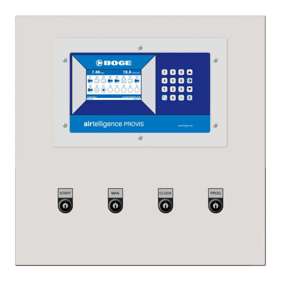
- Page 13 PROVIS Operation manual with Web-Server V 15-01-2008...
- Page 14 PROVIS combines compressors of different sizes to an optimum unit Almost the best strategy to save energy m³/min Load energy saving Load Energy - only program the compressor capacities - set the common pressure switch points - mount the pressure transducer...
- Page 15 Configuration for various speed Compressors PROGRAMMING THE COMPRESSOR CONTROL Page 6 Compressor capacities Page 7 Pressure und rank profiles Analog and Digital Inputs on airtelligence PROVIS Page 8 Page 9 Analog und Digital inputs on connection modules Page 10 Real time clock Page 11 Clock –...
- Page 16 Faults from the connection modules will be given out over the digital output „General fault of external equipment. Compressor motor running If these inputs get connected, airtelligence PROVIS receives the motor running time. The total hours are also stored as the load hours. The advertisement of the hours can be retrieved over the display. The running time compensation provides equally running times of compressors with same capacity.
- Page 17 DISPLAY and KEY CONTROL Pressure Air consumption Analog input: on Controller ▲ For indication of compressor symbols press button Function of analog inputs see Page 8 Button Function ENTER - open the Main menu ▲ Coursor upper ▼ Coursor lower ◄►...
- Page 18 VARIOUS SPEED COMPRESSOR The various speed regulated compressor is integrated actively airtelligence PROVIS He sends the information about his motor speed over his analog output to . This parameter must be programmed to the minimal and maximum capacity delivered compressed air. The analog output various speed regulated compressor inter- preted for 4-20 mA.
- Page 19 CONFIGURATION of various speed COMPRESSORS Definition REGULATION RANGE examble 4,5 m³/min examble 15 m³/min minimized Regulation range capacity m³/min 2,5-16 m³/min Regulation range Pmax Pmin Pmin Pmin Switches compressors ON / OFF if they are smaller than the regulation range regulation range Switch off with regulation buffer m³/min...
- Page 20 PROGAMMING the COMPRESSOR CAPACTIES Programming the compressor capacities m3/min Press „E“ (Enter) to open the main menu. Select the menu „programming compressor control“ to program: P R O G R A M M I N G C O M P R E S S O R C O N T R O L Compressor module (capacities) •...
- Page 21 PROGAMMING - Pressure and Rank profiles PRESSURE PROFILE 7 0 5 Menu „pressure switch points“. m3/min 4 different pressure profile can be P m i n P m a x P - a l a r m programmed. The pressure profile 2, 3, and 4 can be selected over: 6 .
- Page 22 ANALOG - INPUTS at airtelligence PROVIS ANALOG inputs on airtelligence PROVIS m3/min airtelligence PROVIS has as standart 4 analog inputs P R O G R A M M I N G C O M P R E S S O R...
- Page 23 ANALOG + DIGITAL-INPUTS of connection modules ANALOG and DIGITAL inputs Up to 8 connection modules can be m3/min connected for external analog sensors P R O G R A M M I N G A N A L O G - D I G I T A L - I N P U T S and digital potential free contacts of M A S T E R A N A L O G...
- Page 24 PROGRAMMING REAL TIME CLOCK The clock relay permits following time controlled functions m3/min • Switchung compressors ON/OFF 4 pressure profiles • P R O G R A M M I N G C O M P R E S S O R C O N T R O L 4 rank profiles •...
- Page 25 CLOCK - PROGRAMMING - NOTES Compressor chanels m³/min m³/min Pressure profile = PP P min P max P Alarm Compressor rank profile = RP Kompr. 1.RF 2.RF 3.RF 4.RF Clock relay switching times and functions Day of the week time SP=switching point LS=Management Leadsystem digital output =R1...
- Page 26 : m i n T o t a l h : m i n of operation with airtelligence PROVIS 7 5 2 3 1 : 1 6 7 5 2 4 1 : 5 9 2 8 3 6 4 : 3 2...
- Page 27 Switching ON delay time is 30 sec (default by manufacturer). Connect cable bridge “START” with an cable or a switch. airtelligence PROVIS will start your compressed air station. From now on your compressors are energy saving controlled and depending on your real consumption of compressed air.
- Page 28 PART 2 WEB-Server ONLINE Visualization Page 15 Software - Version Page 16 Programming IP-address Page 17 Web Server installation Page 18 Select data directory Page 19 User interface Page 20 OFFLINE evaluation Page 21 Select different Diagrams Page 22 Energy calculation, service and alarm report Page 23 Fundamental settings Page 24...
- Page 29 Web-based ONLINE VISUALIZATION Operation manual Version 1.08 Dated 01/2008...
- Page 30 . 1 6 8 . 0 . 1 0 0 clock in the airtelligence PROVIS S u b n e t m a s k 2 5 5 . 2 5 5 . 2 5 5 . 2 5 5...
-
Page 31: System Requirements
At the first start it can occur, an error message the Internet Explorer, because the start of the logging service needs longer than starting the airtelligence PROVIS visualization initial page. In this case wait a couple of seconds and klick in the Internet Explorer the button update. - Page 32 The process can last for some minutes This software communicates over TCP/IP For successful communication, the software has to know the IP-Address of airtelligence PROVIS You can eit the IP-Address on airtelligence PROVIS by key-combination „+/- and 8“ According to the base configuration...
- Page 33 USER INTERFACE The airtelligence PROVISWeb servers visualization has a card rider system for the basic functions. The possible respectively currently options are active (black dialable), The online visualization shows the status of the compressed air station in real time. Fault or service messages are distributed directly here. JavaPlugin 1.4.2 is necessary for the Online- functions.
- Page 34 OFFLINE EVALUATION Click „Open file: You get an overview of the saved data of the last months Select month: daily data files can be selected Weekly data: the files of the week are completly ready with daily air consumption and energy calculation Monthly data the monthly filesare completly ready with daily air consumption and energy calculation Close...
- Page 35 SELECT different DIAGRAMMS A menu can be opened on the left side of the diagram. You find all available diagrams and functions there. Over the card riders you reach the most important diagrams directly.
- Page 36 The maintenance interval can be moved back to the previous value over the „R“ button. Changes get active only Airtelligence PROVIS Alarm and Service Report after storing. Alarm and Service Report will show every fault alarms and service actions...
- Page 37 Motor power in kW • Cos phi • Temperature measuring with 4-20mA Signal. Analog inputs with 4-20mA input Signal on airtelligence PROVIS Analog inputs: Digital inputs: Alarm and Service • AE1 = net pressure Management (Option) different analog sensors any digital fault or AE2 + AE3 + AE4 •...
- Page 38 Amperé kW, price of electricity, network attitudes and receiver of alarms becomes adjusted here. The Communication listener: shows the last communication status between Web-Server and airtelligence PROVIS in case of communication error Control following control parameter can be managed: • pressure profiles compressor rank profiles •...
- Page 39 Each station must be separately updatd With „search“ you can select the software Welcome to the airtelligence PROVIS configuration assistent archives on your local hard disk With „Start update“ the archives are loaded...
- Page 40 PART 3 measurements, configuration and teminal connection plans Operating the standart housing for airtelligence PROVIS Page 27 Page 28 Master Modul drawing of measurement Page 29 Connection and teminal plan Page 30 Terminal connection scheme Page 31 Connection Module configuration...
Need help?
Do you have a question about the airtelligence PROVIS and is the answer not in the manual?
Questions and answers