Table of Contents
Advertisement
Table of Contents
Read the operator manual entirely. When you see this symbol, the
subsequent instructions and warnings are serious - follow without
exception. Your life and the lives of others depend on it!
Illustrations may show optional equipment not supplied with standard unit or
may depict similar models where a topic is identical.
ORIGINAL INSTRUCTIONS
© Copyright 1999
Table of Contents
Index
Operator Manual
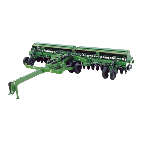
2N-2410 and 2N-3010
Folding No-Till Drill
Manufacturing, Inc.
www.greatplainsmfg.com
Printed 2018-08-02
Index
14570
EN
196-126M
Advertisement
Table of Contents

Subscribe to Our Youtube Channel
Related Manuals for GREAT PLAINS 2N-2410


Summary of Contents for GREAT PLAINS 2N-2410
- Page 1 Table of Contents Index Operator Manual 2N-2410 and 2N-3010 Folding No-Till Drill Manufacturing, Inc. www.greatplainsmfg.com Read the operator manual entirely. When you see this symbol, the subsequent instructions and warnings are serious - follow without exception. Your life and the lives of others depend on it!
- Page 2 Machine Identification Record your machine details in the log below. If you replace this manual, be sure to transfer this information to the new manual. If you or the dealer have added options not originally ordered with the machine, or removed options that were originally ordered, the weights and measurements are no longer accurate for your machine.
-
Page 3: Table Of Contents
Great Plains Manufacturing, Inc. provides this publication “as is” without warranty of any kind, either expressed or implied. While every precaution has been taken in the preparation of this manual, Great Plains Manufacturing, Inc. assumes no responsibility for errors or omissions. Neither is any liability assumed for damages resulting from the use of the information contained herein. -
Page 4: Important Safety Information
2N-2410 & 2N-3010 Table of Contents Index Important Safety Information Look for Safety Symbol The SAFETY ALERT SYMBOL indicates there is a potential hazard to personal safety involved and extra safety precaution must be taken. When you see this symbol, be alert and carefully read the message that follows it. -
Page 5: Important Safety Information
2N-2410 & 2N-3010 Table of Contents Index Important Safety Information Wear Protective Equipment Wear protective clothing and equipment. Wear clothing and equipment appropriate for the job. Avoid loose-fitting clothing. Because prolonged exposure to loud noise can cause hearing impairment or hearing loss, wear suitable hearing protection such as earmuffs or earplugs. -
Page 6: Important Safety Information
2N-2410 & 2N-3010 Table of Contents Index Important Safety Information Use A Safety Chain Use a safety chain to help control drawn machinery should it separate from tractor drawbar. Use a chain with a strength rating equal to or greater than the gross weight of towed machinery. -
Page 7: Important Safety Information
2N-2410 & 2N-3010 Table of Contents Index Important Safety Information Tire Safety Tire changing can be dangerous and should be performed by trained personnel using correct tools and equipment. When inflating tires, use a clip-on chuck and extension hose long enough for you to stand to one side–not in front of or over tire assembly. -
Page 8: Safety Decals
Refer to this section for proper decal placement. When ordering new parts or components, also request corresponding safety decals. Reflector: Slow Moving Vehicle (SMV) (2N-2410 S/N C1977-)(2N-3010 S/N D2485-) 818-055C At rear of drill when folded 12945A 1 total... -
Page 9: Important Safety Information
2N-2410 & 2N-3010 Table of Contents Index Important Safety Information Reflectors: Red 818-230C On side frames at inner ends of walkboard 2 total 68479 Reflectors: Red 838-266C On side frames at inner ends of walkboard 4 total 68479A 00000 Reflectors: Daytime 838-267C On side frames at inner ends of walkboard;... -
Page 10: Table Of Contents Index Important Safety Information
2N-2410 & 2N-3010 Table of Contents Index Important Safety Information Reflectors: Amber 818-229C On rear of walkboards at outer ends; 12943A On side frames at outer ends of walkboard; 4 total Reflectors: Amber 838-265C On rear of walkboards at outer ends;... -
Page 11: Important Safety Information
2N-2410 & 2N-3010 Table of Contents Index Important Safety Information Danger: Chemical Hazard 838-467C 13734 Inside drill box; 1 total Warning: Pinching/Crushing 818-045C 1294 2 total Warning: Transport Lock 818-477C 14526 2 total 8/2/18 Table of Contents Index 196-126M... -
Page 12: Warning: Speed
2N-2410 & 2N-3010 Table of Contents Index Important Safety Information Warning: Speed 818-188C WARNING EXCESSIVE SPEED HAZARD To Prevent Serious Injury or Death: Do Not exceed 20 mph maximum transport speed. Loss of vehicle control and/or machine can result. 818-188C Rev. C... -
Page 13: On Tongue Tube Near Hitch
2N-2410 & 2N-3010 Table of Contents Index Important Safety Information Caution: Lowering Drill 818-020C CAUTION TIRE DAMAGE HAZARD To Avoid Machine Damage: Do Not lower drill in folded position - tire damage may result. 12944A 818-020C Rev. B On tongue tube near hitch... -
Page 14: Table Of Contents Index Important Safety Information
2N-2410 & 2N-3010 Table of Contents Index Important Safety Information Caution: Tire Pressure and Torque 838-092C Gauge wheel with 265/70B16.5 NHS skid steer tire; 4 total Caution: Tire Pressure and Torque 818-855C Gauge wheel with 11L-15 X 8 PLY ribbed tire;... -
Page 15: Important Safety Information
2N-2410 & 2N-3010 Table of Contents Index Important Safety Information Caution: Tire Pressure and Torque 838-259C CAUTION Transport wheel with 12.5-15 20 ply ribbed tire; 4 total 68481 Caution: Tire Pressure and Torque 838-092C Auxiliary axle; 68481 4 total NOTICE: No Petroleum Products... -
Page 16: Introduction
2N-2410 & 2N-3010 Table of Contents Index INTRODUCTION Great Plains welcomes you to its growing family of new product owners. This implement has been designed with care and built by skilled workers using quality materials. Proper assembly, maintenance and safe operating practices will help you get years of satisfactory use from the machine. -
Page 17: Owner Assistance
Great Plains parts. Always use the serial and model number when ordering parts from your Great Plains dealer. The serial number plate is located on the outside end of the left drill box as shown in Figure 2. -
Page 18: Drill Preparation And Setup
2N-2410 & 2N-3010 Table of Contents Index Drill Preparation and Setup This section will help you prepare your tractor and drill for use. The drill hitch must be adjusted to match drawbar height, and the drill control console must be installed in your tractor. -
Page 19: Installing Drill Control Consoles
4. Hitch the drill to the tractor using a hitch pin at least one inch in diameter. Install a retaining clip on the hitch pin to prevent it from working up. A clevis-style hitch, Great Plains part number 196-136H, is available through your Great Plains dealer. -
Page 20: Bleeding Hydraulic Systems
2N-2410 & 2N-3010 Table of Contents Index Drill Preparation and Setup Bleeding Hydraulic Systems A hydraulic system with air in the circuit will move in To prevent trapped air pockets, the rod end must be higher jerky, uneven motions. If your hydraulics have not been than any other part of the cylinder. -
Page 21: Raise-To-Fold Hydraulics
2N-2410 & 2N-3010 Table of Contents Index Drill Preparation and Setup Raise-To-Fold Hydraulics the lever to feed oil to the base end of the tool-bar cylinders. Stop when you see oil coming from around The raise-to-fold cylinders are double acting but not the fittings. -
Page 22: Marker Hydraulics
2N-2410 & 2N-3010 Table of Contents Index Drill Preparation and Setup Marker Hydraulics Never allow anyone near the drill when cycling the markers. 1. Make sure the tractor hydraulic fluid reservoir is filled to the proper level. It will take one gallon to charge the dual marker cylinders. -
Page 23: Frame Leveling Adjustment
2N-2410 & 2N-3010 Table of Contents Index Drill Preparation and Setup Frame Leveling Adjustment Periodic frame leveling should not be necessary, but if you are having trouble maintaining equal coulter depth across the drill, check that the frame is level. When the drill is level, the box frames will be the same distance from the ground at both ends of the drill. -
Page 24: Aligning Boxes
2N-2410 & 2N-3010 Table of Contents Index Drill Preparation and Setup Aligning Boxes Refer to Figures 7 and 8 For proper alignment, the outside ends of the drill boxes must be 1 to 1- 1/2 inches ahead of the inside ends. -
Page 25: Operating Instructions
2N-2410 & 2N-3010 Table of Contents Index Operating Instructions This section will help you prepare the tractor and drill for use. It will also give you general operating procedures. Experience, machine familiarity and the following information will lead to efficient operation and good working habits. -
Page 26: Hitching Tractor To Drill
2N-2410 & 2N-3010 Table of Contents Index Operating Instructions Hydraulics Your tractor must have two remote outlets. Safety Lights Your tractor must be wired for the standard 7-pin electrical connector. If your tractor is not equipped with this connector, consult your dealer for installation. -
Page 27: Operating Electric Clutch Consoles
2N-2410 & 2N-3010 Table of Contents Index Operating Instructions Operating Electric Clutch Consoles To operate electric clutches, turn either the left or right clutch switch to the off position to shut down the seeding from the corresponding box. Turn the electric clutch switches off when folding or in transport. -
Page 28: Unfolding The Drill
2N-2410 & 2N-3010 Table of Contents Index Operating Instructions Once drill is folded over transport carriers, turn off fold switch. Turn on raise-to-fold switch. Work tractor hydraulic lever to lower boxes onto carriers. Turn off raise-to-fold switch. Folding Harrow Attachment Before hydraulically folding drill, fold optional coil-tine harrow as explained below. -
Page 29: Lifting The Drill In The Field
2N-2410 & 2N-3010 Table of Contents Index Operating Instructions Lifting the Drill in the Field Your drill is raised for field operations with hydraulic cylinders in a master-slave configuration. Over a period of normal use the cylinders may get out of phase. This will cause one side of the drill to run higher. -
Page 30: Opener Operation
The left-marker position controls both markers. If you wish to operate the markers independently, contact your Great Plains dealer for additional parts to modify the marker hydraulics. Markers are equipped with needle valves to set folding speed. -
Page 31: Shaft Monitor Operation
2N-2410 & 2N-3010 Table of Contents Index Operating Instructions Shaft Monitor Operation To operate the optional shaft monitors, turn the shaft- monitor switch on the control console to the on position. If either seed-cup shaft stops for 20 seconds, an alarm will sound. -
Page 32: Transporting
2N-2410 & 2N-3010 Table of Contents Index Operating Instructions Transporting 4. Remove the jack from its storage stub. Pin the jack in parking position. See Figure 9, page 23. If the ground is soft, place a board or plate under the jack. -
Page 33: Adjustments
2N-2410 & 2N-3010 Table of Contents Index Adjustments No-Till Seeding To get full performance from your no-till drill, you need a good understanding of coulter, opener and press wheel operation. Coulters. A no-till coulter is mounted independently and directly ahead of each opener. The coulters cut through heavy trash and make a groove in the soil. -
Page 34: Hydraulic Depth Control
2N-2410 & 2N-3010 Table of Contents Index Adjustments Hydraulic Depth Control Refer to Figure 11 The master field-lift cylinder on the left-hand transport Raise Coulters Raise Coulters wheel is equipped with a hydraulic valve that regulates coulter depth. Figure 11 shows the valve and knob used to adjust coulter depth. -
Page 35: Electric Clutch Switch Adjustment
2N-2410 & 2N-3010 Table of Contents Index Adjustments Electric Clutch Switch Adjustment 19711 To adjust the height at which seed metering is turned off, follow these steps. Refer to Figure 12 1. Locate the height switch at left-hand gauge wheel. -
Page 36: Pull Cable Adjustments
2N-2410 & 2N-3010 Table of Contents Index Adjustments Pull Cable Adjustments Refer to Figure 15 1. To adjust the pull cables, loosen the jam nut on the adjustment trunnion screw, and adjust the screw either in or out to move the box end forward or backwards as required. - Page 37 2N-2410 & 2N-3010 Table of Contents Index Adjustments Weight Chart, 30-Foot Drill 7 1/2-in. 8-in. 10-in. Rows Rows Rows Empty Drill, Pounds 20,100 19,600 18,400 Pounds Per Coulter, No Weights Pounds Per Coulter, Brackets and 1000 Pounds Added Optional...
- Page 38 2N-2410 & 2N-3010 Table of Contents Index Adjustments Individual Coulters Refer to Figure 17 When coulters follow in tire tracks and do not give satisfactory depth, individual coulters can be lowered by loosening the mounting clamps and adjusting the coulter to the desired setting.
-
Page 39: Opener Down-Pressure Adjustment
2N-2410 & 2N-3010 Table of Contents Index Adjustments Opener Down-Pressure Adjustment You can adjust spring down pressure individually for each opener. This is useful for penetrating hard soil and planting in tire tracks. Refer to Figure 18 To adjust down pressure, use the adjustment tool stored under the walkboard. -
Page 40: Setting The Seeding Rate
2N-2410 & 2N-3010 Table of Contents Index Adjustments Setting the Seeding Rate Calibrating the seeding rate requires four steps: shifting the speed-change gearbox, adjusting the seed-rate handle, setting the seed-cup doors, and checking the seeding rate. Check the Seed-Rate Charts or in the drill boxes. - Page 41 2N-2410 & 2N-3010 Table of Contents Index Adjustments 2. Adjust Seed-Rate Handle Refer to Figure 22 Position the handle to the setting indicated on the seed- rate chart. To adjust, loosen the wing nut under the handle and slide until indicator lines up with desired setting.
-
Page 42: Gauge-Wheel Drive Adjustment
2N-2410 & 2N-3010 Table of Contents Index Adjustments Small Seeds Attachment To set the seeding rate, refer to the Seed-Rate Charts. Move the seed-rate handle on the attachment to the setting indicated on the chart. To calibrate the attachment to your material, follow the steps listed under Check Seeding Rate, page 38. -
Page 43: Marker Adjustments
Full-Threaded Adjustment Bolt marker body with a 7/16-inch, grade 5 shear bolt. See Figure 26. If it breaks, you must replace it with a grade 5 bolt. The bolt is Great Plains part number 802-234C. 8/2/18 Table of Contents Index... -
Page 44: Disk Adjustment
2N-2410 & 2N-3010 Table of Contents Index Adjustments Disk Adjustment The aggressiveness and the mark left by the disk may be changed by two methods: Angle of Cut Refer to Figure 27 To change the angle of cut, loosen the two 1/2-inch bolts holding the disk assembly. -
Page 45: Coulter Tines
2N-2410 & 2N-3010 Table of Contents Index Adjustments Refer to Figure 30 The single-marker system is equipped with a needle valve in the hydraulic hose line at the rod end of the marker Slower Faster cylinder. Turn the adjustment knob clockwise to decrease or counterclockwise to increase folding speed. -
Page 46: Troubleshooting
2N-2410 & 2N-3010 Table of Contents Index Troubleshooting Problem Solution Check for plugging in seed cups. Uneven seed spacing Check for plugging in seed tubes. or stand Reduce ground speed. Check that opener disks turn freely. Shift speed-change gearbox to a faster drive-type and adjust the seed-rate handle to a lower number. - Page 47 Add chain slack as necessary. Refer to Marker Chain, page 40. Reverse blade to pull dirt in or throw dirt out depending on soil conditions. Refer to Disc Scraper Adjustment, page 39. An optional smooth blade is available through your Great Plains dealer. 8/2/18 Table of Contents...
-
Page 48: General Maintenance
2N-2410 & 2N-3010 Table of Contents Index Troubleshooting General Maintenance Proper servicing and adjustment is the key to long implement life. With careful and systematic inspection, you can avoid costly maintenance, downtime and Some chemicals will cause serious burns, lung damage and repair. -
Page 49: Cylinder Lock Channels
7. Check all moving and soil-contact parts for wear or damage. Make notes of any parts needing repair. 8. Use Great Plains touch-up paint to cover scratches, chips and worn areas to prevent rust. 8/2/18... -
Page 50: Lubrication
2N-2410 & 2N-3010 Table of Contents Index Lubrication Intervals (operating hours) Multi-purpose Multi-purpose Multi-purpose Inspection at which service oil lubricant spray lubricant grease lubricant is required 34208 Gauge-Wheel-Arm Pivot Castings The grease fittings are in the three-bolt cast bearings at the end of each wheel arm pivot tube. - Page 51 2N-2410 & 2N-3010 Table of Contents Index Lubrication Coulter-Arm Pivots Zerks are on central grease banks - two banks on each box. Type of Lubrication: Grease 14192 Coulter Hub Bearings Seasonal Type of Lubrication: Grease 12924 Wheel Bearings Seasonal Repack and check seals on transport and gauge wheels.
-
Page 52: Optional Attachments Lubrication
2N-2410 & 2N-3010 Table of Contents Index Lubrication Drive-TrainRoller Chain Required Type of Lubrication: Chain Lube Optional Attachments Lubrication 12227 Gauge-Wheel-to-Agitator Chains Required Type of Lubrication: Chain Lube 12227 ElectricClutch-Drive Chain Type of Lubrication: Chain Lube 13933 8/2/18 Table of Contents... - Page 53 2N-2410 & 2N-3010 Table of Contents Index Lubrication Marker Hinges Type of Lubrication: Grease 13008 Marker-Disc Bearings 2 - 3 Years If the grease seal cap is damaged or missing, disassemble and clean the hub. Repack with grease and install a new seal or grease cap.
-
Page 54: Options
In high-residue fields, the tines will help guide the residue under the coulters and openers to prevent plugging. To order tines, contact your Great Plains dealer. Refer to the table below for the correct tine package for your drill. -
Page 55: Markers
For setting the seeding rate on the attachment, refer to Check Seeding Rate page 38. To order the small seeds attachment, contact your Great Plains dealer. Refer to the table below for the correct part number for your drill. Attachment Package... -
Page 56: Harrow Attachment
The kit includes mounting hardware, boom plumbing and nozzle bodies for 20-inch spacing. Tractor tanks, pump, plumbing to the drill and nozzles are required. To order the boom, contact your Great Plains dealer. Package Part Number 116-195A... -
Page 57: Seed-Lok Firming Wheels
Seed-cup plugs are available to block off individual rows when you want wider row spacing. These plugs are installed by pushing them into the seed-cup openings on the desired rows. To order seed-cup plugs, contact your Great Plains dealer. Seed Cup Plugs Package Part Number 1 3/4 in. -
Page 58: Specifications And Capacities
2N-2410 & 2N-3010 Table of Contents Index Specifications and Capacities Transport Width 17 feet, 1 inch Working Width 24 or 30 feet Box Length 12 or 15 feet Dual Transport Tire Size 12.5L x 15 20-Ply Gauge Wheel Tire Size: 11L x 15 8-Ply 24-ft. -
Page 59: Appendix
2N-2410 & 2N-3010 Table of Contents Index Appendix Electric Clutch Console and Wire Harness Connect to tractor Leave console loose battery. Run this wire connector in the tractor cab. out the cab and to the back of the tractor. Connect to the electric clutch... -
Page 60: Torque Values Chart For Common Bolt Sizes
2N-2410 & 2N-3010 Table of Contents Index Appendix Torque Values Chart for Common Bolt Sizes Bolt Head Identification Bolt Head Identification Bolt Bolt 10.9 Size Size Grade 2 Grade 5 Grade 8 Class 5.8 Class 8.8 Class 10.9 ft-lb ft-lb... - Page 61 This Warranty is limited to the replacement of any defective part by Great Plains and the installation by the dealer of any such replacement part. Great Plains reserves the right to inspect any equipment or part which are claimed to have been defective in material or workmanship.
- Page 62 2N-2410 and 2N-3010 Cover Table of Contents Index amber ..........7 838-467C, decal ........8 daytime ......... 6 858-679C, decal .........12 accident, hydraulic ........2 red ..........6 acremeter, operation ......28 SMV ..........5 amber reflector ........7 reflectors, safety ........5 riders ............ 3 CAUTION, defined .......1...
- Page 63 Table of Contents Index Table of Contents Index...
- Page 64 Great Plains, Mfg. 1525 E. North St. P.O. Box 5060 Salina, KS 67402...
Need help?
Do you have a question about the 2N-2410 and is the answer not in the manual?
Questions and answers