Blackmagicdesign URSA Mini Installation And Operation Manual
Hide thumbs
Also See for URSA Mini:
- Installation and operation manual (1473 pages) ,
- Installation and operation manual (132 pages)
Table of Contents
Advertisement
Installation and Operation Manual
Blackmagic URSA Mini
and URSA Mini Pro
Includes Blackmagic URSA Viewfinder, URSA Studio Viewfinder,
URSA Mini Shoulder Kit, URSA Mini Lens Mounts, Blackmagic Camera
Fiber Converter, Studio Fiber Converter and URSA Mini SSD Recorder.
November 2018
日本語
English,
, Français, Deutsch, Español,
,
, Italiano, Português and Türkçe.
한국어
,
中文
Advertisement
Table of Contents

Subscribe to Our Youtube Channel
Related Manuals for Blackmagicdesign URSA Mini


Summary of Contents for Blackmagicdesign URSA Mini
- Page 1 Installation and Operation Manual Blackmagic URSA Mini and URSA Mini Pro Includes Blackmagic URSA Viewfinder, URSA Studio Viewfinder, URSA Mini Shoulder Kit, URSA Mini Lens Mounts, Blackmagic Camera Fiber Converter, Studio Fiber Converter and URSA Mini SSD Recorder. November 2018 日本語...
-
Page 2: Table Of Contents
Preparing Media on Blackmagic URSA Mini Preparing Media on Blackmagic Audio Settings URSA Mini Pro 4.6K Audio Settings – URSA Mini Preparing Media on Mac Audio Settings – URSA Mini Pro 4.6K Preparing Media on Windows Setup Settings Recording Presets Recording Clips... - Page 3 Shimming Lens Mounts Converter Shimming URSA Mini PL Interchangeable Lens Mount Shimming URSA Mini Pro 4.6K Blackmagic URSA Mini Pro PL Mount Developer Information Blackmagic URSA Mini Pro B4 Mount Blackmagic SDI Camera Control Protocol Blackmagic URSA Mini Pro F Mount...
-
Page 4: Which Camera Are You Using
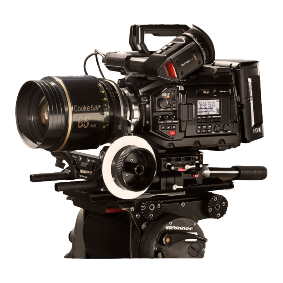
You’ll notice while reading this manual that occasionally a feature will be specific to a particular Blackmagic URSA Mini camera. All URSA Mini cameras produce incredible, wide dynamic range images and share the same basic chassis. There are some differences between different models, though. -
Page 5: Ursa Mini
URSA Mini, left side URSA Mini Pro 4.6K Blackmagic URSA Mini Pro 4.6K is a little different. This camera is only available as a 4.6K model with an EF mount, but it can accept other lens types via its interchangeable lens mount. -
Page 6: Getting Started
Attaching a Lens Attaching a lens to your camera is the same process for URSA Mini 4K, URSA Mini 4.6K and URSA Mini Pro 4.6K, however the EF, PL, B4 and F mounts have slightly different ways of operating. - Page 7 Be sure to align the lens for easy viewing of the lens marks. Tighten the PL locking ring by rotating it clockwise. If attaching a PL lens with a servo unit to URSA Mini PL or URSA Mini Pro 4.6K, you can also connect the 12 pin broadcast connector for servo control.
- Page 8 To power the lens and provide lens control, simply plug the lens cable into the connector marked ‘Lens’ on the front of your URSA Mini PL or URSA Mini Pro 4.6K's turret. Most B4 lenses will have the hirose 12 pin connector and cable built in. This will provide power and control signals from your URSA Mini to the lens.
-
Page 9: Powering Your Camera
2 o’clock position, and gently remove. NOTE Blackmagic URSA Mini Pro F mount features a mechanical iris adjuster. To use older style F mount lenses with built in focus rings with this mount, your lenses aperture will need to be set and locked to its smallest setting, such as f/22. - Page 10 Use the supplied AC to 12V DC adapter to power your Blackmagic URSA Mini You can use industry standard third party external batteries such as V mount or Gold Mount batteries with your URSA Mini. Refer to the ‘mounting batteries' section for more information about mounting the different types of battery plates to support different batteries.
- Page 11 LCD to power your camera on or off If your URSA Mini Pro 4.6K is turned off when the power switch is set to 'on', your camera may have been powered down via Bluetooth® control or by holding down the record and forward skip control panel buttons.
-
Page 12: Storage Media
Storage Media Your Blackmagic URSA Mini camera has a number of storage options. All URSA Mini cameras use CFast 2.0 cards to record video. URSA Mini Pro 4.6K can also record to fast UHS-II and UHS-I SD cards. Using the optional URSA Mini SSD Recorder, all URSA Mini cameras can record to high capacity solid state drives, or "SSDs". - Page 13 Blackmagic URSA Mini. Which CFast cards should I use with the Blackmagic URSA Mini and URSA Mini Pro Cameras? The following CFast 2.0 cards are recommended for recording 4.6K Blackmagic RAW 3:1 up to 60 frames per second.
- Page 14 Only the 'D-series' of Sandisk CFast 2.0 cards have been certified for use with Blackmagic URSA Mini. These cards can be identified by a large ‘D’ printed on the back of the card in the lower left corner, and we have also listed the model numbers to make them easier to identify.
- Page 15 The following CFast 2.0 cards are recommended for Ultra HD ProRes 422 HQ up to 60 frames per second. Brand Card Name Storage Angelbird AVpro CF XT 256GB Angelbird AVpro CF XT 512GB Cinedisk Pro 510MB/s CFast 2.0 256GB KomputerBay 3400x CFast 2.0 Card 64GB KomputerBay...
-
Page 16: Sd Cards
Blackmagic Design support center at www.blackmagicdesign.com/support. SD Cards In addition to CFast 2.0 cards, Blackmagic URSA Mini Pro 4.6K can record on high speed UHS-I and UHS-II type SD cards. Using high end SDXC UHS-II cards, you can even record ProRes HQ... - Page 17 The tables below identify the SD cards recommended for use when shooting with Blackmagic URSA Mini Pro 4.6K. It’s worth regularly checking the latest version of this manual for more up to date information. Updated manuals are available for download from the Blackmagic Design website at www.blackmagicdesign.com/support...
- Page 18 The following SD cards are recommended for Ultra HD ProRes 422 HQ up to 30 frames per second. Brand Card Name Storage Angelbird AV Pro 300MB/s UHS-II SDXC 64GB Angelbird AV Pro 300MB/s UHS-II SDXC 128GB Delkin Devices UHS-II 250MB/s SDHC 32GB ProGrade Digital V90 UHS-II 250MB/s SDXC...
- Page 19 Ultimate UHS-II 180MB/s SDXC 64GB Wise 285MB/s UHS-II SDXC 64GB Wise 285MB/s UHS-II SDXC 128GB For the most up to date information on supported SD cards for URSA Mini Pro 4.6K please refer to the Blackmagic Design support center at www.blackmagicdesign.com/support. Storage Media...
- Page 20 SD card Your URSA Mini Pro 4.6K will let you know if you've inserted a locked SD card by displaying a 'locked' icon on the LCD touchscreen and storage menu. If the card is locked, you won't be able to record video, capture stills, or export LUTs and presets until it is unlocked.
-
Page 21: Ssds
SSDs With the optional Blackmagic URSA Mini SSD Recorder, URSA Mini can record video directly to solid state drives, or ‘SSDs’. These fast, high capacity drives can are readily available from a variety of consumer electronics outlets. NOTE See the section ‘Blackmagic URSA Mini SSD Recorder’ in this manual for information on installing Blackmagic URSA Mini SSD Recorder. - Page 22 Blackmagic URSA Mini SSD Recorder SSDs The following SSDs are recommended for 4.6K lossless RAW up to 30 frames per second. Brand SSD Name Storage Angelbird AV Pro 500GB Angelbird AV Pro Mk 3 250GB Angelbird AV Pro Mk 3...
- Page 23 The following SSD’s are recommended for 4.6K ProRes 444 XQ up to 30 frames per second. Brand SSD Name Storage Angelbird AV Pro 500GB Angelbird AV Pro Mk 3 250GB Angelbird AV Pro Mk 3 500GB Angelbird AV Pro XT 500GB Angelbird AV Pro XT...
- Page 24 The following SSD’s are recommended for Ultra HD ProRes 422 HQ up to 60 frames per second. Brand SSD Name Storage Angelbird AV Pro 500GB Angelbird AV Pro Mk 3 250GB Angelbird AV Pro Mk 3 500GB Angelbird AV Pro XT 500GB Angelbird AV Pro XT...
-
Page 25: Preparing Media For Recording
URSA Mini’s storage and formatting screen, or via a Mac or Windows computer. We recommend formatting storage media using URSA Mini for best performance. HFS+ is also known as Mac OS X extended and is the recommended format as it supports 'journaling'. - Page 26 Use your URSA Mini's storage manager to format your camera's CFast cards Tap 'edit reel number' if you would like to manually change the reel number. Choose OS X Extended or exFAT format and tap the 'format card' button. Tap 'edit reel number' to manually edit the reel number You will be asked to confirm your selection.
-
Page 27: Preparing Media On Blackmagic Ursa Mini Pro 4.6K
When formatting CFast cards, SD cards or SSD's using the storage manager, your URSA Mini will use the Camera ID from the slate and reel number to name the card. Your URSA Mini automatically increments reel numbers each time you format. If you need to manually enter a specific reel number, tap the 'edit reel number' and enter the number you want to format the card as. -
Page 28: Preparing Media On Mac
Preparing Media on Mac Use the Disk Utility application included with Mac OS to format your CFast card, SD card, or SSD in the HFS+ or exFAT formats. Remember to back up anything important from your media first as all data will be lost when it is formatted. Connect the storage media to your computer using a SD card reader, dock or adapter, and dismiss any message offering to use your media for Time Machine backups. - Page 29 For lower data rates try lowering your frame rate, resolution, or try a compressed codec such as ProRes. Check the Blackmagic Design website for the latest information at www.blackmagicdesign.com Storage Media...
-
Page 30: Recording
Recording Recording Clips On Blackmagic URSA Mini you can start recording by pressing the red 'record' button on the inside control panel, the touchscreen, or the side handle. A 'record' button is also on the outside of the fold out monitor. Press the 'record' button again to stop recording. -
Page 31: Recording To Blackmagic Raw
Blackmagic RAW also includes powerful metadata support so the software reading the files knows your camera settings. If you like shooting in video gamma because you need to turn around edits quickly and you don't have time for color correction, then this metadata feature means you can select video gamma, shoot in video gamma, and the file will display with video gamma applied when you open it in software. -
Page 32: Constant Bitrate Settings
When using Blackmagic RAW in constant quality you will see the settings are Q0 and Q5. These are the compression parameters passed to the codec and they are setting how much compression is applied in a more technical way. This setting is different because the codec operates differently between constant bitrate vs constant quality. -
Page 33: Blackmagic Raw In Davinci Resolve
The Blackmagic RAW SDK supports Mac, Windows and Linux, and is available as a free download from the developer page of the Blackmagic website at www.blackmagicdesign.com/developer The following diagram illustrates the components of the Blackmagic RAW API:... -
Page 34: Choosing The Codec, Resolution And Sensor Area
Choosing the Codec, Resolution and Sensor Area Your Blackmagic URSA Mini and URSA Mini Pro 4.6K can record using CinemaDNG RAW with a choice of lossless RAW or compressed RAW, as well as Apple ProRes compressed codecs. Sensor frame rate options will vary depending on the codec and resolution you choose. - Page 35 Maximum Sensor Frame Rates The table below contains the available codecs and maximum sensor frame rates for shooting 4K, Ultra HD and HD on URSA Mini. URSA Mini Pro URSA Mini URSA Mini 4.6K 4.6K Sensor Frame Sensor Frame Sensor...
- Page 36 URSA Mini Pro URSA Mini URSA Mini 4.6K 4.6K Sensor Frame Sensor Frame Sensor Frame Resolution Codec scan Rate scan Rate scan Rate Blackmagic RAW 3:1 Window – – – – Blackmagic RAW 5:1 Window – – – – Blackmagic RAW 8:1 Window –...
- Page 37 The tables below contain available codecs, resolutions and their maximum sensor frame rates for URSA Mini 4.6K and URSA Mini Pro 4.6K models. URSA Mini Pro 4.6K URSA Mini 4.6K Resolution Codec Sensor Max Frame Sensor Max Frame scan Rate...
- Page 38 URSA Mini Pro 4.6K URSA Mini 4.6K Resolution Codec Sensor Max Frame Sensor Max Frame scan Rate scan Rate Blackmagic RAW 3:1 Window – – Blackmagic RAW 5:1 Window – – Blackmagic RAW 8:1 Window – – Blackmagic RAW 12:1 Window –...
- Page 39 URSA Mini Pro 4.6K URSA Mini 4.6K Resolution Codec Sensor Max Frame Sensor Max Frame scan Rate scan Rate Blackmagic RAW 3:1 Window Blackmagic RAW 5:1 Window Blackmagic RAW 8:1 Window Blackmagic RAW 12:1 Window Blackmagic RAW Q0 Window Blackmagic RAW Q5...
-
Page 40: Trigger Record
You will also need to set your equipment to enable SDI trigger recording to make sure it responds to the trigger signal from your URSA Mini. If your SDI equipment supports SDI trigger recording, it can usually be enabled using your SDI equipment’s settings menu. -
Page 41: Record Duration Table
256GB card. These durations are also the same for when recording to SSDs using the URSA Mini SSD Recorder. It should be noted that record duration on CFast 2.0 and SD cards can also vary slightly between cards from different manufacturers. - Page 42 16 mins 27 mins 44 mins 66 mins – 18 mins 40 mins 7 mins 18 mins Record duration table for recording on URSA Mini 4.6K and URSA Mini Pro 4.6K. 4.6K CFast Frame ProRes ProRes ProRes Blackmagic Blackmagic Blackmagic...
-
Page 43: Playback
URSA Mini's LCD touchscreen. Your clips can also be viewed on any display connected to your URSA Mini's SDI outputs. CFAST URSA Mini Camera URSA Mini Pro 4.6K Camera Blackmagic URSA Mini has playback and transport controls buttons on both the internal and ergonomic control panels. Playback... - Page 44 NOTE Blackmagic URSA Mini will play back clips of different quality settings as long as they are in the same codec, frame rate and resolution. The controls of your camera work just like a CD player, so pressing the ‘forward skip’ button will skip to the start of the next clip. Press the ‘reverse skip’ button once to go to the start of the current clip or press twice to skip back to the start of the previous clip.
-
Page 45: Introduction To Ursa Mini
XLR inputs are on the top panel behind the mounting points for professional balanced analog audio on URSA Mini and URSA Mini Pro 4.6K, and AES digital audio input on URSA Mini Pro 4.6K. A 4 pin XLR connector is provided on the rear panel for external power input, and an output is available on the right side for powering accessories such as Blackmagic URSA Viewfinder. -
Page 46: Left Side - Ursa Mini
'URSA Mini Pro 4.6K control buttons' for more information. Left Side – URSA Mini URSA Mini’s left side panel lets you insert CFast cards, access the control panel and change settings. The USB port is located just above the CFast slots so you can easily plug into a computer when updating your URSA Mini’s internal software. -
Page 47: Left Side - Ursa Mini Pro 4.6K
CFast and SD card slots are located behind the foldout monitor. The USB-C port is above these memory card slots, and is used to connect to a computer to update your URSA Mini Pro 4.6K's internal software. -
Page 48: Right Side
See the section 'storage media' for more information. Right Side URSA Mini’s right side panel gives you access to all the video, audio and power connectors plus the side handle rosette mount. URSA Mini PL model Side Rosette Mount Standard rosette mount for the side handle. -
Page 49: Rear Panel
EF lenses. 12G-SDI Out Blackmagic URSA Mini’s 12G-SDI output is used to send HD and Ultra HD video to SDI equipment such as routers, monitors, SDI capture devices, and broadcast switchers. You can also connect the 12G-SDI output to an external recorder such as the Blackmagic Video Assist for backup recording. - Page 50 Refer to the 'setup settings' in the manual for more information. On URSA Mini Pro 4.6K the SDI Input can be used for feeding external timecode to the camera as well. This will lock to the incoming timecode automatically if the frame rate of the incoming SDI signal matches and has valid timecode.
-
Page 51: Top Panel
When using URSA Mini or URSA Mini Pro 4.6K's 3.5mm jack for talkback, a very affordable option is using an iPhone or Android compatible headset. These typically feature inline button that can be used to mute and unmute their microphone. If you would like to use a broadcast headset without this inline switch you can configure your URSA Mini or URSA Mini Pro 4.6K's function buttons to offer the same functionality. -
Page 52: Ursa Mini Controls
URSA Mini Controls Your Blackmagic URSA Mini has a control panel on the left side, behind the fold out monitor and contains all the buttons and adjustment knobs you need to change settings and control audio levels. You can monitor your audio levels using the audio meters on the LCD touchscreen. - Page 53 12G-SDI input on the rear panel. This means if you’re using URSA Mini in a live broadcast, you can plug in the switcher’s program output and monitor it during the shoot. Press and hold the program button to see your program feed.
-
Page 54: Side Handle
Side Handle Your Blackmagic URSA Mini ships with a side handle that provides a comfortable, secure grip for the camera. The side handle also lets you trigger auto iris and focus on compatible EF lenses, plus start or stop recording with the simple press of a button. To enable these functions, you must connect the included LANC cable and connector between the camera and the side handle. - Page 55 D ring. Close the plastic cap. Attaching the side handle to Blackmagic URSA Mini URSA Mini is shipped with a short LANC cable so you can control your camera using the side handle buttons. Connect the LANC cable from the side handle LANC output to the camera’s LANC input.
-
Page 56: Ursa Mini Pro 4.6K Control Buttons
URSA Mini Pro 4.6K forward control panel Power Switch Power your URSA Mini Pro 4.6K by moving this switch to the ‘on’ position. Power off by moving the switch to the 'off' position. You can also power your URSA Mini Pro 4.6K on or off via a combination of control panel switches. - Page 57 ND Filters Your URSA Mini has three internal neutral density filters. Together with a clear filter, the available settings are ‘2,’ ‘4’ and ‘6’ stops. These filters allow you to reduce the amount of light reaching your URSA Mini’s sensor by a preset number of exposure 'stops'.
- Page 58 Menu Wheel When 'status text' is turned on for your URSA Mini's front SDI output, you can use the menu wheel to navigate many of the head up display features usually accessed via the LCD touchscreen. Simply press the menu wheel as you would a button to access your URSA Mini Pro 4.6K's head up display on an external monitor such as Blackmagic SmartView, Video Assist or URSA Viewfinder.
-
Page 59: Ergonomic Control Panel
Use the HFR or ‘high frame rate’ button to toggle off speed frame rates. To use this button, simply set the off speed frame rate you’d like to use in your URSA Mini Pro 4.6K’s ‘frame rate’ menu. Pressing this button will toggle between your chosen off speed frame rate and project frame rate. - Page 60 LCD status display and monitor speaker by using this switch. Lock Use this switch to lock all of the settings on your URSA Mini Pro 4.6K's ergonomic control panel. The only controls that will remain active while the lock switch is 'on' are the monitor channel select switches.
- Page 61 'timecode' button underneath the status LCD. Battery indicator If your URSA Mini Pro 4.6K is running on battery power, this indicator displays remaining battery life in 25% increments. Each of the battery indicator’s four bars corresponds to 25% battery life remaining. When your battery drops below 20% charge, the color of the status LED, near the record button begins to flash.
- Page 62 Card Information The ‘card 1’ and ‘card 2’ indicators will appear on your URSA Mini Pro 4.6K’s status LCD when these slots are occupied. The ‘SD’ indicator appears if you are recording on SD cards, and disappears if you are recording on CFast cards.
- Page 63 ‘S001’ representing the ‘still number’ as the last four digits of the filename. To confirm you have successfully saved a still, an image of a camera will show in the top right corner of the URSA Mini touchscreen and the record indicator on the status LCD will flash three times.
- Page 64 When the lens is focused, the square will disappear. NOTE Some lenses have both manual and auto focus modes. In order for URSA Mini to be able to auto focus with your lens, you need to ensure that your lens is set to auto focus mode. Program The program button is marked PGM and lets you switch the LCD between the camera view and any signal plugged into the 12G-SDI input on the rear panel.
-
Page 65: Internal Control Panel
Internal Control Panel With your URSA Mini Pro 4.6K's foldout monitor open, you can access the internal control panel. Use the controls here to set your audio inputs as well as phantom power settings, iris, focus, menu and playback controls and more. - Page 66 NOTE Some lenses have both manual and auto focus modes. In order for URSA Mini to be able to auto focus with your lens, you need to ensure that your lens is set to auto focus mode. Peak Press the ‘Peak’ button to activate focus peaking. Your camera has two focus peaking...
- Page 67 XLR 2 NOTE You can power your URSA Mini Pro 4.6K on or off via a combination of internal control panel buttons. Holding the ‘rec’ and 'forward skip' buttons will power up the camera if it is turned off, or power it off if it is turned on. If your camera’s power switch is set to ‘on’...
-
Page 68: Touchscreen Controls
Your Blackmagic URSA Mini’s fold out LCD touchscreen pivots for shooting high and low angles. Buttons on the outside of the LCD panel let you control your URSA Mini when mounted on your shoulder using the URSA Viewfinder and the LCD closed. - Page 69 To toggle focus assistance for the LCD touchscreen, tap the switch icon in the bottom left of the screen while in the ‘focus assist’ tab. To set the level of focus assistance for all outputs on your URSA Mini, tap the ‘low,’ ‘medium’ or ‘high’ titles along the bottom of your touchscreen.
- Page 70 Tap the 'frame guides' icon while accessing 'LCD monitor options' to access your URSA Mini's frame guide settings To toggle the appearance of frame guides on your URSA Mini's LCD touchscreen, tap the switch icon in the bottom left of the screen.
- Page 71 The ‘grids’ setting toggles the appearance of a rule of thirds grid, crosshair or center dot on the LCD touchscreen, as well as setting the overlay that will be visible on all URSA Mini outputs. Tap the 'grids' icon while accessing 'LCD monitor options' to access your URSA Mini's grid settings Grids and crosshairs are overlays that can help with image composition.
- Page 72 To set which overlay you want to display on all URSA Mini outputs, tap the ‘thirds,’ ‘crosshairs,’ or ‘center dot’ options. The rule of thirds grid automatically scales to any on screen frame guides ‚ Thirds The ‘thirds’ setting displays a grid with two vertical and horizontal lines placed in each third of the image.
- Page 73 ‘safe area guides’ tab. To set the level of safe area guides for all outputs on your URSA Mini, tap the left or right arrows on either side of the current numerical value at the bottom of your touchscreen. Alternatively, you can drag the slider left or right.
- Page 74 ND Filter indicator Adjusting your URSA Mini Pro 4.6K's ND filter will display the ND filter indicator in the top left of the LCD touchscreen and any SDI outputs set to show status text. This indicator will be shown for four seconds and use the format you've selected in your URSA Mini Pro 4.6K's setup menu.
- Page 75 By default, your URSA Mini’s project and sensor frame rates are matched for a natural playback speed. However, by tapping the ‘off speed frame rate’ switch icon in the bottom right hand side of your URSA Mini’s ‘FPS’...
- Page 76 URSA Mini’s shutter values or configure shutter priority auto exposure modes. On URSA Mini 4.6K and URSA Mini Pro 4.6K, the shutter measurement setting can be used to select whether to display shutter information as 'shutter angle' or 'shutter speed'.
- Page 77 The manual shutter keypad allows you to type in any shutter value you wish Your URSA Mini has three shutter based auto exposure modes. To select one of these, tap the 'auto exposure' button in the far right of the shutter menu.
- Page 78 If you are using a B4 or PL lens connected via the broadcast 12 pin connector on URSA Mini PL, make sure that the lens iris switch on the handgrip is set to ‘A’ or ‘auto.’...
- Page 79 URSA Mini EF. Duration Display At the top of your URSA Mini LCD touchscreen, you’ll see your camera’s duration display. Your URSA Mini's duration display. This will turn red while recording The duration display provides a timecode counter for checking the duration of your clips and monitoring timecode during recording and playback.
- Page 80 The ‘ISO’ indicator displays your URSA Mini’s current ISO setting, or light sensitivity. Tapping this indicator lets you adjust your ISO to suit varying lighting conditions. The optimum ISO for URSA Mini 4K is 400. The optimum ISO for URSA Mini 4.6K and URSA Mini Pro 4.6K is 800.
- Page 81 Many of your URSA Mini’s white balance presets include some tint. Tapping the white balance and tint indicator on your URSA Mini gives you access to five presets, as well as a white balance indicator and slider on the left, and a tint indicator on the right.
- Page 82 Power Your URSA Mini’s power status is displayed in the top right of the LCD screen. There are four possible indicators: Your URSA Mini's power indicator is at the top right of the LCD touchscreen. While using battery power, tapping this toggles between 'voltage' and 'percentage' displays Displayed when your URSA Mini is plugged into mains power.
- Page 83 Record button Next to the histogram at the bottom of your URSA Mini’s touchscreen, you’ll see a round gray button. This is the ‘record’ button. Tap this once to begin recording, and tap it again to stop. While recording, the button and the timecode at the top of your URSA Mini touchscreen will turn red.
- Page 84 This menu displays the amount of free space on each CFast card, SD card or SSD currently in your URSA Mini, as well as the name of the card or drive, length of the last clip, total number of clips, and the file format for each card or drive.
- Page 85 Double tap to zoom You can magnify any part of your URSA Mini's preview image by double tapping the LCD touchscreen. The area you tap will be magnified, and you can move around the image by dragging your finger around the LCD touchscreen.
- Page 86 URSA Mini LCD touchscreen Playback Menu Tap the ‘play’ control button on your URSA Mini to access the playback menu. You can control previously recorded clips with your camera’s control buttons or the LCD touchscreen. When using the LCD touchscreen, tap ‘play’ once to start playback and again to pause. Use the forward and reverse buttons just as you would on a CD player.
- Page 87 Tapping the 'record' control button in playback mode will return your camera to 'standby' mode, ready to record. Swipe up or down on your URSA Mini’s touchscreen to hide status text while playing back footage. Entering the slate in playback mode will allow you to mark the current clip ‘good take’...
-
Page 88: Settings
Pressing the ‘menu’ control button on your URSA Mini will bring up your camera's dashboard. This is a tabbed menu containing the settings not available from your URSA Mini's head up display. Settings are divided by function into ‘record,’ ‘monitor,’ ‘audio,’ ‘setup,’ ‘presets,’ and ‘LUTS’... - Page 89 Codec and Quality The ‘codec and quality’ menu is split into two rows. The top row on all URSA Mini models lets you choose between ProRes and CinemaDNG. On URSA Mini Pro 4.6K you can also select Blackmagic RAW. The bottom row offers quality options within those families, for example, the quality options available within the CinemaDNG codec family are ‘lossless’, ‘3:1’...
- Page 90 'monitor' settings later in this manual. Window Sensor URSA Mini can be set to use the ‘full’ sensor area. Alternatively, for even higher frame rates you can use ‘window’ mode. This will use only the amount of sensor pixels needed for a given video format rather than downscaling images from the entire sensor.
- Page 91 Preferred Card for Recording Use this setting to select which storage card or drive your URSA Mini will record to first when both slots are in use. The options are ‘card 1,’ ‘card 2,’ and 'fullest card'. When using an SSD the options will be 'Card 1', 'SSD' and 'fullest card'.
- Page 92 Blackmagic URSA Mini lets you record CinemaDNG RAW clips at higher frame rates by recording to both CFast cards simultaneously. When this setting is enabled your URSA Mini will record to both cards when available. If only one CFast card is inserted, your camera will attempt to record at the chosen frame rate to the single card.
-
Page 93: File Naming Convention
Detail Sharpening Use this setting to sharpen your URSA Mini’s image. When sharpening is enabled, decrease or increase the level of sharpening by selecting ‘default’, ‘medium’ or ‘high’. When sharpening is enabled, it will be applied to ProRes video recorded on camera as well as your URSA Mini’s SDI output. -
Page 94: Monitor Settings
‘LCD’, ‘front SDI’ and ‘main SDI’, as well as ‘all,’ which covers monitor settings that affect all outputs on your URSA Mini. Each of these menus has two pages of options, which you can cycle through by tapping the arrows at the edge of your camera’s touchscreen, or swiping left or right. - Page 95 LUTS, disable the ‘display LUT’ switch in the ‘Monitor’ menu for that output. Display 3D LUT Your URSA Mini can apply 3D LUTs to any output to approximate the look of color graded footage. This is especially useful when shooting with ‘film’ dynamic range, as these produce an intentionally ‘flat’...
- Page 96 Status Text On/Off This setting is only available for URSA Mini Pro 4.6K. It can be useful to hide the status text and meters on your LCD HUD, leaving only the information necessary to compose or direct a shot.
- Page 97 URSA Mini’s LCD touchscreen. Front SDI and Main SDI Monitor Settings 2 The second page of your URSA Mini's 'front SDI' and 'main SDI' monitor tab contains settings unique to your front and main SDI outputs. 2160p and 1080p resolutions are available on your main SDI output as all times when shooting at resolutions above 3K anamorphic.
- Page 98 Your URSA Mini can display director specific status text on its front and main SDI outputs Setting the status text to ‘director’ in your URSA Mini’s 'front SDI' or 'main SDI' monitor settings changes the status text for that output to show the following information.
- Page 99 For example, setting 'safe area guide %' to 90% in this menu will set the safe area guide to 90% for your camera's LCD, front SDI and main SDI outputs. There are two pages of 'all' settings. The first page of your URSA Mini's 'all' monitor tab contains the following settings.
- Page 100 Focus Assist Your URSA Mini camera has two focus assist modes, ‘peak’ and ‘colored lines.’ Peak ‚ When ‘peak’ style focus assist is selected, areas of the shot that are in focus are heavily sharpened on your LCD touchscreen or SDI outputs, but not in the recorded image itself.
- Page 101 Safe Area Guide % To adjust the size of the safe area overlay on your URSA Mini’s LCD touchscreen, front SDI and main SDI outputs, tap the arrows to the left and right of the percentage displayed in this setting. This percentage indicates the size of the safe area in relation to the image frame.
-
Page 102: Audio Settings
This slider adjusts the output levels for headphones attached to URSA Mini’s 3.5mm headphone jack. Move the audio slider left or right to adjust levels. Speaker Volume This slider adjusts the output levels for your URSA Mini’s built in speaker. Move the audio slider left or right to adjust levels. Camera Internal Mic This slider adjusts the recording levels for your URSA Mini’s built in microphone. - Page 103 Move the audio slider left or right to adjust levels. Speaker Volume This slider adjusts the output levels for your URSA Mini’s built in speaker. Move the audio slider left or right to adjust levels. Channel 1 and 2 input Set the external audio input levels by tapping ‘line’...
-
Page 104: Audio Settings - Ursa Mini Pro 4.6K
Channel 1 and 2 phantom power Your URSA Mini’s XLR inputs can provide 48V phantom power so you can use microphones that aren’t self powered. When your camera is set to ‘XLR’ audio input, simply tap the ‘phantom power’... - Page 105 XLR input may be listed as 'mic,' 'line,' or 'AES.' If phantom power is enabled and you have your XLR input set to 'mic' you'll also see a '+48V' indicator here. On URSA Mini Pro 4.6K, it is important to ensure that the 48V switch gets turned ‘off’ when you disconnect your phantom powered microphone.
-
Page 106: Setup Settings
Speaker Volume This slider adjusts the output levels for your URSA Mini’s built in speaker. Move the audio slider left or right to adjust levels. These levels will also update when you adjust the speaker volume using the settings wheel on the forward control panel. - Page 107 Set your URSA Mini’s date and time by tapping the ‘date and time’ setting. The date format is year, month, day and the time format is 24 hour. Your URSA Mini's date and time are also used for time of day timecode if an external timecode source is not connected.
- Page 108 NTSC frame rates. Display ND Filter As Use this setting to adjust how the ND filter indicator on your URSA Mini Pro 4.6K displays your ND filter setting. Each setting corresponds to a different camera convention. Cinematographers typically use ND.number notation, while those familiar with DSLRs or broadcast cameras may...
- Page 109 100%. Reference Source This setting is used to select the reference source. Your URSA Mini can lock to an internal or external reference source, or to the reference signal in program input from an ATEM switcher. If you are using your URSA Mini with an ATEM Switcher’s camera control function, you should always set your reference source to ‘program’...
- Page 110 The third page of your URSA Mini's 'setup' tab contains the following settings Set Function Button On the outside of your URSA Mini’s LCD touchscreen, you’ll notice two function buttons, ‘F1’ and ‘F2.’ These are mappable to frequently used features and are quickly accessible when using your camera with the LCD touchscreen closed, such as when you are using URSA Viewfinder.
- Page 111 To set these buttons, select a function button and then its behavior, a setting, and a parameter for that setting. Button Behavior Setting Parameter Function 1/2 Behaves as Once you have selected the function button you want to map, you can select a behavior. The available options are: ‚...
- Page 112 The fourth page of your URSA Mini's 'setup' tab contains the following settings. Door LED Your URSA Mini has a small LED on the outside of the LCD touchscreen that provides tally and status information. You can enable or disable it by tapping the ‘Door LED’ switch icon. The LED for tally and status information is located in the forward control panel on URSA Mini Pro 4.6K,...
- Page 113 LUTS and presets currently stored on the camera. Tap ‘reset’ on the confirmation page to reset your camera settings. On URSA Mini Pro 4.6K, this process can take up to two minutes to complete.
- Page 114 Bluetooth devices up to 30 feet away. Because URSA Mini Pro 4.6K uses the same set of commands for Bluetooth control as it does for 'Blackmagic SDI Camera Control Protocol', you can write your own applications to control almost every setting in the camera remotely, from monitoring to audio settings, the camera’s...
- Page 115 Enable Bluetooth by tapping the ‘Bluetooth’ switch icon in the ‘setup' menu on your URSA Mini Pro 4.6K. Open the ‘Blackmagic Camera Control App’ and select the URSA Mini Pro 4.6K you would like to pair with. Available cameras will be listed by their camera letter, followed by their unique hardware ID.
- Page 116 The information on the screen will confirm that your URSA Mini Pro 4.6K is now paired with your iPad. If there is a problem pairing the camera to your iPad you will see the following error message. NOTE If you are not using Bluetooth to control your URSA Mini Pro 4.6K, it is a good idea to turn Bluetooth off for the purpose of security.
- Page 117 Use this setting to disconnect your URSA Mini Pro 4.6K from the iPad it is currently paired with. Clear Paired Devices Use this setting to clear the list of devices that your URSA Mini Pro 4.6K has been paired with. Controlling Your Camera with the Blackmagic Camera Control App Once you have successfully paired your URSA Mini Pro 4.6K to your iPad, you can power the...
-
Page 118: Presets
You can power off your URSA Mini Pro 4.6K by tapping 'power off' in the top right corner. You will be prompted to confirm your selection before your camera is powered off When Bluetooth is enabled and URSA Mini Pro 4.6K is powered off, the name of your camera will still show up on the list of available devices in the Blackmagic Camera Control App. - Page 119 LCD touchscreen where you can name your preset. Once you’ve typed in the name, tap ‘update’ to save all of your URSA Mini’s current settings to that preset. If your URSA Mini already has a preset loaded with the same name, you will be prompted to overwrite the existing preset or keep both.
- Page 120 Use the storage media selection switch on URSA Mini Pro 4.6K to select either SD or CFast, depending on the location you would like to export the preset to. If you are using URSA Mini SSD Recorder, you can also export presets to an SSD. Tapping ‘export selected preset’ will prompt you to choose which card you would like to export to.
-
Page 121: Luts
It is easy to create 3D LUTs using DaVinci Resolve or other color correction software, and LUTs are available online from a variety of sources. Your URSA Mini can store up to six 17 point or 33 point 3D LUTs, of up to 1.5 megabytes each. Once loaded, you can choose to display a given LUT on your camera's LCD touchscreen, front SDI, main SDI or any combination of... - Page 122 LUTs are saved. You can also import LUTS stored on an SSD if you are using URSA Mini SSD recorder. Choose ‘card 1’ or ‘card 2’ at the top left of this screen to display any available 3D LUTs on those cards.
- Page 123 Deleting LUTS Your URSA Mini has space for six 17 point or 33 point 3D LUTs. To delete LUTs you are no longer using, or make room for more, select the LUTs you want to delete and tap the icon. You will be prompted to confirm your choice.
-
Page 124: Entering Metadata
VFX assets to plates. Your Blackmagic URSA Mini automatically saves some metadata to each clip, such as camera settings, timecode, date and time. You can use your camera’s slate to add many additional details. - Page 125 Slate for This setting shows the clip which the metadata currently displayed in the ‘clip’ applies to. In ‘standby’ mode, this refers to the next clip that will be recorded. Lens Data These settings display information about the current lens fitted to your camera. Many electronic lenses automatically supply information such as the lens model, aperture and focal length.
- Page 126 ‚ Focal length Shows the focal length setting of the lens at the start of the recorded clip. When automatically supplied, this is shown in millimeters. Tap this setting to enter data manually. ‚ Distance Shows the focus distance settings of the lens for the recorded clip. Some lenses can provide this data automatically and it will be provided in millimeters.
- Page 127 For example 23A would indicate scene twenty three, shot one. If you have a shot letter added to your scene, your URSA Mini will suggest letter increments whenever you enter the scene number editor. For example, if your current scene number is 7B, your URSA Mini will offer ‘7C’ as an increment suggestion.
- Page 128 When entering 'scene' metadata, your URSA Mini will prompt you with increment suggestions to the left of the touch keyboard, and shot types to the right Take The ‘take’ indicator shows the take number for the current shot. You can increment this up or down by tapping the left or right arrows on either side of the take number, or tapping the indicator to enter the take number editor.
- Page 129 Tap the ‘good take’ indicator to flag good takes for easy recall in post production. This tag applies to either the last clip recorded, if your URSA Mini is in ‘standby’ mode, or the clip currently being viewed in ‘playback’ mode.
-
Page 130: Using Servo Zoom Lenses
Some B4 and PL lenses also have handgrips with electronic focus servo. To ensure this is functioning with URSA Mini PL or URSA Mini Pro 4.6K, and able to be controlled electronically, set the switch under the zoom rocker labelled ‘focus’ to ‘S’ for servo. - Page 131 EF mount. The zoom rocker for these lenses are able to be powered through the lens mount from URSA Mini EF and URSA Mini Pro 4.6K and information such as lens name, iris, focus and zoom position values are all able to be read and recorded by URSA Mini's lens metadata system.
-
Page 132: Camera Video Output
When connected to a switcher, you can easily view the switcher’s program output on your Blackmagic URSA Mini. To do this, first connect the switcher to your camera’s rear 12G-SDI input. Now press and hold the 'program' button marked PGM on your camera's fold out monitor to view your program feed. - Page 133 Connecting to Monitors SDI monitoring can be really handy when accessing the fold out monitor is impractical, such as when secured high on a jib arm, on a crane, or mounted on a vehicle. Monitoring information is displayed via your HD-SDI monitoring out connector by adjusting the ‘front SDI overlay’...
-
Page 134: Ursa Mini Shoulder Mount Kit
URSA Mini Shoulder Mount Kit Attaching the shoulder mount The URSA Mini Shoulder Mount Kit lets you carry URSA Mini on the shoulder for ENG style shooting. This kit includes a top handle, shoulder mount baseplate, extension arm for the URSA Mini side handle, long LANC cable, Viewfinder adapter plate, plus all the required screws. - Page 135 Gently place your URSA Mini upside down on a flat, stable surface so you can easily access the base of your camera. Fasten the shoulder mount baseplate to URSA Mini using the 2 x ¼” flat head screws and driver.
- Page 136 Viewfinder position Fasten the URSA Viewfinder adapter plate to the Fasten the handle to any two of URSA Mini’s top handle using the 4 x M3 screws with a 2.5mm Hex 1/4” mounting points using the two supplied 1/4”...
- Page 137 LANC cable to move the side handle to a more ergonomic position. To attach the side handle extension arm: Place your URSA Mini on a flat, stable surface allowing room next to the camera to lower the extension arm. Mounting URSA Mini to a tripod is helpful for this purpose.
-
Page 138: Blackmagic Ursa Viewfinder
For example, if you select the ‘2.40:1’ frame guide option in URSA Mini's menu, it will actually tell the viewfinder which frame guide is selected in the camera so when you toggle the frame guide display on the viewfinder, the same ‘2.40:1’... -
Page 139: Adjusting The Eyepiece
Connect your viewfinder’s SDI and power cables to your URSA Mini HD-SDI monitoring output and +12 volt output When using the URSA Viewfinder with URSA Mini, it is highly recommended that you also install the URSA Mini shoulder mount kit as this provides the correct mounting points, 1/4” thumb screw, and height adjustments to optimize the positioning of your viewfinder. -
Page 140: Menu Settings
The buttons also have a customizable function feature so you can assign shortcuts to quickly enable common features you may use frequently. For example you may wish to assign the false color feature to the zoom button. Refer to the ‘shortcuts’ section for more information. ZOOM (F1) - ‘menu’... - Page 141 Meters Switches between the types of meters to display in overlay view. The options are ‘histogram’, ‘audio’, ‘both’ or ‘none’. Peaking Switches peaking on and off. Zebra Switches zebra levels on and off. Set your desired zebra levels using the camera settings.
- Page 142 Grid Toggles the appearance of a rule of thirds grid, crosshair or center dot. When 'grids' are turned 'on' in your URSA Mini's 'front SDI' monitor settings, you can use this setting toggle their appearance in your Blackmagic URSA Viewfinder. For more information, see the 'Monitor Settings' section in this manual.
- Page 143 Toggles the appearance of status text, such as white balance, frame rate and ISO. When 'status text' is turned 'on' in your URSA Mini's 'front SDI' monitor settings, you can use this setting toggle its appearance in your Blackmagic URSA Viewfinder.
- Page 144 need to be powered when updating, so we recommend keeping the viewfinder connected to your URSA Mini during the update process. This also means your URSA Mini will need to supply consistent power, so be sure to plug into external power.
-
Page 145: Blackmagic Ursa Studio Viewfinder
Blackmagic URSA Studio Viewfinder is a powerful viewfinder that allows you to turn your Blackmagic URSA Mini into a professional live production camera. The studio viewfinder features a bright 7” screen and has a large easily viewable tally light, control knobs, large handles, sun hood and variable tension articulated mount. -
Page 146: Mounting And Connecting To Blackmagic Ursa Mini
URSA Mini via the supplied V-lock mount plate which can be easily removed from the top handle mount. Unscrew the V-lock plate from the URSA Mini handle mount using a 3/16 Hex key, and then attach it to the top of the camera with the supplied 1/4” screws. As this will make the center of gravity on the camera much higher. - Page 147 Blackmagic URSA Studio Viewfinder mounted V-Lock mount plate being attached to to shoulder mount kit 3rd party camera The V-Lock mount plate can also be installed on any camera you want to use the URSA Studio Viewfinder with that has 1/4” mounting points, or by using a third party cheese plate. You can also mount the Blackmagic URSA Studio Viewfinder to a third party camera system that has an existing V-lock mount plate as many of them have this quick release plate on them already.
-
Page 148: Adjusting The Blackmagic Ursa Studio Viewfinder
Note that there are cable clamps on the side of the URSA Mini handle mount to keep you cables neat and hold the SDI and 12v power connections on URSA Mini cables in place. The URSA Studio Viewfinder uses open standard SDI and broadcast 4 pin XLR power connections so it can be used with any other camera or even as an adjustable portable location monitor. - Page 149 These tension dials have a very large range of tension adjustment, allowing you to select a specific amount of resistance. This allows you to easily pan and tilt the viewfinder to the precise position you require. Tension dials on either side of the viewfinder Tilt Lock Dial Locks the angle of tilt on the viewfinder mechanism.
- Page 150 Sun hood The sun hood helps you to see the screen in bright or sunny conditions. To attach the sun hood, slide it over the top of the Blackmagic URSA Studio Viewfinder and push it into place, securing it with the two captive screws on the base of the sun hood. The top section of the visor is adjustable, and can raise and lower to provide additional viewing angles.
-
Page 151: Button Features
As with URSA Mini ON/OFF switch you have the option of ‘red’, ‘green’, Switches the Blackmagic URSA ‘blue’, ‘black' and 'white' lines which... - Page 152 When using the Blackmagic URSA Studio Viewfinder with an ATEM switcher, it is important to select ‘clean feed’ on URSA Mini to ensure that you don't see overlays or the focus box on the SDI output to the ATEM switcher. Navigate to the 'monitor' menu on URSA and select ‘clean feed’...
-
Page 153: Menu Settings
Switches zebra levels on and off. The level of zebra will be determined by the setting on your URSA Mini, in the 'All' section of the 'Monitor' menu. When the Studio Viewfinder is not connected with URSA Mini, the zebra level will represent 95% of the luminance levels of a Rec 709 signal. - Page 154 Guides This setting gives you the option to show or hide your guides. The guides will match the style of guides that have been set in the URSA Mini in the camera 'all' section of the 'monitor' menu. The aspect ratio, frame guide opacity level, safe area percentage, and the type of grids shown will match what you have set in the camera.
- Page 155 Once you have set up your shortcuts as required you can either scroll to ‘exit’ and press the ‘menu’ dial to close the menu display view, or hit the back button to exit out of the menu. The 'shortcuts' submenu Setup The ‘setup’...
- Page 156 Gives you the option to show 'frame guides' as part of your Studio Viewfinder’s ’Guides’. When connected to URSA Mini they will match your camera’s 'frame guides' aspect ratio. When connected to other systems they will default to the 14:9 aspect ratio.
- Page 157 You also have the option to reset the cursors to their default state. Using a headset with the Blackmagic URSA Studio Viewfinder When using the Blackmagic URSA Studio Viewfinder with URSA Mini, the headphone connection on the camera will now become a talkback headset connection, allowing for direct communication with the director.
-
Page 158: Mounting Batteries
If you don’t have an off the shelf battery plate designed for Blackmagic URSA or URSA Mini and you want to modify your own battery plate, then you can use the supplied adapter cable and connector. -
Page 159: Using Your Own Battery Plate
Using your own Battery Plate Adapter Cable and Connector If you don’t have an off the shelf battery plate designed to plug into URSA Mini and want to modify your own battery plate, you can use the supplied adapter cable and connector, which is also available at your local Blackmagic Design support office. - Page 160 Batt Batt Batt Batt Monitor0 Monitor 1 +12V Out 11 EnableN The rear view of the adapter’s connector housing. Refer to the wire configuration table for a description of each pin Wire Configuration Table Pins Signal Color Direction Description 1, 2, 3, 4 Batt To URSA 12 V to 20 V...
-
Page 161: Blackmagic Fiber Converters
Blackmagic Studio Fiber Converter Blackmagic Camera Fiber Converter Blackmagic Studio Fiber Converter Mounts to the back of your URSA Mini This converter converts the optical fiber SDI or URSA Broadcast and connects to the signal from the camera unit to SDI via BNC,... -
Page 162: Getting Started With Blackmagic Fiber Converters
Getting Started with Blackmagic Fiber Converters Getting started is fast and efficient. It won't take long before you are producing video content and enjoying the benefits of SMPTE fiber. About SMPTE Fiber SMPTE fiber cables provide you with a simplified way to carry multiple signals as well as power, over long distances. - Page 163 Connect the rubber cap from each end of the SMPTE fiber cable into the rubber cap on each converter to prevent any dust or debris from entering the caps. One of the main benefits of using a SMPTE fiber connection is to connect to the control room or broadcast truck in a traditional live broadcast environment.
-
Page 164: Connecting Smpte Fiber
Connecting SMPTE Fiber The next step in getting started is to connect the SMPTE fiber cable between the studio fiber unit and the camera unit. This provides power from the studio unit to the camera unit, and fiber for all video feeds. NOTE Extensive safety checks are initiated whenever a powered hybrid fiber optic cable is plugged into the converter and the power safety of the unit is continually... - Page 165 Once plugged in, it is a good idea to connect the rubber cap from the end of the SMPTE fiber cable into the rubber cap from the Blackmagic Studio Fiber Converter. This will prevent any dust or debris from entering the caps, and ensure that the caps remain clean. Connecting the Fiber Cable to the Camera Unit The female end of the SMPTE fiber cable locks into the male connector on the side of Blackmagic Camera Fiber Converter, ensuring that the cable is not accidentally disconnected...
- Page 166 POWER TALLY FIBER RET 1 RET 2 LIGHT FOCUS PGM 1 PGM 2 PGM 1 PGM 2 INCOM INCOM PROD PROD IRIS INTERCOM 1 INTERCOM 2 TRACKER DC OUT AES/EBU AES/EBU LINE LINE +48V +48V SDI OUT Pinch the rubber around the tip of the cable to reveal the red ring below, then pull the cable to disconnect NOTE The SMPTE hybrid fiber cable is the heart of the broadcast ecosystem,...
- Page 167 Power Safety Considerations The SMPTE hybrid fiber optic cable is capable of carrying high voltage over long distances so that you can power a camera and accessories that are located up to 2km away. To ensure safe operation, your Blackmagic Studio Fiber Converter has safety mechanisms built in to ensure accurate monitoring and automatic management of the voltage being carried.
-
Page 168: Why Connections On The Front
Confirming Video You can now check that video is working and all return feeds are present. Ensure the ATEM switcher's program output is connected to the studio unit's SDI return input 1. If you want to check all return feeds, plug video sources into SDI return inputs 2 and 3. Now plug an SDI monitor, such as a Blackmagic SmartView 4K, into the 'SDI out' on the side panel of the camera unit. -
Page 169: Plugging In Camera Sdi
2160p60 are down converted to 1080p at the equivalent frame rate. Mounting Blackmagic Camera Fiber Converter Blackmagic Camera Fiber Converter mounts to the back of URSA Mini and URSA Broadcast directly behind the camera body, and connects to your camera’s rear SDI in and SDI out BNC connectors. - Page 170 Before installing Blackmagic Camera Fiber Converter you should check that URSA Mini’s internal software is version 4.4 or above and URSA Broadcast is 4.6 or above. You can check your software version on page 4 of the camera's 'setup' menu.
- Page 171 However, if you are operating the unit sitting flat on a surface it is a good idea to attach the URSA Mini shoulder mount pad, or third party baseplate or bridge plate as this will maintain the cooling fan's air flow in the underside of the Fiber Converter.
-
Page 172: Attaching The Ursa Studio Viewfinder
Attaching the URSA Studio Viewfinder The attached V-lock plate on the top of the unit lets you connect a Blackmagic Studio Viewfinder. This positions the studio viewfinder directly at the eye level when the camera is mounted on a pedestal or tripod. The V-Lock mount on the top of the camera unit lets you mount the Blackmagic URSA Studio Viewfinder Plugging in a Talkback Headset... -
Page 173: Operating The Camera Fiber Converter
Operating the Camera Fiber Converter Selecting a Return Feed The two return buttons on the front panel can be used in the same way as the PGM button on the camera, to switch the feed on the LCD, Blackmagic URSA Studio Viewfinder and HD monitoring outputs between the camera view and program return view. -
Page 174: Using Talkback
Using Talkback The two female 5-pin XLR connectors allow you to plug in two headsets, so that you and another crew member can have communication with the rest of the crew simultaneously. The intercom controls for each headset are grouped into two sets for two independent intercoms, and are effectively three way audio mixers for each headset XLR connector that is directly below. -
Page 175: Status Indicators
Status Indicators The 'power', 'tally' and ‘fiber' status LEDs at the top of the converter will illuminate different colors depending on the status of the unit. When the fiber cable is unplugged, no lights are illuminated. POWER TALLY FIBER POWER TALLY FIBER RET 1... -
Page 176: Audio Inputs
The XLR connections on Blackmagic Camera Fiber Converter have set gain levels, so if you require audio adjustment you can do this using URSA Mini and URSA Broadcast’s XLR audio 1 and 2 inputs. Once connected, you can use the XLR input assign switch to set how the XLR inputs behave when selected as an input source. -
Page 177: Ip Video
4-pin XLR from the camera’s power supply plugged into the +12V input on your URSA Mini or URSA Broadcast. The power will be sent through the molex connector to the Camera Fiber Converter. - Page 178 POWER TALLY FIBER RET 1 RET 2 LIGHT FOCUS PGM 1 PGM 2 PGM 1 PGM 2 INCOM INCOM PROD PROD IRIS INTERCOM 1 INTERCOM 2 TRACKER DC OUT AES/EBU AES/EBU LINE LINE +48V +48V SDI OUT Light Turns on the backlight to illuminate the operation panel, so that all your controls can be seen easily when operating in a dark environment.
-
Page 179: Operating The Studio Fiber Converter
Operating the Studio Fiber Converter Selecting the LCD Source When powered on, your Blackmagic Studio Fiber Converter’s large LCD will immediately display the feed from your camera. As the central base unit, the studio fiber converter takes the program feed from your switcher, plus all return sources, and feeds them to the camera unit via the SMPTE fiber cable. - Page 180 The Blackmagic Studio Fiber Rack Kit contains the following items: 2x Rack ears Attach rack ‘ears’ to the outside edge of Blackmagic Studio Fiber Converter for mounting in a rack 1x Half rack width blanking panel The blanking panel has a mounting ear on one side so you can cover the empty rack space if you are installing a single unit.
- Page 181 Preparing two Blackmagic Studio Fiber Converters for side by side installation into a rack: If you are mounting two converters side by side, you can attach them to each other using support brackets which secures them together so you can mount them more easily. To secure the two units: Turn the two converters over so that they are upside down and placed side by side.
- Page 182 Turn the attached units back over and attach the rack ears to the outer edges near the front of both converters, using the supplied rack ear screws. Your converters are now ready to be installed into a rack using the mounting holes on both sides and standard rack screws.
-
Page 183: Camera Unit Connections
The DE-9 serial connector allows you to connect to a PTZ motorized head. For example, if your Blackmagic URSA Mini or URSA Broadcast is attached to a camera crane using a pan, tilt, zoom head that is controlled remotely. PTZ commands are embedded in the SDI signal passed through from Blackmagic Studio Fiber Converter. -
Page 184: Talkback Connection
Talkback Connection The two female 5 pin XLR connectors let you plug in two headsets, which allows two people to communicate via talkback simultaneously. For example, the camera operator’s headset can be plugged into the first XLR connector, and a crane operator or fellow crew member, such as a sound operator, could plug into the second XLR headset connector. -
Page 185: Tracker Interface
Tracker Interface The 10 pin Hirose connector provides a multiplexed output for talkback and tally signals, plus data such as teleprompter information. This output is commonly used by support crew operating production equipment such as a camera crane. A pinout diagram is provided in this section if you want to build your own cable. Tracker Output Pinout Diagram External view Pins... -
Page 186: D-Tap Output
If you want to reduce the latency of the re-synchronizing process within the ATEM, firstly apply a reference signal to the URSA Mini or URSA Broadcast, then adjust the back timing so the line input is before the switch timing of the ATEM. -
Page 187: Studio Unit Connections
Studio Unit Connections The rear panel of the Blackmagic Studio Fiber Converter provide SDI return feed and reference BNC connectors, intercom and tally DB-25 connector, PTZ 9 pin serial port, audio outputs, and Ethernet. The optical fiber slot lets you plug in an optional optical fiber SFP module for future options and features to be released at a later date. -
Page 188: Reference Input And Output
12G DIGITAL I/O RETURN IN The return SDI inputs allow you to connect up to three return feeds from your switcher. These feeds will be fed to your camera so that they can be viewed by the camera operator, or fed out via SDI to other equipment. -
Page 189: Talkback Interface
Talkback Interface The DB-25 intercom and tally connector lets you connect to third party intercom and tally systems. A pin out diagram is provided below if you need to build a custom cable. The external view of the 25 pin ‘intercom/tally’ connector Talkback Pinout Diagram Pins Signal... -
Page 190: Ptz Interface
ETHERNET RETURN IN Outputs 1 and 2 on the studio unit correspond to XLR inputs 1 and 2 on URSA Mini or URSA Broadcast. Outputs 3 and 4 on the studio unit correspond to XLR inputs 1 and 2 on the Blackmagic Camera Fiber Converter. -
Page 191: Updating Internal Software
Your Camera Fiber Converter will need to be powered when updating, so we recommend keeping the converter connected to URSA Mini or URSA Broadcast during the update process. It’s important that you unplug the SMPTE Fiber cable from your Camera Fiber Converter, and power your camera via the supplied URSA camera Power Supply instead for consistent power. -
Page 192: Interchangeable Lens Mount
Interchangeable Lens Mount Blackmagic URSA Mini Pro 4.6K is shipped with an EF mount attached, however you are not locked into using EF lenses as the camera has an interchangeable lens mount. This means you can remove the original EF mount and attach an optional PL, B4 or F mount. Blackmagic Design PL, B4, and F lens mount kits are available from Blackmagic Design resellers, and the EF mount is also available if you ever need to replace your original mount. -
Page 193: Blackmagic Ursa Mini Pro Pl Mount
URSA Mini Pro 4.6K. Blackmagic URSA Mini Pro PL Mount Attaching the PL mount to your URSA Mini Pro 4.6K lets you use high end precision cinema lenses for feature film and television production. The PL mount kit includes:... - Page 194 Add the 0.10mm shim to your camera, then place lens mount and turn until it is finger tight. Use the the Blackmagic URSA Mini Pro 4.6K PL lens mount wide end of the baffle tool to tighten the baffle onto the camera body. Ensure the pins on the PL slightly.
-
Page 195: Blackmagic Ursa Mini Pro B4 Mount
Blackmagic URSA Mini Pro B4 Mount With the B4 mount attached to your URSA Mini Pro 4.6K, you can mount par-focal zoom lenses commonly used for electronic news gathering and wedding videos. These lenses maintain focus throughout large zoom ranges and typically have manual focus and iris control, plus a zoom rocker on the hand grip allowing you to smoothly ease in and out of the zoom. - Page 196 When removing the B4 mount, simply follow the instructions in reverse order from step 4 to step 1. When using a B4 lens with URSA Mini Pro 4.6K, set the resolution to 2K 16:9 or lower, and 'window sensor' to 'on' in the 'record' tab of the dashboard. It is important to use these settings to prevent vignetting of the image, as B4 lenses do not cover...
-
Page 197: Blackmagic Ursa Mini Pro F Mount
Blackmagic URSA Mini Pro F Mount With the F mount attached to your URSA Mini Pro 4.6K, you can use F mount lenses. Nikon’s F mount system stretches back to 1959, and F mount lenses are still made today. This means that with the Blackmagic URSA Mini Pro F mount, you have access to a huge range of vintage and contemporary lenses. - Page 198 Nikon AF-D lenses When using Nikon AF-D series lenses, it is necessary to lock your lens aperture to its smallest setting, such as f/22, to use the full range of Blackmagic URSA Mini Pro F mount's iris adjustment ring. 1 6 11 8 5 . 6 4 2 . 8 1 6 11 8 5 .
- Page 199 Attaching the F Mount Place Blackmagic URSA Mini Pro 4.6K vertically Add the 0.10mm shim to your camera, on a solid, clean bench top to ensure the mount then carefully place the Blackmagic can be attached vertically. If changing from the PL URSA Mini Pro 4.6K F mount onto the camera...
-
Page 200: Blackmagic Ursa Mini Pro Ef Mount
Blackmagic URSA Mini Pro EF Mount The EF mount can be purchased if you ever need to replace the original EF mount that is shipped with your camera. The EF mount kit includes: 1 x EF mount The EF mount lets you attach common EF stills lenses. - Page 201 AUTO AUTO LENS LENS Place Blackmagic URSA Mini Pro 4.6K vertically Remove the metal 0.10mm shim, on a solid, clean bench top to ensure that the if fitted, while retaining the metal 0.50mm and mount can be inserted vertically. If changing from plastic 0.10mm shims.
-
Page 202: Blackmagic Ursa Mini Pro Shim Kit
Blackmagic URSA Mini Pro Shim Kit When attaching the PL, B4 or F mounts to URSA Mini Pro 4.6K, a 0.10mm shim is added to the original 0.50mm and 0.10mm shims underneath the original EF mount. This shim and others are included in the Blackmagic URSA Mini Pro Shim Kit. -
Page 203: Ursa Mini Ssd Recorder
‚ 1 x T10 torx screwdriver ‚ 1 x 2mm hex key driver To attach the URSA Mini SSD Recorder to your URSA Mini you will need a large phillips head screwdriver , a T10 torx driver, and a 2mm hex key driver... -
Page 204: Mounting And Connecting Ursa Mini Ssd Recorder
URSA Mini SSD Recorder mounts to the back of URSA Mini directly behind the camera body, using your camera’s rear SDI in and SDI out BNCs to pass data to and from URSA Mini SSD recorder. It’s worth noting that because the recorder uses these SDI inputs and outputs, you can’t simultaneously connect your camera to an ATEM switcher. - Page 205 Plug the molex connector on URSA Mini Attach URSA Mini SSD Recorder to the mounting SSD Recorder into the molex socket on bracket using 2 x T10 torx screws on the left and your camera’s rear panel.
-
Page 206: Using Ursa Mini Ssd Recorder
When URSA Mini SSD Recorder is connected and an SSD is loaded, the recorder takes over from URSA Mini's number '2' storage slot. You’ll see an 'SSD' indicator over slot 2 on your camera’s storage manager when URSA Mini SSD recorder is in use. -
Page 207: Updating Ursa Mini Ssd Recorder's Internal Software
URSA Mini SSD Recorder has a USB-C connector on the underside of the module for updating its internal software. Connect your computer to this USB connector and launch Blackmagic Camera Setup Utility. -
Page 208: Using Davinci Resolve
Using DaVinci Resolve Shooting with your Blackmagic URSA Mini is only part of the process of creating film and television content, and just as important is the process of media backup and management as well as editing, color correction and encoding final master files. Your Blackmagic URSA Mini... -
Page 209: Importing Your Clips
Importing your Clips To start editing your clips, you’ll first need to import them into the media pool: Launch DaVinci Resolve. If this is the first time you’ve opened DaVinci Resolve, wait for the Project Manager to appear. Now click ‘new project’, enter a title for your project and click ‘create’. Your new project will open. -
Page 210: Working With Raw Files
Working with RAW files When you first import RAW files, DaVinci Resolve will decode the sensor data contained in the files using the ISO, white balance and tint settings used on the camera at the time of shooting. If you’re happy with the look of these settings, you can start editing right away. The great thing about shooting RAW is that you’re not tied to these settings at all! The breadth of available post processing options when working with RAW files mean that you’ll develop your own workflow over time. -
Page 211: Blackmagic Raw
RAW settings for individual clips Blackmagic RAW When shooting Blackmagic RAW on the URSA Mini Pro 4.6K, part of the RAW processing is removed from the software and calculated real time in camera. This improves the post production process with faster transfer speeds, smaller file sizes and better read speeds of RAW clips. - Page 212 Highlight Recovery Check the box to reconstruct highlight information in clipped channels using information from non-clipped channels. Saturation Saturation controls default at 1 and range from -1 for the minimum saturation to +4 for maximum saturation. Contrast Defaulting at 1.0, drag the slider to the left for the least amount of contrast at 0 or to the right to increase the contrast up to 2.
- Page 213 If you want to revert your clip to one of the default gamma options available, simply select it from the gamma dropdown menu. Gamma controls are disabled for footage shot with the ‘video’ dynamic range, but you have not lost your RAW data. Simply select Blackmagic Design Film or Blackmagic Design Extended Video from the dropdown gamma menu and make your adjustments.
-
Page 214: Editing Your Clips
Choose your resolution from the ‘Decode Quality’ menu. A lower resolution will give you better playback on limited systems. You also have the flexibility to change to full resolution later on before delivery for the highest quality output. Now you can adjust the camera settings for your clips such as saturation, contrast and midpoint in Blackmagic RAW, or white balance, ISO, sharpening and more in CinemaDNG. -
Page 215: Trimming Clips
To insert the clip onto the timeline, click inside the source viewer then drag the mouse pointer across to the right hand side of the timeline viewer. A list of edit options will appear. Select insert. Your clip will be placed onto the timeline using the edit type you selected. You’ll find a description of each edit type and how to use them in the DaVinci Resolve manual. -
Page 216: Adding Transitions
Trim your clips by dragging their start and end points left or right, and press the ‘snapping’ button in the toolbar to turn snapping on or off Snapping is a helpful feature to use when adding clips to a timeline, or when moving clips around, as they will “snap”... -
Page 217: Adding Titles
To add a dissolve transition between two clips: Make sure there are two clips edited right next to one another on the timeline. Click the ‘effects library’ button in the UI toolbar at the top of the ‘edit’ page, and make sure the ‘toolbox’... -
Page 218: Color Correcting Your Clips
Drag a title type from the ‘titles’ palette and drop it on an empty track Color Correcting your Clips Once you have edited your sequence of clips and added your vfx, you can start color correcting. This is best begun after you have finished editing your sequence so you can maintain a consistent look, but part of the fun of DaVinci Resolve is being able to move between the edit, fusion and color pages to make fine adjustments and discover new creative choices. -
Page 219: Using Scopes
First, click on the ‘color’ tab to open the ‘color’ page. You’ll see the color wheels, curves palettes and general color correction tools as well as the preview and nodes window. Don’t feel overwhelmed by the vast array of features in front of you, they are all there to help you get the most amazing looking pictures. - Page 220 Another way to color grade is to use the built in scopes to help you balance shots. You can open a single video scope by clicking the ‘scope’ button, which is the second from the right on the palette toolbar. You can choose to display a waveform, parade, vectorscope and histogram. Using these scopes you can monitor your tonal balance, check the levels of your video to avoid crushing your blacks and clipping the highlights, plus monitor any color cast in your clips.
-
Page 221: Secondary Color Correction
The curves palette is another tool you can use to make primary color corrections, or enhance specific areas of your clip when using a power window Secondary Color Correction If you want to adjust a specific part of your image then you need to use secondary corrections. The adjustments you have been doing up until now using the lift, gamma and gain adjustments affect the whole image at the same time and so they are called primary color corrections. -
Page 222: Adding A Power Window
Usually you’ll need to make some adjustments to soften the edges of your selection and limit the region to only the desired color. Click on the ‘highlight’ button above the viewer to see your selection. Adjust the ‘width’ control in the ‘hue’ window to broaden or narrow your selection. Experiment with the high, low and softness controls to see how to refine your selection. -
Page 223: Tracking A Window
Power windows let you make secondary corrections to specific parts of your image Tracking a Window The camera, object or area in your shot may be moving, so to make sure your window stays on your selected object or area, you can use DaVinci Resolve’s powerful tracking feature. The tracker analyzes the pan, tilt, zoom and rotation of the camera or object in your clip so you can match your windows to that movement. -
Page 224: Using Plugins
Most of the time automatic tracking is successful, but scenes can be complex and sometimes an object can pass in front of your selected area, interrupting or affecting your track. This can be solved manually using the keyframe editor. Refer to the DaVinci Resolve manual to find out more. - Page 225 To Add an Audio Track to the Edit Page: Right click next to the name of any audio track on your timeline and select ‘add track’ and choose from the options, including ‘mono’, ‘stereo’, and ‘5.1’. This will add the track to the bottom of the track list.
- Page 226 This guide provides a basic overview of the features on the Fairlight page, but to learn more about all the details for each feature, refer to the DaVinci Resolve manual. The DaVinci Resolve manual provides details on the purpose of each tool and describes how to use them in easy to follow steps.
- Page 227 Main Bus ‘Main busses’ are typically the primary output of a program and each new project you create starts out with a single ‘main bus’, to which all tracks are routed by default. The ‘main bus’ combines all of the tracks in the timeline into one signal so that you can adjust the overall level of the audio mix once you have adjusted the level of each individual track.
- Page 228 DaVinci Resolve provides EQ filters that can be applied at a clip level to each individual clip or at the track level to affect entire tracks. Each audio clip in the timeline has a four band equalizer in the inspector panel, and each track has a 6 band parametric equalizer in the mixer panel. The graphical and numeric controls for boosting or attenuating different ranges of frequencies, and different filter types allow you to define the shape of the EQ curve.
- Page 229 To add EQ to an individual clip: Select the clip in the timeline that you want to add the EQ filter to. Click on the inspector and then click the ‘clip equalizer’ enable button. To add EQ to a track: Double click in the EQ section for one of your tracks in the mixer to open the equalizer for that track.
-
Page 230: Adding Vfx And Compositing
Adding VFX and Compositing Now that you have completed your edit, you can open the Fusion page to add 2D or 3D visual effects and motion graphics right within DaVinci Resolve. Unlike layer based compositing software, Fusion uses nodes, giving you the freedom to build complex effects while routing image data in any direction. - Page 231 Clips Clicking the clips tab will reveal or hide thumbnails representing clips on your timeline. The thumbnails are located underneath the nodes editor, letting you instantly navigate to other clips. Create a new version of your composition by right clicking on a thumbnail and selecting ‘create new composition’.
-
Page 232: Getting Started With Fusion
Nodes The nodes window is the heart of the Fusion page where you build your node tree by connecting tools together from one node’s output to another node’s input. This area will change size depending on which editors are open, for example the spline or keyframes editor. - Page 233 ResolveFX or OFX plug-ins applied to clips in the edit page are not applied in the Fusion page. This is because Fusion effects occur prior to color correction and OFX/ResolveFX processing. If you want OFX applied before Fusion effects, right click the clip in the edit page and select ‘new fusion clip’...
- Page 234 The most commonly used tool is the 2D or 3D merge node. This node is like a central hub that combines tools on the node editor into a single output. The merge node has controls for how the inputs are managed, including settings for size, position, and blend.
- Page 235 Selected nodes appear with a red border. Here the inspector panel is displaying the layout tab controls for the text node. There are different parameters and settings you can adjust for every node depending on its task, from sizing and center positions to changing the number of particles in an emitter node. Setting keyframes and changing the settings over time will animate the effect.
-
Page 236: Using The Motion Tracker And Adding Text
Here, the ‘size’ keyframe animation has been smoothed into a bezier curve. You can click the bezier handles to shorten or lengthen the curve, or the keyframe square icons to move the keyframe location. Using the Motion Tracker and Adding Text To get a better idea of how to use Fusion, we have included the following examples to show how to use the tracker tool to track an element in a clip, plus add text and attach it to the element using the tracking data. - Page 237 Tracking options in the inspector panel include track reverse from last frame or current frame, stop track or track forward from current frame or first frame. Track reverse or forward from current frame is great for situations where your area of interest disappears during the render range, such as a car or bird moving out of frame.
- Page 238 Scroll wheels at the bottom of the tracker inspector panel let you adjust the offset position for the text. Now you can play back your composition and see your text attached to the object you have tracked! The green square is the tracker’s current position along the green path, and the red dashed line is the offset position used to animate the text.
-
Page 239: Mastering Your Edit
Click on the keyframes tab above the inspector to open the keyframes editor. Any nodes with keyframes applied will have a small arrow next to the node label, and only the parameter with keyframes added will appear in the list below. Click on the magnify icon and drag a box around the area you want to edit. - Page 240 The ‘deliver’ page is where you export your edit. You can select from many different video formats and codecs To export a single clip of your edit: Click on the ‘deliver’ tab to open the deliver page. Go to the ‘render settings’ window on the top left of the page. Choose from a number of export presets, for example YouTube, Vimeo and audio presets, or you can set your own export settings manually by leaving it set to the default ‘custom’...
-
Page 241: Understanding Studio Camera Control
SDI outputs of an ATEM switcher. So this means you can connect an SDI output of an ATEM switcher to URSA Mini’s 12G SDI input, your camera will detect the control packets in the SDI link and allow you to control features in the camera itself. -
Page 242: Using Camera Control
MULTI-VIEW ANALOG AUDIO IN ANALOG AUDIO OUT Connect your URSA Mini to any of the ATEM switcher’s SDI inputs Using Camera Control Launch ATEM Software Control and click on the camera button located at the bottom of the software window. You’ll see a row of labeled camera controllers containing tools to adjust and refine each camera’s image. - Page 243 ‘camera settings’ section of this manual. If you’re using a B4 or PL lens connected via the broadcast 12 pin connector on URSA Mini, make sure the lens iris switch on the handgrip is set to ‘A’ or ‘auto’.
- Page 244 To darken or lift the pedestal, drag the control left or right. Holding the command key on a Mac, or the Control key on Windows, allows only pedestal adjustments. The iris/pedestal control illuminates red when its respective camera is on air Zoom Control When using compatible lenses with an electronic zoom feature, you can zoom your lens in and out using the zoom control.
- Page 245 Camera Gain The name for some settings, such as ‘gain’ and ‘shutter speed’, differs between ATEM Switchers and URSA Mini. For example, instead of a film ISO rating, ATEM Switchers use 'gain' to describe a camera’s sensitivity to light. The difference between the terms ‘gain’ and ‘ISO’ are primarily due to differences between studio broadcast equipment and traditional film equipment.
- Page 246 11.25 and 360 degrees, respectively. If this happens, the closest available shutter angle is used. When your URSA Mini 4.6K or URSA Mini Pro 4.6K is connected to an ATEM switcher, the shutter speed setting will also be visible in your camera’s touchscreen status display. On URSA Mini 4K the shutter speed will not be displayed on the touchscreen, but will be visible in...
- Page 247 If you have shutter angle selected on URSA Mini 4.6K or URSA Mini Pro, the table below applies. Shutter Shutter Shutter Shutter Shutter Shutter Angle Angle Angle Angle Angle Angle Shutter Speed 23.98 fps 24 fps 25 fps 29.97 fps 50 fps 59.94 fps...
-
Page 248: Davinci Resolve Primary Color Corrector
Your Blackmagic URSA Mini features a DaVinci Resolve primary color corrector built in. If you have used DaVinci Resolve, then creatively, grading in your URSA Mini will be identical so you can use your color grading experience for live production. The color corrector panel can be expanded out of any camera controller and provides expanded color correction control with extra settings and a full primary color corrector interface. - Page 249 ‚ Double-click within the color ring: Resets the color adjustment without resetting the master wheel adjustment for that control. ‚ Click the reset control at the upper-right of a color ring: Resets both the color balance control and its corresponding master wheel. Lift, gamma and gain color wheels in the color corrector panel Master Wheels Use the master wheels below the color wheels to adjust each YRGB channels’...
- Page 250 Lum Mix Setting The color corrector built into your Blackmagic URSA Mini is based on the DaVinci Resolve primary color corrector. DaVinci has been building color correctors since the early 1980’s and most Hollywood films are color graded on DaVinci Resolve than any other method.
-
Page 251: Blackmagic Camera Setup Utility
Blackmagic Camera Setup Utility Updating Camera Software – Mac After downloading the Blackmagic Camera Setup utility software and unzipping the downloaded file, open the resulting disk image to reveal the Blackmagic Camera Setup Installer. Launch the installer and follow the on screen instructions. After the installation has finished, go to your applications folder and open the Blackmagic Cameras folder, where you’ll find this manual, the Blackmagic Camera setup utility, plus a documents folder containing readme files and information. - Page 252 After installing the latest Blackmagic Camera Setup utility on your computer, connect a USB cable between the computer and your Blackmagic URSA Mini. On Blackmagic URSA Mini, the USB port is located on the left side panel above the memory card slots. Simply open the rubber cap to access the port.
-
Page 253: Working With Third Party Software
CFast 2.0 reader/writer or CFast drive To import your clips from a CFast 2.0 or SD card: Remove the CFast card from your Blackmagic URSA or URSA Mini. Mount the CFast card to your Mac or Windows computer using a CFast 2.0 reader/writer or CFast drive. -
Page 254: Working With Files From Ssds
Working with Files from SSDs To import your clips from a SSD: Remove the SSD from URSA Mini SSD Recorder. You can mount the SSD to your Mac OS X or Windows computer using either an eSATA or Thunderbolt dock, for example Blackmagic MultiDock. You can also use an eSATA to USB adapter cable to plug the SSD straight into a USB port on your computer. -
Page 255: Using Avid Media Composer 2018
Launch Final Cut Pro X, go to the ‘menu’ bar and select ‘file/new project’. A window will open containing project settings. Name your project and select the ‘custom’ checkbox. Set the ‘video properties’ settings to 1080p HD, 1920x1080 and 24p. Set your ‘audio’... -
Page 256: Using Adobe Premiere Pro Cc
Using Adobe Premiere Pro CC To edit your Apple ProRes 422 HQ clips using Adobe Premiere Pro CC, you need to create a new project and set a suitable video format and frame rate. For this example, clips are set using ProRes 422 HQ 1080p25. -
Page 257: Blackmagic Ursa Mini B4 Mount
B4 mount. This mount differs slightly to the B4 mount on URSA Mini Pro 4.6K. For example, the screw holes are in a different position to allow for the EF button release housing on URSA Mini Pro 4.6K. The shim thicknesses required are also different, so if you want to use B4 lenses with your URSA Mini PL it's important you choose the correct mount. - Page 258 Place the 2 x 0.50mm shims supplied with your Place the Blackmagic URSA Mini B4 lens Blackmagic URSA Mini B4 lens mount onto the mount onto the camera body ensuring the original 0.50mm shim. This creates the clearance registration slot is aligned with the alignment needed to optimize the flange focal distance.
-
Page 259: Shimming Lens Mounts
Blackmagic URSA Mini Pro 4.6K Shim Kit contains additional shim sets of various thicknesses, and can be purchased from your local Blackmagic Design reseller. A set of shims is also included with all mount kits for URSA Mini Pro 4.6K. Use shim thicknesses depending on your back focus requirements. - Page 260 Place URSA Mini PL vertically on a solid, clean Remove the six PL mount screws using the 2.0mm bench top and remove your lens or dust cap. The Hex driver. You may need to occasionally rotate glass filter covering the sensor will be exposed the PL locking ring clockwise or counterclockwise for the duration of the shimming process, so it’s...
-
Page 261: Shimming Ursa Mini Pro 4.6K
0.45Nm. Shimming URSA Mini Pro 4.6K Shimming URSA Mini Pro 4.6K is almost the same as URSA Mini PL. The only difference is the shape of the shims themselves. To shim your URSA Mini Pro 4.6K, simply remove the attached lens mount, and add or remove shims as you would for URSA Mini PL, then replace the mount. -
Page 262: Developer Information
Studio Camera Control’ chapter section of this manual, or the ATEM Switchers Manual and SDK manual for more information. These can be downloaded at www.blackmagicdesign.com/support. This document describes an extensible protocol for sending a uni directional stream of small control messages embedded in the non-active picture region of a digital video stream. The video stream containing the protocol stream may be broadcast to a number of devices. - Page 263 The command id is an 8 bit unsigned integer which indicates the message type being sent. Receiving devices should ignore any commands that they do Command id (uint8) not understand. Commands 0 through 127 are reserved for commands that apply to multiple types of devices. Commands 128 through 255 are device specific.
- Page 264 Data types 129 through 255 are available for device specific purposes. The operation type specifies what action to perform on the specified Operation type (uint8) parameter. Currently defined values are: The supplied values are assigned to the specified parameter. Each element will be clamped according to its valid range.
- Page 265 Group Parameter Type Index Minimum Maximum Interpretation [0] = frame rate – – 24, 25, 30, 50, 60 [1] = M-rate – – 0 = regular, 1 = M-rate 0 = NTSC, 1 = PAL, 2 = 720, [2] = dimensions –...
- Page 266 Group Parameter Type Index Minimum Maximum Interpretation 0.0 = minimum, Mic level fixed16 – 1.0 = maximum 0.0 = minimum, Headphone level fixed16 – 1.0 = maximum 0.0 = minimum, Headphone program mix fixed16 – 1.0 = maximum 0.0 = minimum, Speaker level fixed16 –...
- Page 267 Group Parameter Type Index Minimum Maximum Interpretation 0.0 = minimum, Brightness fixed16 – 1.0 = maximum – – – 0x4 = zebra int16 Overlay enables – – – 0x8 = peaking bit field – – – 0.0 = minimum, Zebra level fixed16 –...
- Page 268 Group Parameter Type Index Minimum Maximum Interpretation [0] red default 0.0 [1] green default 0.0 Lift Adjust fixed16 [2] blue default 0.0 [3] luma default 0.0 [0] red default 0.0 [1] green default 0.0 Gamma Adjust fixed16 [2] blue default 0.0 [3] luma default 0.0 [0] red...
- Page 269 Group Parameter Type Index Minimum Maximum Interpretation 0 = RAW, 1 = DNxHD, [0] = basic codec – – 2 = ProRes, 3 = Blackmagic RAW RAW: 0 = Uncompressed, – – 1 = lossy 3:1, 2 = lossy 4:1 ProRes: int8 0 = HQ,...
- Page 270 Example Protocol Packets Packet Operation Length Byte header command data trigger instantaneous auto focus on camera 4 turn on OIS on all cameras set exposure to 10 ms on camera 4 (10 ms = 10000 0x10 0x27 0x00 0x00 us = 0x00002710) add 15% to zebra level 0x33 0x01 (15 % = 0.15 f = 0x0133 fp)
-
Page 271: Blackmagic Embedded Tally Control Protocol
Blackmagic Embedded Tally Control Protocol Version 1.0 (30/04/14) This section is for third party developers or anybody who may wish to add support for the Blackmagic Embedded Tally Control Protocol to their products or system. It describes the protocol for sending tally information embedded in the non-active picture region of a digital video stream. - Page 272 uint8[1] bit 0: slave device 3 program tally status (0=off, 1=on) bit 1: slave device 3 device preview tally status (0=off, 1=on) bit 2-3: reserved (0b00) bit 4: slave device 4 program tally status (0=off, 1=on) bit 5: slave device 4 preview tally status (0=off, 1=on) bit 6-7: reserved (0b00) .
-
Page 273: Help
After checking the version of Blackmagic Camera Utility software installed on your computer, please visit the Blackmagic Design support center at www.blackmagicdesign.com/support to check for the latest updates. While it is usually a good idea to run the latest updates, it is wise to avoid updating any software if you are in the middle of an important project.
Need help?
Do you have a question about the URSA Mini and is the answer not in the manual?
Questions and answers