Advertisement
MX67/MX68 Installation Guide
This document describes how to install and set up the MX67 and
MX68 security appliance. Additional reference documents are available
online at: www.meraki.com/library/products.
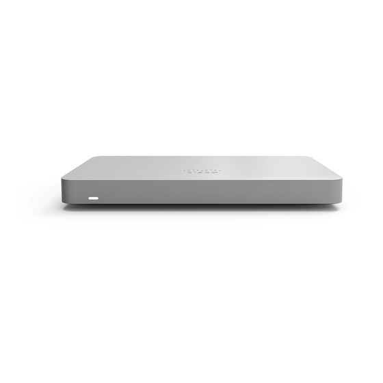
MX67/MX68 Overview
The Meraki MX67 and MX68 are enterprise security appliances
designed for distributed deployments that require remote administration.
It is ideal for network administrators who demand both ease of
deployment and a state-of-the-art feature set. A full overview of the
appliances' features can be found in the
Specifications.
Package Contents
In addition to the MX device, the following are provided:
MX67/MX68
Power Adapter (No Power Cable)
2x CAT5 Ethernet Cables
Wall Screws and Anchors
MX67C
Power Adapter (No Power Cable)
2x CAT5 Ethernet Cables
Wall Screws and Anchors
MX67 and MX68 Overview and
MX67W/MX68W
Power Adapter (No Power Cable)
2x CAT5 Ethernet Cables
Wall Screws and Anchors
2x WiFi Antennae
MX68CW
Power Adapter (No Power Cable)
2x CAT5 Ethernet Cables
Wall Screws and Anchors
1
Advertisement
Table of Contents

Related Manuals for Cisco Meraki MX67


Summary of Contents for Cisco Meraki MX67
-
Page 1: Package Contents
MX68 security appliance. Additional reference documents are available online at: www.meraki.com/library/products. MX67/MX68 Overview The Meraki MX67 and MX68 are enterprise security appliances designed for distributed deployments that require remote administration. It is ideal for network administrators who demand both ease of deployment and a state-of-the-art feature set. -
Page 2: Front Panels
MX67/MX68 MX67W/MX68W 2x Attached (Non-Removeable) Hybrid 2x LTE Antennae WiFi+LTE Antennae Front Panels MX67/67C/67W MX68/68W/68CW Status Indicator The MX67/MX68 series devices uses an LED to inform the user of the device's status. LED patterns and their meanings are described below. LED Status Meaning Power is applied but the appliance is not connected to... -
Page 3: Back Panels
Flashing White Firmware upgrade in progress Solid White Fully operational Back Panels MX67 MX67C... - Page 4 MX67W...
- Page 5 MX67/MX67W/MX67C Back Panel Functions Additional functions on the back panel are described below, from left to right. Active, supported SIM cards can be inserted into this SIM Card Slot (MX67C) slot to enable cellular capabilities. USB 3.0 for external 3G/4G wireless modems. Traffic USB port status is indicated by the USB LED.
- Page 6 A steady green LED indicates bidirectional connectivity, and flashing green indicates traffic. Power input Designed for use only with the unit’s power supply. Insert a paper clip if a reset is required. Press for 1 second to delete a downloaded configuration Reset button and reboot.
- Page 7 MX68CW MX68/MX68W/MX68CW Back Panel Functions Additional functions on the back panel are described below, from left to right. WAN / Internet ports These two ports provide connectivity to the WAN. These 8 ports provide connectivity to computers, printers, access points, or Ethernet switches. LAN ports A steady green LED indicates bidirectional connectivity, and flashing green indicates traffic.
-
Page 8: Side Panels
Each port outputs up to 30W of PoE power. A steady green LED indicates bidirectional connectivity, and flashing green indicates traffic. Power input Designed for use only with the unit’s power supply. Insert a paper clip if a reset is required. Press for 1 second to delete a downloaded configuration Reset button and reboot. - Page 9 MX68CW...
-
Page 10: Bottom Panel
MX68/MX68W/MX68CW Side Panel Functions Additional functions on the side panel are described below, from left to right. Active, supported SIM cards can be inserted into this SIM Card Slot (MX68CW) slot to enable cellular capabilities. USB 2.0 for 3G/4G wireless cards. Traffic status is USB port indicated by the USB LED. -
Page 11: Connecting To Wan
Mounting Hardware The supplied wall screws and anchors allow you to mount the appliance on a drywall surface, either vertically or horizontally. The distance between the holes you drill should be 5-1/8 inches (13 cm). • For mounting on drywall, use a ¼-in drill bit, then insert the plastic and screw assemblies. •... -
Page 12: Setting Up Cellular Failover
Setting up Cellular Failover The MX67C and MX68CW have an embedded LTE module for cellular failover connections. The following section will walk through first-time set-up of an MX with an internet connection as a primary connection and cellular as failover. Note that the IMEI cannot yet be found on the Meraki dashboard, only on the physical label of the device. -
Page 13: Additional Settings
Additional Settings Please note that all these settings below are accessible only via the local management console. Setting VLANs If your WAN uplink is on a trunk port, choose VLAN tagging > Use VLAN tagging and enter the appropriate value for VLAN ID for your network.