Advertisement
ZA des Petits Champs 26120 Montélier France
tel +33 (0)4 75 59 91 91 - www.coval.com
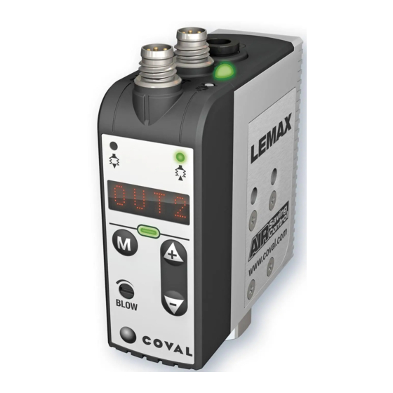
LEMAX
modules
1
%V
Vmax=85%
L2=75%
L1=65%
A
1
2
0
c
Air Saving Control
0
B
%V
Vmax=85%
L2=75%
L1=65%
Air Saving Control (ASC)
c
0
CYCLE 1
4.5/7 bar
P=4.5/7 bar
h2=10%
3.5 bar
3
t
"ASC"
t
no ASC
"ASC alarm"
CYCLE 2
CYCLE 3
LEMAX
integrated compact
vacuum pumps
This document is intended for users of LEMAX vacuum pumps in the
following versions:
- LEMAX90X -- S
- LEMAX90X -- V
I - WORKING PROCEDURE
The LEMAX vacuum pumps operate with "ASC": Air Saving Control.
Once vacuum is established, no more air consumption to hold the
product. The resulting energy saving is a key progress. Here is how
it is obtained.
A- The "Air Saving Control" automatic cycle
Example with a LEMAX -- X -- S module; On this module, the solenoid
valve ➋ is normally closed (NC).
The A diagram presents the 3 steps of the cycle:
1- Product gripping
Pressure regulator* ➊ supplies 3.5 bar to the "vacuum" solenoid
valve ➋. Vacuum signal
feeds venturi ➌. The generated vacuum grips the product. At 65%
vac., vacuum sensor ➏ generates the "product gripped"
that authorizes next step.
* The pressure regulator ➊ is included on standalone modules only.
2- Operations on vacuum gripped product
The operations on the product (transfer, machining...) will start.
When vacuum reaches threshold L2 (75%), the pressure supply
to the venturi is automatically stopped by solenoid valve ➋ no
more consumption. The product remains gripped by vacuum V that
is preserved, due to the closing of poppet ➎. Micro-leaks may lead
to the decrease in vacuum level. Each time it goes below L2-h2
(65%), the vacuum level is regenerated to L2 (75%) thanks to a
brief pressure supply to the venturi.
3- Product release
At the end of operations, release is ordered. "Blow-off" solenoid
valve ➑, piloted by blow-off signal
closes isolation valve ➓ and, through flow regulator ➒, blows off
the product for a quick release.
B- "Air Saving Control" cycle self-adaptation
The B diagram shows how the module adapts the cycle to fit to the
production realities: leaks due to products, to vacuum pads...
- Here, cycle 1 deals with an air tight product under the influence of
"ASC", resulting in optimum energy savings.
- At cycle 2 however, the porous product generates leaks that
provoke repeated intermittent vacuum regeneration. The anomaly is
automatically detected, and the cycle goes on but without "ASC. A
"ASC missing" signal is then emitted and displayed, and production
goes on.
ASC
- Cycle 3 illustrates the automatic return to the "ASC" cycle as
soon as leaks are eliminated: air tight products, vacuum circuit
maintenance...
The LEMAX module thus provides the maximum energy saving,
t
without any limitations to the performance and functioning of the
overall production system.
- 1 -
ENG
LEMAX
modules
Kompakte integrierte
Operating instruction
Vakuumpumpen
V4.0.1 software
Diese Dokument richtet sich an Nutzer der LEMAX Vakuumpumpen,
folgender Versionen:
- LEMAX90X -- SC14
- LEMAX90X -- S
- LEMAX90X -- W
- LEMAX90X -- V
I - BETRIEB
Die LEMAX-Vakuumpumpen funktionieren in „ASC": Air Saving Control.
Sobald das Vakuum hergestellt ist, verbraucht das Modul nicht weiter, um
das Vakuum aufrecht zu erhalten. Die derart erzielte Energieeinsparung
ist ein wesentlicher Fortschritt. Und so wird sie erzielt.
A- Der automatische Air Saving Control-Zyklus
Beispiel mit einem Modul LEMAX -- X -- S ; bei diesem Modul ist das
Elektromagnetventil ➋ normal geschlossen (NC).
Das Nomogramm A zeigt die 3 Schritte des Zyklus.
1- Werkstückaufnahme
Der Druckregler* ➊ versorgt das „Vakuum"-Magnetventil ➋. Das
starts the cycle by piloting valve ➋ that
Signal
von ➋, das das Venturi ➌ versorgt. Das dabei erzeugte Vakuum erfasst
r
signal
das Werkstück. Bei 65 % Vakuum erzeugt der Vakuumschalter ➏ das
r
Signal
„Werkstückaufnahme", das den nächsten Schritt erlaubt.
* Der Druckregler ➊ ist nur für die autonomen Module verfügbar.
2- Vorgänge an den vom Vakuum gehaltenen Werkstücken
Die Vorgänge an dem Werkstück (Transfer, Bearbeitung,...) finden
jetzt statt. Wenn das Vakuum den Schaltwert L2 (75%) erreicht, wird
die Versorgung der Venturidüse vom Magnetventil ➋ unterbrochen.
Der Druckluftverbrauch sinkt auf null. Das Werkstück wird weiterhin,
durch das Schließen der Klappe ➎, vom Vakuum V gehalten. Das
Vakuumniveau wird hierdurch aufrechterhalten. Mikroleckagen
können das Niveau des Vakuums langsam absinken lassen.
Immer, wenn das Vakuum auf L2-h2 (65%) sinkt, wird eine kurze
Vakuumerzeugung ausgelöst, um auf L2 (75 %) zurückzukehren.
3- Werkstückablegen
b
, generates an air jet that
Am Ende des Vorgangs wird das Ablegen angesteuert. Das
Magnetventil „Abblasen" ➑, das vom Signal
gesteuert wird, erzeugt einen Luftstrahl, der das Absperrventil ➓
schließt und bläst das Werkstück für ein schnelles Ablegen über die
Durchflusseinstellung ➒.
B- Automatische Anpassung des Air Saving Control-Zyklus
Das Nomogramm B zeigt, wie das Modul den Zyklus in Abhängigkeit
von den Produktionsgegebenheiten anpasst: Lecks auf Grund der
Werkstücke, der Saugnäpfe,...
- Hier verarbeitet der Zyklus 1 ein dichtes Werkstück und läuft in
„ASC" mit optimaler Energieeinsparung ab.
- Im Zyklus 2 hingegen, kommt ein poröses Werkstück an, dessen Lecks
aufeinander folgende „schlagende" Verbesserungen des Vakuums
auslösen. Diese Anomalie wird automatisch erkannt und der Betrieb
wird fortgesetzt, allerdings ohne „ASC". Ein Signal „Ohne ASC" wird
ausgegeben und angezeigt, die Produktion wird fortgesetzt.
- Der 3. Zyklus veranschaulicht die automatische Rückkehr zum
„ASC"-Betrieb, sobald die Lecks eliminiert sind: das Werkstück ist
dicht, der Vakuumkreislauf wird aufrecht erhalten, ...
Das LEMAX-Modul stellt daher die maximale Energieeinsparung sicher,
ohne irgendwelche Zwänge aufzuerlegen und ohne den Betrieb jemals
zu unterbrechen.
D
modules
Bedienungsanleitung
V4.0.1 Software
- LEMAX90X -- SC14
- LEMAX90X -- W
zum Steuern des Vakuums startet den Zyklus unter Steuern
b
der Abblassteuerung
Advertisement
Table of Contents


Need help?
Do you have a question about the lemax Series and is the answer not in the manual?
Questions and answers