Table of Contents
Advertisement
Quick Links
Advertisement
Table of Contents

Subscribe to Our Youtube Channel
Related Manuals for TECH L-6


Summary of Contents for TECH L-6
- Page 1 L-6 User’s manual User’s manual...
-
Page 2: Safety
TECH Safety Before using the device for the first time the user should read the following regulations carefully. Not obeying the rules included in this manual may lead to personal injuries or controller damage. The user’s manual should be stored in a safe place for further reference. -
Page 3: Description Of The Device
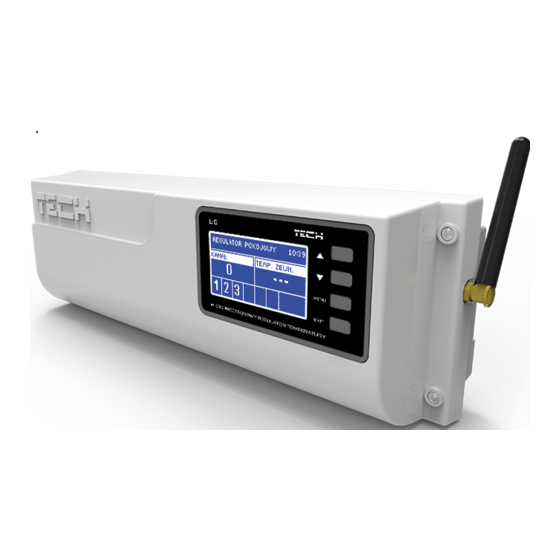
L-6 User’s manual Description of the device L-6 external controller is intended for both wired and wireless control of the valves. It allows the user to limit considerably the power consumption due to precise control of the room temperature. Thanks to advanced software, the device offers a wide range of functions: ... -
Page 4: Controller Installation
Risk of fatal electric shock from touching live connections. Before working on the controller switch off the power supply and prevent it from being switched on again. L-6 regulator may be installed as a free-standing device or as a panel mountable on a wall. - Page 5 L-6 User’s manual...
-
Page 6: Wireless Communication
TECH Wireless communication L-6 controller enables wireless communication with the following devices: Function Configuration - the room regulator needs ST-290v4 Sending information to be assigned to a ST-292v4 about selected area in the room two-state sufficient/insufficient regulator menu room temperature in a given... -
Page 7: First Start-Up
The user should check if the selected communication channel in the room regulators is the same as in L-6. ‘0’ is the default channel in all devices. If there is a conflict with other devices using radio communication, the user needs to select a different channel. -
Page 8: How To Use The Controller
How to use the controller V.a) Principle of operation L-6 controls the CH pump switching it on when the temperature in any of the six zones or the built-in valve is too low. The controller receives temperature information from the subordinate room regulators assigned to particular zones. -
Page 9: V.b) Main Screen View And Description
L-6 User’s manual V.b) Main screen view and description The user operates the controller using buttons located next to the display. 1. Information about active master room regulator (ST-285) 2. Current time 3. Buttons used to navigate 4. Current communication channel 5. -
Page 10: V.c.1) Block Diagram - Main Menu
TECH V.c.1) Block diagram – Main menu Main valve Pump Manual mode Voltage-free contact Valve 1-6 Channel 0 Channel; range: 0÷20 Valve status Pre-set valve temperature Opening time Main valve Valve type Weather-based control Factory settings External sensor Standard Wireless... -
Page 11: V.c.3) Channel
The user needs to select the same channel in all devices communicating with the L-6 controller. The range of channels is 0-20. ‘0’ is the default channel in the devices cooperating with L-6. The channel must be changed only if there conflict with other... -
Page 12: V.c.5) External Sensor
TECH selected when the valve is connected to the underfloor heating system, the fragile installation may be damaged. Weather-based control For the function of weather control to be active, the external sensor mustn't be exposed to sunlight or influenced by the weather conditions. After it is installed... -
Page 13: V.c.6) Pump
WARNING If a wireless external sensor is used, the user needs to check if the same communication channel is selected in L-6 controller. ‘0’ is the default channel in the external sensor. Channel change in the external sensor: Press and hold the channel change button in order to change the communication channel. -
Page 14: V.c.10) Display Contrast
Registration procedure: 1. Install the thermostatic actuator on the radiator. 2. Go to Registration in the Fitter’s menu of L-6 controller. 3. Choose the zone number in which the actuator will be registered and select Registration. -
Page 15: Internet Module
L-6 User’s manual view the status of an additional contact (ON/OFF) Regulator TECH option needs to be selected in order for the communication between L-6 and the room regulator to be active. 3) Internet module L-6 controller may cooperate with the Internet module allowing the user to view and change some of the parameters via the Internet. -
Page 16: Protections And Alarms
TECH VII. Protections and alarms In order to ensure safe and failure-free operation, the regulator has been equipped with a range of safeguards. In case of alarm, a sound signal is activated and the display shows an appropriate message. Automatic sensor control... -
Page 17: Table Of Contents
L-6 User’s manual Table of contents Safety ......................2 Description of the device ................3 III. Controller installation ................... 4 Wireless communication ................6 First start-up ....................7 How to use the controller ................8 V.a) Principle of operation .................. 8 V.b) Main screen view and description .............. - Page 18 TECH We are committed to protecting the environment. Manufacturing electronic devices imposes an obligation of providing for environmentally safe disposal of used electronic components and devices. Hence, we have been entered into a register kept by the Inspection For Environmental Protection. The crossed-out bin symbol on a product means that the product may not be disposed of to household waste containers.
- Page 19 L-6 User’s manual EU Declaration of conformity Hereby, we declare under our sole responsibility that L-6 manufactured by TECH, headquartered in Wieprz Biała Droga 31, 34-122 Wieprz, is compliant with: Directive 1999/5/EC of the European Parliament and of the Council of 9 March 1999 on radio...
- Page 20 TECH...
Need help?
Do you have a question about the L-6 and is the answer not in the manual?
Questions and answers