Table of Contents
Advertisement
Advertisement
Table of Contents

Related Manuals for GST I-9105R


Summary of Contents for GST I-9105R
-
Page 2: Table Of Contents
I-9105R Intelligent Reflective Beam Detector Installation and Operation Manual The Intelligent Solution CONTENTS Overview ..................1 Features..................1 Technical Specifications ..............2 Structure and Operation Principle ..........4 Mounting and Wiring ..............6 Ambient Conditions for Installation ..........6 Mounting Height and Position............7 Mounting..................10 Wiring ..................13 Commission ................14... -
Page 3: I Overview
Installation and Operation Manual The Intelligent Solution Overview I-9105R Intelligent Reflective Beam detector (the detector) is an addressable reflective infrared beam smoke detector that has two signal output ways: loop output and contact output. When the detector is connected with GST fire alarm control panel directly, state information will be transmitted through loop between the detector and the control panel. -
Page 4: Technical Specifications
I-9105R Intelligent Reflective Beam Detector Installation and Operation Manual The Intelligent Solution Built-in microprocessor enables intelligent judgment about fire alarm and fault. The detector can calibrate automatically, which ensures a single person complete adjustment in short time. It’s also convenient to operate. - Page 5 Fire output contact is closed. The fire signal can be transmitted to the control panel through loop and has to be cleared by the control panel. Power on the detector again to clear the fire signal if GST control panel is not connected.
-
Page 6: Structure And Operation Principle
I-9105R Intelligent Reflective Beam Detector Installation and Operation Manual The Intelligent Solution 11. Length of Optical Pathway: 8m~100m 12. Ingress Protection Rating: It is IP20 in ordinary environment; it is IP66 through glue-seal treatment in special environment. 13. Dimensions: Length: 206mm Width: 95mm Depth: 95mm 14. - Page 7 LED. And fire output contact is closed. If connected with GST control panel, the fire signal will be passed to the panel through loop.
-
Page 8: Mounting And Wiring
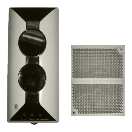
I-9105R Intelligent Reflective Beam Detector Installation and Operation Manual The Intelligent Solution Detector Body Reflector Smoke Infrared Beam Mounting Bracket Fig. 3 Mounting and Wiring Ambient Conditions for Installation The detector works on light obscuration principle. Avoid any fixed or moving obscuration in its optical pathway when installing. -
Page 9: Mounting Height And Position
I-9105R Intelligent Reflective Beam Detector Installation and Operation Manual The Intelligent Solution It is clean normally, but can be dusty in some special cases. Temperature is high. Note: Temperature at top part of a workshop with transparent roof may be over 50℃ when there is sunshine. - Page 10 I-9105R Intelligent Reflective Beam Detector Installation and Operation Manual The Intelligent Solution When space height is between 5m and 8m, the detector and reflector should be mounted on the two facing walls 0.5m to 1m from the ceiling, as shown in Fig. 5.
- Page 11 I-9105R Intelligent Reflective Beam Detector Installation and Operation Manual The Intelligent Solution Reflector Reflector Detector Detector Fig. 6 For gable structure with space height about 8m, the detector and reflector should be mounted on the two facing walls 1.5m from the gabled girder, as shown in Fig.
-
Page 12: Mounting
I-9105R Intelligent Reflective Beam Detector Installation and Operation Manual The Intelligent Solution cannot be mounted northward, then place the detector on the west wall. For applications where sunlight can reach the detector after reflected, please consider mounting a sunshade over the detector’s optical pathway or contact our field application engineer... - Page 13 I-9105R Intelligent Reflective Beam Detector Installation and Operation Manual The Intelligent Solution The detector can be surface-mounted in two ways: with conduit embedded surface-mounted. (1)Embedding conduit a. Remove the detector’s top cover. b. Align the base of the detector over the back box and mark the positions of mounting holes on the wall.
- Page 14 I-9105R Intelligent Reflective Beam Detector Installation and Operation Manual The Intelligent Solution b. Drill the holes on marked positions, and push ∅6 plastic expansion bolts in. c. Fix the mounting bracket on the wall with four ∅6 plastic expansion bolts and flat washers.
-
Page 15: Wiring
I-9105R Intelligent Reflective Beam Detector Installation and Operation Manual The Intelligent Solution are needed, place them seamlessly as shown in Fig. 11b. Unit: mm Fig. 11a Fig. 11b 4. Wiring Connect 24VDC power wire (without polarity) to terminal D1 and D2 of the detector in field. -
Page 16: Commission
I-9105R Intelligent Reflective Beam Detector Installation and Operation Manual The Intelligent Solution Fig. 12 Wiring: 1.5mm above fire cable connecting with D1 and D2. 1.0mm above twisted pair connecting with Z1, Z2, K11, K12, K21, and K22. Cross section for earth cable should not be less than 1.0 mm Note: If the detector is mounted in special environment where there are slight dust or where it’s damp, seal the three positions... - Page 17 I-9105R Intelligent Reflective Beam Detector Installation and Operation Manual The Intelligent Solution step d). If green LED illuminates continuously, it means the received light is quite strong, you can go straight to step d). Note: Observe the detector’s optical pathway carefully to ensure that the received light signal is reflected by the reflector rather than by obscurations like wall, ceiling, or pillar.
-
Page 18: Cautions
I-9105R Intelligent Reflective Beam Detector Installation and Operation Manual The Intelligent Solution turned off. Failed Detector During testing, repair failing detectors according to directions in Section IX Troubleshooting and X Maintenance, and test again, if they fail again, return them to factory for repair. -
Page 19: Setting Address Code
I-9105R Intelligent Reflective Beam Detector Installation and Operation Manual The Intelligent Solution Press Up, the screen shows sensitivity level and device type in sequence. Press Down, the screen shows above contents in opposite Setting Address Code The detector offers address code programming for field application. -
Page 20: Other Functions
I-9105R Intelligent Reflective Beam Detector Installation and Operation Manual The Intelligent Solution Enter I C mode of the programmer, and the screen shows “0”. Input unlock password, press Clear, and open the lock. Press Function and then figure “4”, the screen shows “-”. -
Page 21: Troubleshooting
I-9105R Intelligent Reflective Beam Detector Installation and Operation Manual The Intelligent Solution IX Troubleshooting Common problems and repair methods are as shown in Table 1. Table 1 Problems Reasons Repair Methods Working LEDs a) 24V power off If the problems are not lit after b) Working LEDs damaged. -
Page 22: Maintenance
I-9105R Intelligent Reflective Beam Detector Installation and Operation Manual The Intelligent Solution Fire signal a) There are obscuration on the optical If the problems are cannot be pathway between the detector and mentioned in a), b), cleared the reflector. commission once again. -
Page 23: Accessories
I-9105R Intelligent Reflective Beam Detector Installation and Operation Manual The Intelligent Solution XI Accessories Accessories provided with the detector are as follows: Four plastic expansion bolts. One bracket. Two M4×10 cross recessed pan head screws. One IR Light Filter. Six ∅4 flat washers. -
Page 24: Appendix 1 Warnings
I-9105R Intelligent Reflective Beam Detector Installation and Operation Manual The Intelligent Solution Appendix 1 Warnings Limitations of Smoke Detector The smoke detector is designed for triggering and initiating emergency fire equipments, but it only functions when matching with other equipments. Installation of this smoke detector must conform to electrical codes and standards in your country. -
Page 25: Appendix 2 Warranty
Appendix 2 Warranty GST warrants that the product will be free from defects in design, materials and workmanship during the warranty period. This warranty shall not apply to any product that is found to have been improperly installed or used in any way not in accordance with the instructions supplied with the product. - Page 26 GST China Gulf Security Technology Co., Ltd. No. 80, Changjiang East Road, QETDZ, Qinhuangdao, Hebei, P. R. China 066004 Tel: +86 (0) 335 8502528 Fax: +86 (0) 335 8508942 Email: sales@gst.com.cn www.gst.com.cn GST UK Global System Technology PLC Lion Court, Staunton Harold Hall, Melbourne Road, Ashby de la Zouch,...
Need help?
Do you have a question about the I-9105R and is the answer not in the manual?
Questions and answers