Table of Contents
Advertisement
Quick Links
Advertisement
Table of Contents

Related Manuals for GST C-9105R


Summary of Contents for GST C-9105R
- Page 1 E-MAIL: hombi@hombi.ru HTTP://GSTRU.RU HTTP://WWW.HOMBI.RU...
-
Page 2: Table Of Contents
C-9105R Conventional Reflective Beam Detector Installation and Operation Manual The Intelligent Solution CONTENTS Overview .................1 Features ..................1 Technical Specification............2 Structure and Operation Principle ........4 Mounting and Wiring..............6 Ambient Conditions for Installation ........6 Mounting Height and Position..........7 Mounting................10 Wiring .................14 Commission................15 Cautions ................17... -
Page 3: I Overview
Installation and Operation Manual The Intelligent Solution Overview C-9105R Conventional Reflective Beam Detector (hereinafter called the detector) is a non-addressable reflective infrared beam smoke detector, which must be used together with a reflector. The number of reflector(s) to be used (one or four) depends on the distance from the detector. -
Page 4: Technical Specification
C-9105R Conventional Reflective Beam Detector Installation and Operation Manual The Intelligent Solution convenient to operate. (5) Self-diagnosis function can monitor the inner fault. (6) Automatic compensation for factors weakening received signals, such as dust contamination, positional excursion and ageing transmitter. - Page 5 C-9105R Conventional Reflective Beam Detector Installation and Operation Manual The Intelligent Solution certain way. Refer to details in Section VI Commission. Normal monitoring state: Red LED flashes periodically. Fire: Red LED constantly illuminates,. Fire alarm should be cleared through powering up again.
-
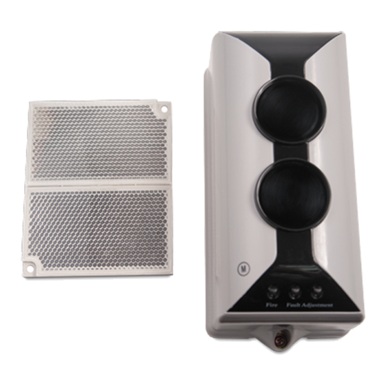
Page 6: Structure And Operation Principle
C-9105R Conventional Reflective Beam Detector Installation and Operation Manual The Intelligent Solution Spacing for embedding: 158mm Spacing for surface mounting: 79mm×96mm IV Structure and Operation Principle (1) Appearance of the detector is shown in Fig. 1. Receiving Window Emitting Window... - Page 7 C-9105R Conventional Reflective Beam Detector Installation and Operation Manual The Intelligent Solution (3) Operation Principle The detector and reflector are placed oppositely. The detector includes emitting part and receiving part. Infrared beam of certain intensity sent out from the emitting part is reflected by the right-angle prisms of the reflector, and then received by the receiving part of the detector.
-
Page 8: Mounting And Wiring
C-9105R Conventional Reflective Beam Detector Installation and Operation Manual The Intelligent Solution Mounting and Wiring Ambient Conditions for Installation The detector works on light obscuration principle. Avoid any fixed or moving obscuration in its optical pathway when installing. The wall for mounting either the detector or the reflector should be firm and smooth. -
Page 9: Mounting Height And Position
C-9105R Conventional Reflective Beam Detector Installation and Operation Manual The Intelligent Solution There is strong magnetic field. Mounting Height and Position The mounting height of the detector and reflector should be most accessible smoke into beam zone. following recommendations are for reference. - Page 10 C-9105R Conventional Reflective Beam Detector Installation and Operation Manual The Intelligent Solution Reflector Detector Fig. 5 When space height is more than 8m, the roof is normally gabled without ceiling, the detector and reflector should be mounted on the two facing walls about 8m from the floor,...
- Page 11 C-9105R Conventional Reflective Beam Detector Installation and Operation Manual The Intelligent Solution Reflector Reflector Detector Detector Fig. 6 For gable structure with space height about 8m, the detector and reflector should be mounted on the two facing walls 1.5m from the gabled girder, refer to Fig. 7.
-
Page 12: Mounting
C-9105R Conventional Reflective Beam Detector Installation and Operation Manual The Intelligent Solution Reflector Reflector Reflector Detecor Detector Detector Fig. 7 If the surroundings are glass or transparent plastic, please place the detector on the south wall in a building. If the detector cannot be mounted northward, then place the detector on the west wall. - Page 13 C-9105R Conventional Reflective Beam Detector Installation and Operation Manual The Intelligent Solution at two levels of length. When mounting distance between the detector and the reflector is not less than 40m (but no more than100m), the detector type should be set at “54” (factory default).
- Page 14 C-9105R Conventional Reflective Beam Detector Installation and Operation Manual The Intelligent Solution a. Remove the detector’s top cover. b. Align the base of the detector over the electrical box and mark the positions of mounting holes on the wall. c. Drill two holes at the marked positions, and push two ∅6 plastic expansion bolts in.
- Page 15 C-9105R Conventional Reflective Beam Detector Installation and Operation Manual The Intelligent Solution expansion bolts in. c. Fix the mounting bracket on the wall with four ∅6 plastic expansion bolts and flat washers. d. Remove the detector’s top cover; thread the wires...
-
Page 16: Wiring
C-9105R Conventional Reflective Beam Detector Installation and Operation Manual The Intelligent Solution more than 8m(less than or equal to 40m), one reflector is enough. When the distance is more than 40m (less than or equal to 100m), four reflectors are needed. Two ∅6 plastic expansion bolts are needed to fix single reflector. -
Page 17: Commission
C-9105R Conventional Reflective Beam Detector Installation and Operation Manual The Intelligent Solution Fig. 12 Wiring: Twisted pair with cross section not less than 1.0mm signal wires connecting with K11, K12, K21 and K22. 1.5mm above fire cable for terminals D1 and D2. - Page 18 C-9105R Conventional Reflective Beam Detector Installation and Operation Manual The Intelligent Solution detector to align the light beam until Green LED is lit continuously, showing that the light received by the detector is strong. Then stop regulating and enter step 4). If Green LED illuminates continuously, it means the received light is quite strong, you can go straight to step 4).
-
Page 19: Cautions
C-9105R Conventional Reflective Beam Detector Installation and Operation Manual The Intelligent Solution Light Filter (please use the part for fire alarm test), the detector should alarm fire in 30s and Red LED should turn on. Fire volt-free contact is closed. Removing the filter, the detector should enter normal monitoring state directly without alarming fire or fault. -
Page 20: Operation
C-9105R Conventional Reflective Beam Detector Installation and Operation Manual The Intelligent Solution VIII Operation Device type and sensitivity level of the detector can be set with P-9910B Hand Held Programmer. Open the detector’s top cover, C cable of hand held programmer ( PS/2 cable) with XT3 connect I of the detector. -
Page 21: Setting Device Type
C-9105R Conventional Reflective Beam Detector Installation and Operation Manual The Intelligent Solution programming. The screen will show a “P” if programming is successful, otherwise it will show an “E”. Press Clear key, the screen shows a “0”, and you can go on with further operations. -
Page 22: Troubleshooting
C-9105R Conventional Reflective Beam Detector Installation and Operation Manual The Intelligent Solution and reflector surface reaches a certain level and the light compensation reaches the limit for the detector to work normally. 2) Self-diagnosis on Optical Signal The detector has functions of checking emitting, receiving and amplifying circuit. -
Page 23: Maintenance
C-9105R Conventional Reflective Beam Detector Installation and Operation Manual The Intelligent Solution Reports fire alarm Commission once more. after a period of The detector has deviated operation, alarms due to external vibration. detector fault after restart a) There are obstruction on... -
Page 24: Accessories
C-9105R Conventional Reflective Beam Detector Installation and Operation Manual The Intelligent Solution XI Accessories Accessories provided with the detector are as follows. Four ∅6 plastic expansion bolts. One bracket. One IR Light Filter. Two M4×10 cross recessed pan head screws. -
Page 25: Appendix 1 Warnings
C-9105R Conventional Reflective Beam Detector Installation and Operation Manual The Intelligent Solution Appendix 1 Warnings Limitations of Smoke Detector The smoke detector is designed for triggering and initiating emergency fire equipments, but it only functions when matching with other equipments. Installation of this smoke detector must conform to electrical codes and standards in your country. - Page 26 C-9105R Conventional Reflective Beam Detector Installation and Operation Manual The Intelligent Solution relative nation codes and laws. Take specific maintenance measures on the basis of different environments. The smoke detector contains electronic parts. Even though it’s made to last for a long period of time, any of these parts could fail at any time.
-
Page 27: Appendix 2 Warranty
C-9105R Conventional Reflective Beam Detector Installation and Operation Manual The Intelligent Solution Appendix 2 Warranty Our company warrants that the detector will be free from defects in design, materials and workmanship. The warranty is valid for a period of 2 years from time of dispatch. This warranty shall not apply... - Page 28 GST China Gulf Security Technology Co., Ltd. No. 80, Changjiang East Road, QETDZ, Qinhuangdao, Hebei, P. R. China 066004 Tel: +86 (0) 335 8502528 Fax: +86 (0) 335 8508942 Email: sales@gst.com.cn www.gst.com.cn GST UK Global System Technology PLC Lion Court, Staunton Harold Hall,...
Need help?
Do you have a question about the C-9105R and is the answer not in the manual?
Questions and answers