Alpha-InnoTec LUXTRONIK Operating Instructions Manual
Heating - and operating instructions heat pump control
Hide thumbs
Also See for LUXTRONIK:
- Operating manual (52 pages) ,
- Instruction manual (48 pages) ,
- Operating instructions manual (44 pages)
Table of Contents
Advertisement
Quick Links
Operating Instruc tions
UK
Controller part 1 (Customer & Qualified technican)
Program area "Info + Einstellung"
Program area "Heatung"
Program area "Domestic hot water"
Program area "Cooling"
Program area "Parallel connection"
Program area "Service"
LUXTRONIK
Heating - and
Heat Pump Control
83055200aUK – Translation of the original instruction manual – We reserve the right to make technical changes..
Advertisement
Table of Contents

Related Manuals for Alpha-InnoTec LUXTRONIK


Summary of Contents for Alpha-InnoTec LUXTRONIK
- Page 1 Program area “Heatung“ Program area “Domestic hot water“ Program area “Cooling“ Program area “Parallel connection“ Program area “Service“ LUXTRONIK Heating - and Heat Pump Control 83055200aUK – Translation of the original instruction manual – We reserve the right to make technical changes..
-
Page 2: Please Read First
Please read first Symbols This operating manual provides important information on the Information for operators. handling of the unit. It is an integral part of the product and must be stored so that it is accessible in the immediate vicinity of the Information or instructions for qualified technicians unit. -
Page 3: Table Of Contents
Contents INFORMATION FOR USERS, QUALIFIED TECHNICIANS AND PROGRAM AREA “INFORMATION AND QUICK SETTING” AUTHORISED SERVICE PERSONNEL SELECT PROGRAM AREA ..................13 PLEASE READ FIRST ....................2 THE MENU “QUICK SETTING: HEATING” ............13 SYMBOLS ........................2 Setting the heating mode of operation .......... - Page 4 PROGRAM AREA “HOT WATER“ PROGRAM AREA “SERVICE“ Calling up short programs ..............36 SELECT PROGRAM AREA ..................25 Determining priorities ................36 SETTING THE MODE OF OPERATION “DOMESTIC HOT WATER PREPARATION” ............25 DATA LOGGER ......................36 SET THE DOMESTIC HOT WATER TEMPERATURE ......... 25 CONTROL PANEL ....................
-
Page 5: Functioning Of The Heating And Heat Pump Regulator
Functioning of the heating Safety and heat pump regulator The unit is operationally safe when used for the intended pur- pose. The construction and design of the unit conform to the The heating and heat pump regulator consists of an operating el- state of the art, all relevant DIN/VDE regulations and all relevant ement and an electronic control. -
Page 6: Care Of The Unit
Disposal ATTENTION Never shut off heating circle to the heat pump (frost pro- When decommissioning the unit, always comply with applicable tection). laws, directives and standards for the recovery, recycling and dis- posal of materials and components of cooling units. ATTENTION Use only accessories provided by or approved by the man- Part 2 of tne manual of the Heating- and Heatpump Con-... -
Page 7: The Control Unit
The control unit Some menus require the settings you have made to be saved. You can do so through activation and selection of . You can also cancel the settings you have made through activation and selection of If a menu has more entries than the screen can display, a scroll bar will appear on the left of the screen. -
Page 8: Error Messages
ERROR MESSAGES If a fault occurs in the system, a corresponding error message will appear in the screen. ATTENTION Before acknowledging a fault, make sure to read the chap- ters “Error Diagnosis / Error Messages” and “Acknowledging a Fault.. Part 2 of tne manual of the Heating- and Heatpump Con- trol, Overview (Appendix) “Error Diagnosis / Error Mes- sages”... -
Page 9: Determining Date And Time
DETERMINING DATE AND TIME ADJUSTING THE CONTRAST OF THE CONTROL ELEMENT DISPLAY Adjust the contrast of the control element display to your needs. Adjust the contrast by turning the “rotary pushbutton” MENU DISPLAY The menu structure is such that menu items that are irrelevant to the system or machine type will be hidden. -
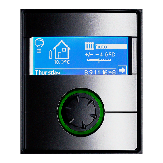
Page 10: Standard Screen
Standard screen SWITCH TO STANDARD SCREEN “DOMESTIC HOT WATER” The standardscreen (= standard-menu) is used for a fast informa- tion about the selected mode of operation. Additional you can set basic settings fast and convenient. STANDARD SCREEN “HEATING“ 1 Symbol for program area “Heating” The symbol used for the heating indicates that the ad- joining displays and setting options are only relevant to the heating. -
Page 11: The Navigation Screen
THE NAVIGATION SCREEN DISPLAY OF FURTHER PROGRAM AREAS The navigation screen provides an overview of the various pro- Depending on the type of heat pump connected, the navigation gram areas of the heating and heat pump regulator. screen can display the following program area symbols: BASIC DISPLAY Symbol for program area “Cooling”... - Page 12 NOTICE If you select and activate the symbol of a special program, you will be taken directly to the relevant special program. The displays described on the following pages allow / require you to make a selection. In general: – you can only select one option in circular fields: –...
-
Page 13: Program Area "Information And Quick Setting
SETTING THE HEATING MODE OF OPERATION Program area “Information and Quick Setting” SELECT PROGRAM AREA The current mode of operation is highlighted with : Auto Heating circle works according to programmed time pro- grams. Party Continuous heating boost. The settings for night mode are switched off straightaway for the duration of 24 hours or until another mode of operation is selected. -
Page 14: Setting The Hot Water Return Flow Temperature
SETTING THE HOT WATER RETURN FLOW TEMPERATURE NOTICE This menu performs the same function as the “Quickly changing the hot water return flow temperature” in the standard screen. Week (Mo – Su) Same times for all days of the week 5 + 2 (Mo –... -
Page 15: Different Switching Times During The Week And On Weekends
NOTICE NOTICE With a time period of 00:00 – 00:00 the heating is generally With a time period of 00:00 – 00:00 the heating is generally lowered. It only works in night mode. lowered. It only works in night mode. Scroll down the menu. -
Page 16: The Menu "Info + Setting Domestic Hot Water
THE MENU “INFO + SETTING DOMESTIC HOT WATER“ Sunday 1 Menu field “Current mode of operation” The displayed time programs apply for every day of the Possible displays: Auto week. The heating is raised within the time period indi- cated (= day mode). The heating is also lowered at the re- Party (=Continuous daytime operation) maining times (= night mode). -
Page 17: Setting The Domestic Hot Water Mode Of Operation
SETTING THE DOMESTIC HOT WATER MODE OF SETTING THE DOMESTIC HOT WATER OPERATION TEMPERATURE The current mode of operation is highlighted with Set the required domestic hot water temperature (= set- point value): 30 °C. Automatic Terminate input. This saves the required temperature. Domestic hot water preparation is stopped after the programmed program times. -
Page 18: Setting The Domestic Hot Water Off-Times
THE MENU “INFO + SETTING COMPLETE SYSTEM“ SETTING THE DOMESTIC HOT WATER OFF-TIMES You can only select and activate the “Off-times” – – if the “Automatic” mode of operation is active. 1 Menu field “current mode of operationt“ Possible displays: Auto Party (=Continuous daytime operation Holidays –... - Page 19 Party All areas of your system are automatically switched over to continuous day mode. After the party has finished, select and activate the “Complete system” menu, then select and activate the menu field “Automat- ic” in the “Mode of operation” menu: Automatik All areas of your system are switched over to the “Auto- matic”...
-
Page 20: Program Area "Heating
Program area “Heating“ NOTICE This menu allows you to carry out the fine setting of the heating curves. If temperature changes are saved, this is accepted auto-adaptively into the heating curves. SELECT PROGRAM AREA This means: On the basis of the changes in the menu “Temperature + -”, the program of the heating and heat pump regulator cal- culates the base and end point of the heating curves in re- lation to the external temperature and offsets it... -
Page 21: Setting The Heating Curves Of The Heating Circle
SETTING THE HEATING CURVES OF THE HEATING SELECT TABLE “HEATING CURVE END POINT CIRCLE Set the return flow temperature value in the table field “Heating curve end point”. NOTICE The heating curve end point always refers to an external temperature of -20 °C. If the heat pump is used in a climatic zone in which the external temperature value of -20 °C is not reached, you need to equalise the heating curve end NOTICE... -
Page 22: Determine The Heating Curve End Point
DETERMINE THE HEATING CURVE END POINT SELECT THE TABLE FIELD DIFFERENCE TEMPERATURE (LOWERED IN NIGHT MODE) Set return temperature value. Example diagram: Set return temperature value. A turn to the right results in a parallel offset of the heating curve by 0.5 °C upwards. A turn to the left results in a parallel offset of the heating curve by 0,5 °C downwards. -
Page 23: Setting The Heating Curves Of Mixing Circle 1
SETTING THE HEATING CURVES OF MIXING CIRCLE 1 NOTICE Menu access to the heating curves of mixing circle 1 is only possible if a mixer is installed in the system and mixing cir- cle 1 is defined as a discharge mixing circle in the system setting. -
Page 24: Fixed Temperature Heating Curves
FIXED TEMPERATURE HEATING CURVES X External temperature Y “Return temperature” Antifreeze Fixed temperature (here: + 35 °C) If the option “Fixed temperature” is switched on by the system setting, the screen changes to the menu “Heat- TIME PROGRAM HEATING ing curves” (which can take you to the menus “Fixed val- ue heating circle”... -
Page 25: Program Area "Hot Water
Program area “Hot water“ NOTICE If a domestic hot water temperature is set which cannot be attained, the heat pump will initially switch to “Error high SELECT PROGRAM AREA pressure”. This is followed by a self-resetting fault (If heat- ing is required, this will also be operated). After 2 hours have passed, the domestic hot water preparation starts again. -
Page 26: Hot Water Temperature With Reheating
Zieltemperatur K lower than the maximum flow temperature of your heat pump. Zielwert für die Warmwassertemperatur im Warmwas- serspeicher- Menüfeld aktivieren und gewünschte Tem- peratur einstellen. Einstellung speichern. HOT WATER TEMPERATURE WITH REHEATING Deckung WP Warmwassertemperatur, die zur letzten Warmwasserbe- If water heating with reheating is activated, if the required hot wa- reitung durch die Wärmepumpe erreicht wurde ter temperature cannot be reached with the heat pump, a sec-... -
Page 27: High-Speed Charge
NOTICE When programming, ensure that the time periods which you specify in the area “Time progs“ are o f f – t i m e s . The domestic hot water preparation is switched off in the time periods entered. HIGH-SPEED CHARGE If you require domestic hot water despite active off-time(s), you can select a domestic hot water preparation and then terminate it... -
Page 28: Circulation
CIRCULATION IMPULSE Under the time program item, you can decide how long the pump is to be switched on and off during the released time periods. NOTICE The menu field will only appear if this is correspondingly Example 1: defined in the program area “Service”. necessary setting: service water 2 = “CP“... -
Page 29: Program Area "Cooling
SELECT PROGRAM AREA Program area “Cooling“ ATTENTION Only select the program area “Cooling” if a cooling circle mixer is connected in conjunction with a brine/water heat pump or a LWD. ATTENTION If a cooling circle mixer is connected, it is imperative to se- Menu field “mode of operation“... -
Page 30: Setting The Cooling Temperature
SET PARAMETER SETTING THE COOLING TEMPERATURE AT-exceeded Menu line “Outside temperature-exceeded” AT-undershot Menu line “Outside temperature-undershot“ Set required time (in hours). Save settings. AT-Releasee Required Outdoor Temperature release NOTICE Set temperature mixing circle MK1 Cooling will not set in unless the temperature has risen Required Set temperature for Cooling above TOut rel. -
Page 31: Program Area "Parallel Connection
Program area “Parallel connection“ NOTICE Parallel operation is not possible unless all integrated heat pumps are fitted with the same number of compressors! NOTICE NOTICE Parallel operation is not possible with output controlled The el. sup. blockade must always be connected to the air/water heat pumps and with hydraulic module 2! master heat pump and the heat pump responsible for do- mestic hot water preparation! - Page 32 Example 2: 2 heat pumps used only for heating ZWE 1 Example 3: 2 heat pumps for heating mode, 1 heat pump is responsible for domestic water heating ZWE 1 ZWE 1/2 Domestic hot water temperature sensor ZWE 1 Second heat generator 1 External senso External return flow sensor Release signal electric suppl.
-
Page 33: Select Program Area
SELECT PROGRAM AREA SET OR CHANGE THE IP ADDRESS The program area “Parallel connection” must be set by authorised service personnel during commissioning. Example: Default IP setting for the heat pump Master: Menüfeld “Parallel Connection“ The heatpump is either defined as “Master“ or as “Slave“. Is the heatpumpe defined as “Master“... -
Page 34: External Return Flow Sensor
As soon as the search is finished the IP addresses of all heat NOTICE pumps integrated in the network are displayed: The first three number blocks of the IP addresses must always be identical (as in the illustrated example: 192.168.002). The fourth number block must always differ from heat pump to heat pump (in the illustrated example: 010 for heat pump master, 011 for heat pump slave 1)! The subnet mask, broadcast and gateway number must be... -
Page 35: Setting The Heating
SETTING THE HEATING Menu field “Switch Cycle“ means heating control time. This time defines at what in- terval the heating is supposed to switch to the next high- er / lower bivalent level (compressor switch-on/shut-off). This value should not be set to less than 10 minutes for 2 heat pumps. -
Page 36: Program Area "Service
Program area “Service“ CALLING UP SHORT PROGRAMS The short programs serve to make service work easier. Save settings. DATA LOGGER The controller is equipped with a data logger which records the data of the heat pump for a period of 48 hours (temperatures, in- puts/outputs). -
Page 37: Control Panel
CONTROL PANEL WEB SERVER The left socket at the bottom of the control element can be used to connect to a computer or a network, enabling the heating and heat pump regulator to be controlled remotely from there. This requires the laying of a screened network cable (category 6) through the unit during the electrical connection work. -
Page 38: Remote Maintenance
SWITCH ON THE REMOTE MAINTENANCE If the computer is connected via a router and, thus, the “DHC Server” of the heating and heat pump regulator is disabled, you FUNCTION will have to adjust the IP address as well as all other entries (sub- net mask, broadcast, gateway) shown on the screen of the heat- ing and heat pump regulator to the address areas of your router. -
Page 39: Check Connection
CHECK CONNECTION If connection problems arise, the following message will appear on the screen: NOTICE Checking the connection is essential at the time of initial adjustment. page 39, “Error causes with connection problems“ ERROR CAUSES WITH CONNECTION PROBLEMS If a connection with the remote maintenance server is not possi- Enter the serial number of the heat pump…... - Page 40 ait-deutschland GmbH Industriestrasse 3 D – 95359 Kasendorf E-mail: info@alpha-innotec.com www.alpha-innotec.com...
Need help?
Do you have a question about the LUXTRONIK and is the answer not in the manual?
Questions and answers