
Related Manuals for Alpha-InnoTec HMD 1/E


Summary of Contents for Alpha-InnoTec HMD 1/E
- Page 1 Accessories for Dual Air / Water Heat Pumps Outdoor installation Operating Manual Hydraulic Module HMD 1/E Hydraulic Module HMD 1/RE 83053600iUK...
-
Page 2: Table Of Contents
Table of contents About this operating manual 15 Faults ...... 3 .............. 18 Validity ............3 15.1 Unlock safety temperature limiter ... 18 Reference documents ....... 3 15.2 Manually unblock the circulating pumps . 19 Symbols and markings ......3 16 Dismantling and disposal ...... -
Page 3: About This Operating Manual
About this operating manual Symbol Meaning Safety-relevant information. This operating manual is part of the unit. Warning of physical injuries. Danger of fatal injury due to ► Before working on or with the unit, read the electric current. operating manual carefully and follow it for all DANGER Indicates imminent danger resulting activities at all times, especially the warnings and... -
Page 4: Contact
1.4 Contact The product may only be opened by qualified personnel. All procedural instructions in this operating manual is Addresses for purchasing accessories, for service solely directed at qualified, skilled personnel. cases or for answers to questions about the unit and this operating manual can be found on the internet and Only qualified, skilled personnel is able to carry out are kept up-to-date: the work on the device safety and correctly. -
Page 5: Residual Risks
2.4 Residual risks ● Negative effect on heat transfer, e.g. formation of coatings, deposits, and associated noises, e.g. boiling noises, flow noises Injuries caused by electric shock ► Note and follow the information in this operating Components in the unit are energised with life- manual for all work on and with the unit. threatening voltage. -
Page 6: Care
3.2 Care 4.1 Accessories Wipe down the outside of the unit only using a damp The following accessories are available for the unit cloth or cloth with mild cleaning product (washing-up through the manufacturer's local partner: liquid, neutral cleaning agent). Never use any harsh, ●... -
Page 7: Components Of The Unit
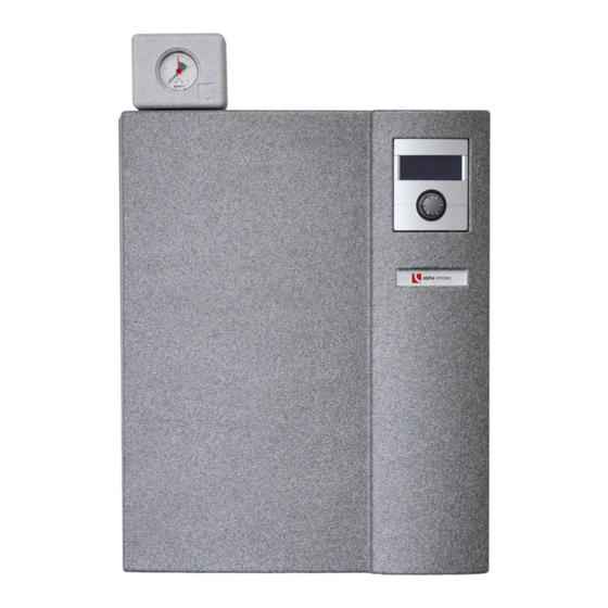
4.2 Components of the unit Different variants of the hydraulic module are available: HMD 1/E HMD 1/RE Shut-off ball valve with filling and drain tap Heating water outlet (supply) Enery-efficient circulating pump heating circuit Expansion vessel Volumetric flow meter Electric heating element Air separator Heating circuit safety module (insulated) Control panel 10 Comfort board (accessory) 11 Electrical switch box 12 Heating water inlet (supply) 13 Shut-off ball valve with drain tap and venting to be mounted at the installation location Subject to technical amendments without prior notice | 83053600iUK | ait-deutschland GmbH... -
Page 8: Storage, Transport, Installation
Nameplate 5.2.1 Transport with handcart A nameplate is attached to the outside of the unit at the factory. The nameplate contains the following information at the very top: ● Model, item number ● Serial number The nameplate also contains an overview of the most important technical data. -
Page 9: Installation
5.3 Installation Insert the plugs and hanger bolts supplied into the holes drilled. The plugs supplied are only suitable for use with Installation location the following types of walls: ● Concrete IMPORTANT ● Solid lightweight concrete blocks Install the unit inside buildings only. ●... -
Page 10: Install The Hydraulic Connections
Install the hydraulic Mount the unit to the wall. connections NOTE The safety valve that is integrated or included in delivery has a tolerance of plus / minus 10% for the set pressure. If local regulations, laws, standards or directives require a smaller tolerance range, the safety valve must be replaced on site with a safety valve that meets the requirements. -
Page 11: Heating Circuit
6.1 Heating circuit Lay the safety discharge of the safety valve into the drain via a funnel waste trap according to the relevant standards and guidelines. Safety module and shut-off ball valves It is essential that the safety discharge is connect- Take the safety module and the shut-off ball valves out of the accessory pack and fit them to the connections provided. -
Page 12: Electrical Installation
Electrical installation 6 Cable routing 7 Return flow sensor Connect the electrical cables 7.2 Electrical connection The electrical connection between the heat pump and IMPORTANT hydraulic module is made using the 3 pre-installed ca- Irreparable damage to the compressor due to bles on the heat pump. wrong rotating field (only applies to units with 400V The hydraulic module is connected electrically on site connection). - Page 13 Fasten the return sensor (①) to the heat-conduct- Push the shielding of the stripped bus cable back- ing pipe of the return line leading to the heat pump wards over the cable sheath. (②) using cable ties and thermal compound. Insert the end of the insulated cable with the shield into the shield terminal.
- Page 14 NOTE NOTE The control panel of the heating and heat pump The integrated electric heating element is controller can be connected to a computer connected at 6kW in the factory. At contactor or network using a suitable network cable, Q, it is possible to select 4kW = 2 phase enabling the heating and heat pump controller operation. Disconnect Q5/6 for this. Or 2kW to be controlled remotely from there.
-
Page 15: Control Panel
Control panel Flushing, filling and venting The control panel is pre-assembled at the factory. 9.1 Heating water quality If the control panel needs to be removed for any rea- son: NOTE Take off the front hood. For detailed information refer, among other Disconnect or unplug all connections at the bottom. things, to the VDI Guidelines 2035 “Vermei- dung von Schäden in Warmwasserheizanla- Lift off the control panel. - Page 16 Flush the domestic hot water charging circuit for NOTE approx. 1 minute. The venting program on the controller can Turn the spindle so that the rounded side of the also be used to support the flushing and spindle points in the direction of marking B of the venting process.
-
Page 17: Insulate Hydraulic Connections
Example: Scheme heating variant 11. Swap the hoses at the filling and draining stop cocks and flush the condenser of the heat pump via the return. 12. Open the additional vent valve at the condenser of the heat pump. Vent the condenser and then close the vent valve again when fully vented. “Switching valve”... -
Page 18: Volumetric Flow Meter / Heat Meter
12 Volumetric flow meter / 14.2 Yearly maintenance heat meter ► Determine the quality of the heating water by anal- ysis. In the event of deviations from the specifica- tions, take suitable measures without delay. The volumetric flow meter / heat meter (①) integrated is used to measure the heat quantity generated by the ► Check all installed dirt traps for dirt and clean heating system and made available for domestic hot them if necessary. -
Page 19: Manually Unblock The Circulating Pumps
16 Dismantling and disposal HMD 1/RE 16.1 Dismantling ► Separate components by their materials. 16.2 Disposal and recycling ► Recycle or ensure proper disposal of unit components packaging materials accordance with local regulations. 16.2.1 Buffer (standby) battery Use a screwdriver to push out the buffer battery on the processor board of the control panel. -
Page 20: Technical Data / Scope Of Supply
Technical data / Scope of supply HMD 1/E Unit designation HMD 1/E Accessory for heat pump model LWD 50A - LWD 90A ı LWD 50ARX - LWD 70ARX • ı — • applicable ı — not applicable Functionally necessary • • applicable ı — not applicable Installation location Indoors ı Outdoors • ı — • applicable ı — not applicable Maximum indoor temperature — °C Maximum relative humidity — Conformity • Heating circuit Heating circuit efficiency pump • integrated: • yes — no Heating circuit free compression ∆p (factory setting) ı Maximum free compression ∆pmax ı Volume flow 0,46 ı 0,54 ı 1600... -
Page 21: Hmd 1/Re
HMD 1/RE Technical data / Scope of supply Unit designation HMD1/RE Accessory for heat pump model LWD 50A - LWD 90A ı LWD 50ARX - LWD 70ARX — ı • • applicable ı — not applicable Functionally necessary • • applicable ı — not applicable Installation location Indoors ı Outdoors • ı — • applicable ı — not applicable Maximum indoor temperature °C Maximum relative humidity Conformity • Heating circuit Heating circuit efficiency pump • integrated: • yes — no Heating circuit free compression ∆p (factory setting) ı Maximum free compression ∆pmax ı Volume flow 0,46 ı 0,54 ı 1600 bar ı bar ı l/h Volume flow: minimum flow rate ı maximum flow rate 900 ı 2000 max. -
Page 22: Free Pressing
Free pressing HMD 1/(R)E ∆pmax ∆p “ ” (m 812031 Legende: “ ” Volumenstrom Heizwasser in m ∆p freie Pressung (Werkseinstellung) ∆pmax freie Pressung maximal Bezeichnung: Änd./ÄM/Ersteller/Datum Freie Pressung HMD 1/( R )E Seite: 1/1 - /PEP 001-2012 / Liska / 23.05.2012 812031 Zeichnungsnummer: Keys: UK812031... -
Page 23: Hmd 1/E
HMD 1/E Dimensioned drawings Keys: UK819396 Keys: UK819396 All dimensions in mm. All dimensions in mm. Pos. Pos. Name Name Front view Front view Side view from right Side view from right Control panel Control panel Return flow sensor approx. 5.5m from unit Return flow sensor approx. 5.5m from unit Heating water inlet (supply) Rp 1ʺ internal thread Heating water inlet (supply) Rp 1ʺ internal thread Heating water outlet (supply) Rp 1ʺ internal thread Heating water outlet (supply) Rp 1ʺ internal thread Penetrations for electric/sensor cables Penetrations for electric/sensor cables... -
Page 24: Hmd 1/Re
Dimensioned drawings HMD 1/RE Keys: UK819412a Keys: UK819412a All dimensions in mm. All dimensions in mm. Pos. Pos. Name Name Front view Front view Side view from right Side view from right Control panel Control panel Return flow sensor approx. 5.5m from unit Return flow sensor approx. 5.5m from unit Heating water inlet (supply) Rp 1ʺ internal thread Heating water inlet (supply) Rp 1ʺ internal thread Heating water outlet (supply) Rp 1ʺ internal thread Heating water outlet (supply) Rp 1ʺ internal thread Schutzvermerk ISO 16016 beachten Penetrations for electric/sensor cables... -
Page 25: Installation Plans
26.5.2011 Aepfelbach OKF Oberkante Fertigfussboden r Servicezwecke Gepr. 10.6.2011 Aepfelbach Hydraulikmodul Freiraum für Servicezwecke r wandhängenden Norm. er 50L (Zubehör) möglich Alpha-InnoTec GmbH ArtikelNr. 819398 Industriestraße 3 D - 95359 Kasendorf PEP 006/2011 9.6.2011 www.alpha-innotec.de Zust. Änderungstext Datum Ers. f. -
Page 26: Hydraulic Integration
Row tank HMD 1/E Subject to technical amendments without prior notice | 83053600iUK | ait-deutschland GmbH... -
Page 27: Separate Buffer Tank
HMD 1/E Separate buffer tank Subject to technical amendments without prior notice | 83053600iUK | ait-deutschland GmbH... -
Page 28: Unit Variant R (Cooling)
Unit variant R (cooling) HMD 1/RE Subject to technical amendments without prior notice | 83053600iUK | ait-deutschland GmbH... -
Page 29: Legend Hydraulic Integration
Subject to technical amendments without prior notice | 83053600iUK | ait-deutschland GmbH... -
Page 30: Terminal Diagram
Terminal diagram LWD ... / HMD 1/(R)E 3~N/PE/400V/50Hz 3~N/PE/400V/50Hz 3~N/PE/400V/50Hz ZW2/SST 1~N/PE/230V/50Hz Subject to technical amendments without prior notice | 83053600iUK | ait-deutschland GmbH... -
Page 31: Circuit Diagrams
HMD 1/E Circuit diagram 1/2 Subject to technical amendments without prior notice | 83053600iUK | ait-deutschland GmbH... - Page 32 Circuit diagram 2/2 HMD 1/E Subject to technical amendments without prior notice | 83053600iUK | ait-deutschland GmbH...
-
Page 33: Hmd 1/Re
HMD 1/RE Circuit diagram 1/2 Subject to technical amendments without prior notice | 83053600iUK | ait-deutschland GmbH... - Page 34 Circuit diagram 2/2 HMD 1/RE Subject to technical amendments without prior notice | 83053600iUK | ait-deutschland GmbH...
- Page 35 Subject to technical amendments without prior notice | 83053600iUK | ait-deutschland GmbH...
- Page 36 GmbH Industriestraße 3 D-95359 Kasendorf E info@alpha-innotec.de W www.alpha-innotec.de alpha innotec – an ait-deutschland GmbH brand...
Need help?
Do you have a question about the HMD 1/E and is the answer not in the manual?
Questions and answers