
Related Manuals for Cincinnati Sub-Zero BLANKETROL III 233


Summary of Contents for Cincinnati Sub-Zero BLANKETROL III 233
- Page 1 Operation and Technical Manual Model 233 Hyper-Hypothermia System Cincinnati Sub-Zero Products, LLC 12011 Mosteller Road Cincinnati, Ohio 45241, U.S.A. www.cszmedical.com...
-
Page 2: Operation And Technical Manual Blanketrol Iii, Model
OPERATION AND TECHNICAL MANUAL BLANKETROL III, Model 233 ® BLANKETROL is a registered trademark of Cincinnati Sub Zero Products LLC, Cincinnati, Ohio USA. © Copyright 2018, Cincinnati Sub-Zero Products, LLC. All rights reserved. Manual 56201 Rev. AG ECN: M1807-5495 Page 2 of 131... - Page 3 OPERATION AND TECHNICAL MANUAL BLANKETROL III, Model 233 Symbol Definitions Read Operation Instructions and Manual Gradient Temperature Set Gradient 10˚ C Before Operating Variable INCREMENT DECREMENT Automatic Manual (Increase (Decrease Smart Control Control Temperature) Temperature) Mode Silence Water Patient Monitor Test Indicators Alarm Temperature...
- Page 4 BLANKETROL III, Model 233 ® BLANKETROL OPERATION AND TECHNICAL MANUAL Cincinnati Sub-Zero Products, LLC, reserves the right to make equipment changes and improvements, which may not be reflected in this manual WARNING A physician's order is required for setting blanket temperature and use of equipment. At least every 20 minutes, or as directed by physician, check patient's temperature and skin integrity of areas in contact with blanket;...
- Page 5 OPERATION AND TECHNICAL MANUAL BLANKETROL III, Model 233 WARNING Do not use the BLANKETROL III system in the presence of flammable anesthetics. Risk of explosion can result. Remove the BLANKETROL III from service if the outer casing or membrane control panel is cracked or internal components are exposed.
- Page 6 OPERATION AND TECHNICAL MANUAL BLANKETROL III, Model 233 WARNING Always unplug the unit before accessing internal components during service. Failure to unplug the unit could result in electric shock. The repair, calibration, and servicing of the BLANKETROL III should be performed by qualified Medical Equipment Service Technicians, Certified Biomedical Electronics Technicians, or Certified Clinical Engineers familiar with good repair practices for servicing medical devices, and in accordance with instructions contained in this manual.
- Page 7 OPERATION AND TECHNICAL MANUAL BLANKETROL III, Model 233 CAUTION Federal law restricts this device to sale by or on the order of a physician. Use distilled water only. Do Not Use De-Ionized water. De-Ionized water may cause corrosion to plumbing system components.
-
Page 8: Table Of Contents
OPERATION AND TECHNICAL MANUAL BLANKETROL III, Model 233 Table of Contents TECHNICAL HELP ..............................11 BEFORE YOU CALL FOR SERVICE........................11 IN-WARRANTY REPAIR AND PARTS ....................... 11 RECEIVING INSPECTION ............................. 11 IMPORTANT SAFETY INFORMATION ......................11 SECTION 1. INTRODUCTION..........................12 1-0. - Page 9 OPERATION AND TECHNICAL MANUAL BLANKETROL III, Model 233 4-1.1. TEST EQUIPMENT REQUIRED ......................72 4-2. MAINTENANCE OF THE WATER RESERVOIR .................. 74 4-2.1. Draining the Reservoir ......................... 77 4-2.2. Replenishing the Reservoir ........................78 4-3. MAINTENANCE OF THE WATER FILTER ..................78 4-4.
- Page 10 OPERATION AND TECHNICAL MANUAL BLANKETROL III, Model 233 FIGURES AND TABLES FIGURE 1-1. BLANKETROL III - FRONT VIEW ......................15 FIGURE 1-2. BLANKETROL III - RIGHT SIDE ....................... 17 FIGURE 1-3. BLANKETROL III - REAR VIEW ....................... 19 FIGURE 1-4.A. BLANKETROL III - MEMBRANE CONTROL PANEL (ENGLISH) ............ 21 FIGURE 1-4.B.
-
Page 11: Technical Help
(in writing). Failure to do this within 15 days may result in loss of claim. Do not return the equipment to Cincinnati Sub-Zero. Call our Medical Technical Service department for further instructions. -
Page 12: Section 1. Introduction
OPERATION BLANKETROL III, Model 233 OPERATION AND TECHNICAL MANUAL SECTION 1. INTRODUCTION 1-0. GENERAL SAFETY PRECAUTIONS To provide the patient maximum safety during the use of the BLANKETROL III System, a thorough knowledge and understanding of the system, and its correct application and operating use are required. - Page 13 OPERATION BLANKETROL III, Model 233 OPERATION AND TECHNICAL MANUAL Distilled water is heated or cooled and pumped from the unit to a blanket. The blanket* rests under and/or on top of the patient and is designed so that the water circulates through the blanket and returns to the unit.
-
Page 14: Physical Description Of The Blanketrol Iii Unit
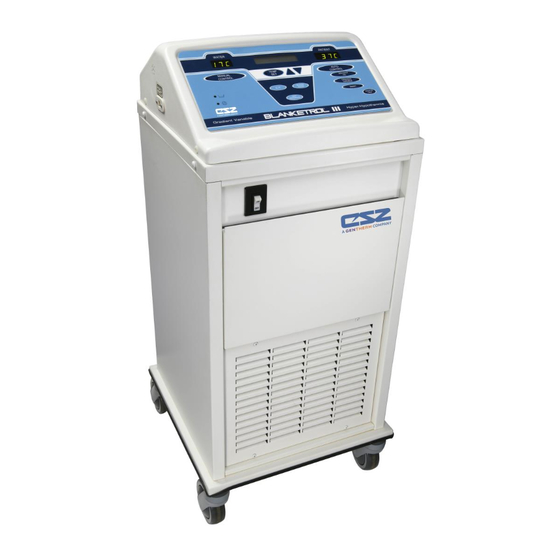
OPERATION BLANKETROL III, Model 233 OPERATION AND TECHNICAL MANUAL 1-3. PHYSICAL DESCRIPTION OF THE BLANKETROL III UNIT See Section (7.) for specifications and certifications of the BLANKETROL III. 1-3.1. External Features - Front View The external features in Figure (1-1.) of the BLANKETROL III unit are described as follows: The control panel is composed of pressure sensitive touch switches, nine LED indicators, a liquid crystal display, and two LED displays. -
Page 15: Figure 1-1. Blanketrol Iii - Front View
OPERATION BLANKETROL III, Model 233 OPERATION AND TECHNICAL MANUAL FIGURE 1-1. BLANKETROL III - FRONT VIEW Page 15 of 131... -
Page 16: 1-3.2. External Features - Right Side View
OPERATION BLANKETROL III, Model 233 OPERATION AND TECHNICAL MANUAL 1-3.2. External Features – Right Side View The external features in Figure (1-2.) of the BLANKETROL III unit are described as follows: The water flow indicator is a paddle wheel immersed in the path of the circulating water with a window to the outside. -
Page 17: Figure 1-2. Blanketrol Iii - Right Side
OPERATION BLANKETROL III, Model 233 OPERATION AND TECHNICAL MANUAL FIGURE 1-2. BLANKETROL III - RIGHT SIDE Page 17 of 131... -
Page 18: 1-3.3. External Features - Rear View
OPERATION BLANKETROL III, Model 233 OPERATION AND TECHNICAL MANUAL 1-3.3. External Features – Rear View The external features in Figure (1-3.) of the BLANKETROL III unit are described as follows: The specification label outlines the BLANKETROL III unit's electrical requirements and displays the serial and model numbers of the unit. -
Page 19: Figure 1-3. Blanketrol Iii - Rear View
OPERATION BLANKETROL III, Model 233 OPERATION AND TECHNICAL MANUAL FIGURE 1-3. BLANKETROL III - REAR VIEW Page 19 of 131... -
Page 20: 1-3.4. Description Of The Blanketrol Iii Membrane Control Panel
OPERATION BLANKETROL III, Model 233 OPERATION AND TECHNICAL MANUAL 1-3.4. Description of the BLANKETROL III Membrane Control Panel The membrane control panel as shown in Figure (1-4.A.) for English and (1-4.B.) for Symbols is composed of pressure sensitive touch switches and LED displays. The membrane control panel is divided into the following sections: The green LED display labeled WATER shows the water temperature in the BLANKETROL III equipment. -
Page 21: Figure 1-4.A. Blanketrol Iii - Membrane Control Panel (English)
OPERATION BLANKETROL III, Model 233 OPERATION AND TECHNICAL MANUAL FIGURE 1-4.A. BLANKETROL III - MEMBRANE CONTROL PANEL (English) FIGURE 1-4.B. BLANKETROL III - MEMBRANE CONTROL PANEL (Symbols) Page 21 of 131... -
Page 22: Required Accessories
OPERATION BLANKETROL III, Model 233 OPERATION AND TECHNICAL MANUAL 1-4. REQUIRED ACCESSORIES Operation of the BLANKETROL III System requires the use of the blanket(s) designed to circulate warm or cool distilled water, a connecting hose with quick-disconnect male and female fittings and, if any of the automatic modes are to be utilized, a 400 Series thermistor probe. -
Page 23: 1-5.2. Heating System
OPERATION BLANKETROL III, Model 233 OPERATION AND TECHNICAL MANUAL reading reaches Set Point, the system continues circulating the water through the system, but stops heating / cooling it. If the patient’s temperature reading deviates from Set Point, the unit will automatically resume full operation in GRADIENT 10C MODE until the patient's temperature again reaches Set Point. -
Page 24: 1-5.3. Cooling System
OPERATION BLANKETROL III, Model 233 OPERATION AND TECHNICAL MANUAL 1-5.3. Cooling System The BLANKETROL III cooling system is composed of a compressor, condenser, condenser fan, an evaporator coil, water temperature control, solenoid valve, hot gas by-pass valve, and two low temperature safety devices. - Page 25 OPERATION BLANKETROL III, Model 233 OPERATION AND TECHNICAL MANUAL cycles between heating and cooling the water in order to maintain the Set Point temperature. The unit is designed not to exceed or fall below the desired temperature. As a safety precaution, the BLANKETROL III System has three high temperature safety devices and two low temperature safety devices.
-
Page 26: 1-5.6. Usb Port Operation
OPERATION BLANKETROL III, Model 233 OPERATION AND TECHNICAL MANUAL 1-5.6. USB Port Operation Refer to CSZ manual 57059 for instructions and usage of the BLANKETROL III Data Export Software. CAUTION Do not make any connection to the USB port terminal while the device is also connected to a patient. -
Page 27: Section 2. General Preparation Of The Blanketrol Iii System
The transportation company is responsible for the shipment after it leaves the factory. If problems other than shipping damage are found, notify your Cincinnati Sub-Zero representative or the Factory. 2-3. - Page 28 OPERATION BLANKETROL III, Model 233 OPERATION AND TECHNICAL MANUAL Examine the power cord for cuts or exposed wires and the power plug for bent or missing prongs. Review Section (1-3.) to identify the features of the BLANKETROL III System. Collect and arrange the following equipment and supplies: Hyper-hypothermia blanket(s) described in Section (1-4.) and listed in Table (6-8.).
-
Page 29: 2-3.2. Completing A System Test Routine
OPERATION BLANKETROL III, Model 233 OPERATION AND TECHNICAL MANUAL Push the male coupling until it SNAPS into position 10. Gently pull the connecting hose to assure a positive connection Check that the blanket is laying flat and that the connecting hose to the unit is not twisted or pinched. - Page 30 OPERATION BLANKETROL III, Model 233 OPERATION AND TECHNICAL MANUAL Press the MONITOR ONLY button. 1. The LED in the corner of the MONITOR ONLY switch illuminates 2. An alarm sounds. 3. The Status Displays CHECK PROBE because no probe is attached. Press the TEMP SET switch.
- Page 31 OPERATION BLANKETROL III, Model 233 OPERATION AND TECHNICAL MANUAL CAUTION Use distilled water only. Do Not Use De-Ionized water. De-Ionized water may cause corrosion to plumbing system components. Do Not Use Tap Water. Minerals and deposits can clog plumbing system components. ...
- Page 32 OPERATION BLANKETROL III, Model 233 OPERATION AND TECHNICAL MANUAL The microprocessor board beeps each time it is pressed. The Set Point display changes; the numbers move down the scale. The longer the button is pressed the faster the digits change. When the button is released and repressed, the digits once again change slowly and then increase in speed.
- Page 33 OPERATION BLANKETROL III, Model 233 OPERATION AND TECHNICAL MANUAL The microprocessor board beeps. The LED in the corner of the button illuminates. The Status Display returns to set temperature mode. Press the Up arrow or the Down arrow so that the Set point displays 37°C (98.6°F). Set the patient probe to a temperature reading between 30°C –...
- Page 34 OPERATION BLANKETROL III, Model 233 OPERATION AND TECHNICAL MANUAL The above depends upon the relationship of the patient temperature to the Set Point temperature. Note that the Set Point may be displayed in Fahrenheit. The pump is activated. The heater or compressor may be activated. The water flow indicator on the right side panel begins to move.
- Page 35 OPERATION BLANKETROL III, Model 233 OPERATION AND TECHNICAL MANUAL Press the Up arrow or Down arrow to change the gradient variable offset to the desired value. The microprocessor board beeps. The offset in the Status Display changes. Press the GRADIENT VARIABLE button. The microprocessor board beeps.
-
Page 36: Unit And Patient Related Precautions
OPERATION BLANKETROL III, Model 233 OPERATION AND TECHNICAL MANUAL The above depends upon the relationship of the blanket water temperature to the Set Point temperature. Note that the Set Point may be displayed in Fahrenheit. The pump is activated. The heater or compressor may be activated. The water flow indicator on the right side panel begins to move. -
Page 37: Patient Preparation And Bedside Care
OPERATION BLANKETROL III, Model 233 OPERATION AND TECHNICAL MANUAL The BLANKETROL III unit is equipped with a circuit breaker in the I/O (on/off) power switch to protect against current overload. 2-5. PATIENT PREPARATION AND BEDSIDE CARE Effective use of the BLANKETROL III System must include proper patient care prior to and while using the hyper-hypothermia blanket(s). - Page 38 OPERATION BLANKETROL III, Model 233 OPERATION AND TECHNICAL MANUAL WARNING Basic static electricity or ESD training should include an introduction to the physics of electrostatic charge, the voltage levels that can occur in normal practice and the damage that can be done to electronic components if equipment is touched by an operator who is electrostatically charged.
- Page 39 OPERATION BLANKETROL III, Model 233 OPERATION AND TECHNICAL MANUAL WARNING Due to electromagnetic compatibility, the BLANKETROL III unit should not be used adjacent to or stacked with other equipment. Potential electromagnetic interference may result. Other equipment includes ventilators, patient monitors, anesthesia delivery equipment, etc. Electromagnetic interference refers to electronic devices unintentionally affecting the operation of each other by emitting electromagnetic energy.
- Page 40 OPERATION BLANKETROL III, Model 233 OPERATION AND TECHNICAL MANUAL CAUTION If the unit was shipped on its side, permit the unit to rest in an upright position for twelve (12) hours before operating due to refrigeration oil displacement. For safe handling and use of chemicals follow manufacturer guidelines.
-
Page 41: Section 3. Operating The Blanketrol Iii System
OPERATION BLANKETROL III, Model 233 OPERATION AND TECHNICAL MANUAL SECTION 3. OPERATING THE BLANKETROL III SYSTEM 3-1. INTRODUCTION This section describes how to operate the BLANKETROL III System in order to control a patient's temperature. First, collect the equipment and prepare the patient. Second, decide which mode of operation to use. - Page 42 OPERATION BLANKETROL III, Model 233 OPERATION AND TECHNICAL MANUAL CAUTION Use distilled water only. Do Not Use De-Ionized water. De-Ionized water may cause corrosion to plumbing system components. Do Not Use Tap Water. Minerals and deposits can clog plumbing system components. ...
- Page 43 OPERATION BLANKETROL III, Model 233 OPERATION AND TECHNICAL MANUAL If a single-patient use hyper-hypothermia blanket is used, connect the color coded couplings of the connecting hose to the blanket as described in the instructions packaged with each blanket. Check that the blanket is flat and the connecting hose is not twisted or pinched. The hyper-hypothermia blanket may be pre-cooled or pre-warmed before positioning the patient.
-
Page 44: Operating The Blanketrol Iii System In Auto Control Mode
OPERATION BLANKETROL III, Model 233 OPERATION AND TECHNICAL MANUAL Choose which operating mode to use: Operating in AUTO CONTROL MODE is described in Section (3-3.). Operating in MANUAL CONTROL MODE is described in Sections (3-4.) and (3-5.). Operating in GRADIENT 10C MODE is described in section (3-6.). - Page 45 OPERATION BLANKETROL III, Model 233 OPERATION AND TECHNICAL MANUAL and deliver the maximum heating or cooling therapy in order to bring the patient’s temperature to a Set Point chosen by the operator. After arranging the equipment as described in Section (3-2.), proceed as follows: Check the placement of the 400 Series probe in or on the patient.
- Page 46 OPERATION BLANKETROL III, Model 233 OPERATION AND TECHNICAL MANUAL The WATER display shows the actual temperature of the water in the BLANKETROL III equipment. The Status Display indicates: * XXXXXX PATIENT AUTO SETPT 37.0 C Or Status Display shows: PATIENT @SETPT AUTO SETPT 37.0 C * (”XXXXXX”...
-
Page 47: Operating The Blanketrol Iii System In Manual Control Mode
OPERATION BLANKETROL III, Model 233 OPERATION AND TECHNICAL MANUAL 3-4. OPERATING THE BLANKETROL III SYSTEM IN MANUAL CONTROL MODE WARNING A physician's order is required for setting blanket temperature and use of equipment. At least every 20 minutes, or as directed by physician, check patient's temperature and skin integrity of areas in contact with blanket;... - Page 48 OPERATION BLANKETROL III, Model 233 OPERATION AND TECHNICAL MANUAL Press the Up arrow or Down arrow to change the SETPOINT display to the desired Blanket/Water Set Point temperature. As a safety precaution, the Blanket/Water temperature in the device can only be set between 4°C - 42°C (39.2°F - 107.6°F). The microprocessor board beeps.
-
Page 49: Operating The Blanketrol Iii System In Manual Control Mode With The Addition Of The Patient Probe
OPERATION BLANKETROL III, Model 233 OPERATION AND TECHNICAL MANUAL NOTE: IN ORDER TO CHANGE FROM A MANUAL CONTROL MODE TO ANOTHER CONTROL MODE, FIRST PRESS THE “TEMP SET” BUTTON, AND THEN SELECT THE OPERATING MODE OF CHOICE. In order to change from MANUAL CONTROL MODE to MONITOR ONLY MODE, simply press the MONITOR ONLY button. -
Page 50: Operating The Blanketrol Iii System In Gradient 10C Mode
OPERATION BLANKETROL III, Model 233 OPERATION AND TECHNICAL MANUAL The BLANKETROL III System is now operating in MANUAL CONTROL MODE while monitoring the patient's temperature. However, you must also monitor the patient's temperature. (Review the suggestions for patient care described in Section (2-5.). If at any time the Status Display shows a message other than the messages described in MANUAL CONTROL MODE procedures, make the changes indicated by the display and/or consult the list of display messages in Section (3-12.). - Page 51 OPERATION BLANKETROL III, Model 233 OPERATION AND TECHNICAL MANUAL The BLANKETROL III System can be set to gradually change a patient’s temperature by maintaining the water in the BLANKETROL III equipment at a maximum temperature 10°C (18°F) different from the patient’s body temperature. After arranging the equipment as described in Section (3-2.), proceed as follows: Check the placement of the 400 Series probe in or on the patient.
- Page 52 OPERATION BLANKETROL III, Model 233 OPERATION AND TECHNICAL MANUAL The Status Display shows: * XXXXXX PATIENT AUTO SETPT 37.0 C Or Status Display shows: PATIENT @SETPT AUTO SETPT 37.0 C * (”XXXXXX” represents “HEATING” or “COOLING”.) The above depends upon the relationship of the patient temperature to the Set Point temperature.
-
Page 53: Operating The Blanketrol Iii Unit In Gradient 10C Smart Mode
OPERATION BLANKETROL III, Model 233 OPERATION AND TECHNICAL MANUAL 3-7. OPERATING THE BLANKETROL III UNIT IN GRADIENT 10C SMART MODE WARNING A physician's order is required for setting blanket temperature and use of equipment. At least every 20 minutes, or as directed by physician, check patient's temperature and skin integrity of areas in contact with blanket;... - Page 54 OPERATION BLANKETROL III, Model 233 OPERATION AND TECHNICAL MANUAL The switch illuminates green. The microprocessor board goes through self-test. The Status Display flashes CHECK SETPT. Consult the physician's orders to determine the desired patient Set Point temperature. As a safety precaution, the desired patient Set Point can only be set between 30°C - 40°C (86°F - 104°F) to operate in GRADIENT 10C SMART MODE.
-
Page 55: Operating The Blanketrol Iii System In Gradient Variable Mode
OPERATION BLANKETROL III, Model 233 OPERATION AND TECHNICAL MANUAL The water flow indicator on the right side panel begins to move. The water moves from the unit to the blanket and returns to the unit. Press the SMART key. The microprocessor board beeps. The LED on the SMART button illuminates. - Page 56 OPERATION BLANKETROL III, Model 233 OPERATION AND TECHNICAL MANUAL Basic static electricity or ESD training should include an introduction to the physics of electrostatic charge, the voltage levels that can occur in normal practice and the damage that can be done to electronic components if equipment is touched by an operator who is electrostatically charged.
- Page 57 OPERATION BLANKETROL III, Model 233 OPERATION AND TECHNICAL MANUAL The Set Point temperature in the Status Display changes. Press the GRADIENT VARIABLE button. The microprocessor board beeps. The LED in the corner of the button illuminates. The Status Display shows a gradient variable. Press the Up arrow or Down arrow to change the gradient variable offset to the desired value.
-
Page 58: Operating The Blanketrol Iii System In Gradient Variable Smart Mode
OPERATION BLANKETROL III, Model 233 OPERATION AND TECHNICAL MANUAL The BLANKETROL III System is now operating in GRADIENT VARIABLE MODE. You should continue to monitor the system and the patient. (Review the suggestions for patient care described in Section (2-5.). If at any time the Status Display shows a message other than the messages described in GRADIENT VARIABLE MODE procedures, make the changes indicated by the display and/or consult the list of display messages in Section (3-12.). - Page 59 OPERATION BLANKETROL III, Model 233 OPERATION AND TECHNICAL MANUAL The BLANKETROL III System can be set to gradually change the patient’s temperature according to specific patient’s needs by maintaining the water in the BLANKETROL III equipment at a specified temperature from the patient’s body temperature (as chosen by the operator). The system then increases this temperature difference by 5°C (9°F) every 30 minutes until the patient’s temperature reaches Set Point.
- Page 60 OPERATION BLANKETROL III, Model 233 OPERATION AND TECHNICAL MANUAL Press the Up arrow or Down arrow to change the gradient variable offset to the desired value. The microprocessor board beeps. The Set Point temperature in the Status Display changes. Press the GRADIENT VARIABLE button. The microprocessor board beeps.
-
Page 61: Operating The Blanketrol Iii System In Monitor Only Mode
OPERATION BLANKETROL III, Model 233 OPERATION AND TECHNICAL MANUAL The BLANKETROL III System is now operating in GRADIENT VARIABLE SMART MODE. You should continue to monitor the system and the patient. (Review the suggestions for patient care described in Section (2-5.). If at any time the Status Display shows a message other than the messages described in GRADIENT VARIABLE SMART MODE procedures, make the changes indicated by the display and/or consult the list of display messages in Section (3-12.). -
Page 62: Concluding Hyper-Hypothermia Treatment
OPERATION BLANKETROL III, Model 233 OPERATION AND TECHNICAL MANUAL The microprocessor board goes through self-test. The Status Display flashes CHECK SETPT. Press the MONITOR ONLY button. The microprocessor board beeps. The LED in the corner of the button illuminates. The Patient display shows the patient's temperature. The Status Display indicates MONITOR ONLY and the selected temperature scale. -
Page 63: Status Display Messages
OPERATION BLANKETROL III, Model 233 OPERATION AND TECHNICAL MANUAL Disconnect the power cord from the power source, loosely coil it and attach it to the back panel using the nylon strap. Disconnect the connecting hose from the unit and store in the front storage drawer. Remove the blanket(s). - Page 64 OPERATION BLANKETROL III, Model 233 OPERATION AND TECHNICAL MANUAL Status Display Message Function This message is displayed on the left side of the bottom line and indicates AUTO that the BLANKETROL III is operating in one of the five automatic modes. * (“xxx.x”...
- Page 65 OPERATION BLANKETROL III, Model 233 OPERATION AND TECHNICAL MANUAL This message occurs for the following three possible reasons, followed by their remedial actions: 1. During start up, when the operator turns the unit ON: a. Proceed by pressing the TEMP SET button to enter the Set Point temperature.
- Page 66 OPERATION BLANKETROL III, Model 233 OPERATION AND TECHNICAL MANUAL This message occurs when the software fails and the water in the BLANKETROL III equipment has reached the high temperature limit of 44.0°C 2°C (111.2°F 3.6°F), activating the independent safety. While this message is displayed, the trouble alarm will sound, and the heater and pump will turn off.
- Page 67 OPERATION BLANKETROL III, Model 233 OPERATION AND TECHNICAL MANUAL This message occurs when the software fails and the water in the BLANKETROL III equipment has reached the low temperature limit of 2.0°C 2°C (35.6°F 3.6°F), activating the independent safety. While this message is displayed, the trouble alarm will sound, and the compressor and pump will turn off.
- Page 68 OPERATION BLANKETROL III, Model 233 OPERATION AND TECHNICAL MANUAL This message is displayed to alert the operator when the probe needs to be checked. For instance: 1. If the probe is operating outside of the normal operating range of 30.0°C – 43.5°C (86°F to 110.3°F) during any automatic mode, this message will be displayed.
- Page 69 OPERATION BLANKETROL III, Model 233 OPERATION AND TECHNICAL MANUAL This message occurs when the float switch senses that the water in the reservoir is below a preset level or the float switch is defective. The trouble alarm sounds, the seven-segment displays will be blank, the low water symbol LED will flash, and the heater, compressor and pump will turn off.
- Page 70 OPERATION BLANKETROL III, Model 233 OPERATION AND TECHNICAL MANUAL This message displays the total number of hours of operation until the next required PM. To display this message, simultaneously press SILENCE ALARM and TEMP SET buttons. Note: 1. Maintenance should be performed at least quarterly or when indicated HOURS UNTIL SERVICE by 500 hour PM notification, whichever occurs first.
-
Page 71: Section 4. General Maintenance Of The Blanketrol Iii System
MAINTENANCE BLANKETROL III, Model 233 OPERATION AND TECHNICAL MANUAL SECTION 4. GENERAL MAINTENANCE OF THE BLANKETROL III SYSTEM 4-1. INTRODUCTION This section describes the general requirements maintenance personnel should complete on a regular basis so that the BLANKETROL III System continues to operate within the manufacturers’ allowable tolerances. -
Page 72: 4-1.1. Test Equipment Required
MAINTENANCE BLANKETROL III, Model 233 OPERATION AND TECHNICAL MANUAL 4-1.1. TEST EQUIPMENT REQUIRED The following test equipment is required to perform the preventive maintenance/functional check- out procedures: • CSZ's model TFRW 86171 Trimatic (Temperature Tester, Flow Meter, Resistance Tester) - Need Probe Extension Cable #TM-4A (Part # 39005) - Need Hose Assembly #TM-6 (Part # 91802) •... -
Page 73: Figure 4-1. Blanketrol Iii Maintenance Checklist
MAINTENANCE BLANKETROL III, Model 233 OPERATION AND TECHNICAL MANUAL FIGURE 4-1. BLANKETROL III MAINTENANCE CHECKLIST REQUIRED PREVENTIVE MAINTENANCE CHECKLIST (Quarterly or when indicated by 500 hour PM notification) BLANKETROL III - Model 233 Hospital Control No. Serial Number Check When Completed ... -
Page 74: Maintenance Of The Water Reservoir
MAINTENANCE BLANKETROL III, Model 233 OPERATION AND TECHNICAL MANUAL 4-2. MAINTENANCE OF THE WATER RESERVOIR The dual compartment reservoir holds approximately 2 gallons (7.6 liters) of distilled water that remains in the unit between periods of use. Quarterly, the water reservoir should be drained and replenished. - Page 75 MAINTENANCE BLANKETROL III, Model 233 OPERATION AND TECHNICAL MANUAL Note: The duration indicated in the CCC chart is meant to begin when the circulating water reaches the temperature indicated in the CCC chart. Drain the unit as instructed in Step #1. Rinse the unit three (3) times as described in Steps 4-6.
- Page 76 MAINTENANCE BLANKETROL III, Model 233 OPERATION AND TECHNICAL MANUAL If unit is to be returned to service, replenish reservoir(s) with the appropriate volume of distilled water. If unit is being placed in dry storage, continue with procedure. When all fluid has been removed from the unit, disconnect the drain hose(s) and wipe unit clean.
-
Page 77: 4-2.1. Draining The Reservoir
MAINTENANCE BLANKETROL III, Model 233 OPERATION AND TECHNICAL MANUAL 4-2.1. Draining the Reservoir CAUTION Always drain the BLANKETROL III to a sanitary drain because bio-contaminants may be present in the unit’s water supply. Collect these items: An empty container to drain the water into that can hold at least 3 gallons (11.4 liters). -
Page 78: 4-2.2. Replenishing The Reservoir
MAINTENANCE BLANKETROL III, Model 233 OPERATION AND TECHNICAL MANUAL After all the water has drained from the unit, disconnect the drain hose, wipe, clean and store in a dry environment without disinfecting. (Refer to Section (7.) specifications for storage conditions) Discard the water drained from the unit. - Page 79 MAINTENANCE BLANKETROL III, Model 233 OPERATION AND TECHNICAL MANUAL After draining the reservoir as described in Section (4-2.1.): Disconnect the unit from its power source. WARNING The repair, calibration, and servicing of the BLANKETROL III should be performed by qualified Medical Equipment Service Technicians, Certified Biomedical Electronics Technicians, or Certified Clinical Engineers familiar with good repair practices for servicing medical devices, and in accordance with instructions contained in this manual.
-
Page 80: Maintenance Of The Condenser And Grill
General maintenance tasks include cleaning, draining, and storing the blankets. 4.6.1 Reusable Blanket Cincinnati Sub-Zero reusable blankets are constructed from biocompatible polyurethane/urethane. Stains and debris can be wiped away with mild soap and water. For cleaning and disinfecting, always use conventional hospital-approved topical cleaners and disinfectants that do not contain alcohol. -
Page 81: 4-6.2. Disposable, Single-Patient Use Blankets
MAINTENANCE BLANKETROL III, Model 233 OPERATION AND TECHNICAL MANUAL To drain the water from the reusable blankets simply shut off power to the unit or shut off the operation of the manual or automatic mode and allow the water to drain from the blanket back into the BLANKETROL III unit. -
Page 82: Low Limit Safeties Check
MAINTENANCE BLANKETROL III, Model 233 OPERATION AND TECHNICAL MANUAL 4-8. LOW LIMIT SAFETIES CHECK WARNING The repair, calibration, and servicing of the BLANKETROL III should be performed by qualified Medical Equipment Service Technicians, Certified Biomedical Electronics Technicians, or Certified Clinical Engineers familiar with good repair practices for servicing medical devices, and in accordance with instructions contained in this manual. -
Page 83: High Limit Safeties Check
MAINTENANCE BLANKETROL III, Model 233 OPERATION AND TECHNICAL MANUAL 4-9. HIGH LIMIT SAFETIES CHECK WARNING The repair, calibration, and servicing of the BLANKETROL III should be performed by qualified Medical Equipment Service Technicians, Certified Biomedical Electronics Technicians, or Certified Clinical Engineers familiar with good repair practices for servicing medical devices, and in accordance with instructions contained in this manual. -
Page 84: Temperature Accuracy Check
MAINTENANCE BLANKETROL III, Model 233 OPERATION AND TECHNICAL MANUAL Turn the BLANKETROL III off and remove the test jumper. Allow the water temperature to fall below 42.0°C and turn the BLANKETROL III back Confirm that the thermostatic disc has reset by verifying that EE02 is not shown in the patient display. -
Page 85: Section 5. Field Repair/Service Of The Blanketrol Iii Unit
FIELD REPAIR/SERVICE BLANKETROL III, Model 233 OPERATION AND TECHNICAL MANUAL SECTION 5. FIELD REPAIR/SERVICE OF THE BLANKETROL III UNIT WARNING Always unplug the unit before accessing internal components during service. Failure to unplug the unit could result in electric shock. ... - Page 86 FIELD REPAIR/SERVICE BLANKETROL III, Model 233 OPERATION AND TECHNICAL MANUAL Figures (5-1.), (6-2.), and (6-4.) highlight the interior components of the BLANKETROL III unit. The internal components referenced in Figure (5-1.) are as follows: A. Upper manifold (return) B. Water temperature sensor C.
-
Page 87: Figure 5-1. Blanketrol Iii - Exposed Rear View
FIELD REPAIR/SERVICE BLANKETROL III, Model 233 OPERATION AND TECHNICAL MANUAL FIGURE 5-1. BLANKETROL III - EXPOSED REAR VIEW Page 87 of 131... -
Page 88: Access To The Interior Of The Blanketrol Iii Unit
FIELD REPAIR/SERVICE BLANKETROL III, Model 233 OPERATION AND TECHNICAL MANUAL 5-2. ACCESS TO THE INTERIOR OF THE BLANKETROL III UNIT All internal operating components are readily accessible by removing the rear enclosure panel, removing the top of the unit, or extending the front storage drawer. NOTE: DRAIN THE RESERVOIR AND DISCONNECT THE POWER CORD FROM THE POWER SOURCE BEFORE REMOVING ANY PART FROM THE UNIT. -
Page 89: 5-2.3. Removing The Left Side Enclosure Panel
FIELD REPAIR/SERVICE BLANKETROL III, Model 233 OPERATION AND TECHNICAL MANUAL If work is to be done with the microprocessor board, the membrane control panel, or anything related to the top assembly, disconnect the cables from the microprocessor board. Go to Section (5-2.4.). -
Page 90: 5-2.5. Extending The Front Storage Drawer
FIELD REPAIR/SERVICE BLANKETROL III, Model 233 OPERATION AND TECHNICAL MANUAL CONNECTOR J POSITION Red 2-position flow switch connector J9 position Red 9-position connector J8 position White 2-position connector J4 position White 12-position connector J1 position Red 3-position connector J3 position Blue 11-position membrane ribbon cable J7 position connector... -
Page 91: Replacement Of The Heater
FIELD REPAIR/SERVICE BLANKETROL III, Model 233 OPERATION AND TECHNICAL MANUAL B. Using a Phillips head screwdriver, replace the 8-32 screw on the right side of the inside of the panel. 5-3. REPLACEMENT OF THE HEATER WARNING Always unplug the unit before accessing internal components during service. Failure to unplug the unit could result in electric shock. -
Page 92: Replacement Of The Pump Housing
FIELD REPAIR/SERVICE BLANKETROL III, Model 233 OPERATION AND TECHNICAL MANUAL CAUTION Always drain the BLANKETROL III to a sanitary drain because bio-contaminants may be present in the unit’s water supply. Drain the reservoir as described in Section (4-2.1.). Extend the front storage drawer as described in section (5-2.5). Locate the T-Shaped water filter assembly tucked under the water reservoir. -
Page 93: Replacement Of The Pump Motor
FIELD REPAIR/SERVICE BLANKETROL III, Model 233 OPERATION AND TECHNICAL MANUAL Disconnect the hose at the inlet of the pump housing by loosening the screw clamp. Be careful: there may be water in the hose. Disconnect the hose at the outlet of the pump housing by loosening the screw clamp near the top of the white pump housing. - Page 94 FIELD REPAIR/SERVICE BLANKETROL III, Model 233 OPERATION AND TECHNICAL MANUAL Remove the rear enclosure panel as described in Section (5-2.1.). Extend the front storage drawer as described in Section (5-2.5.). Locate the pump housing assembly with inlet and outlet hose connections at the center left of the rear of the unit as shown in Figure (5-1-D.).
-
Page 95: Replacement Of The Flow Switch
FIELD REPAIR/SERVICE BLANKETROL III, Model 233 OPERATION AND TECHNICAL MANUAL Install the electrical box cover and using a 11/32 inch wrench, tighten the two 5/16 inch nuts to the stand offs. Refill the reservoir as described in Section (4-2.2.). Complete the applicable parts of the First Time Set-Up/System Test Routine in Section (2-3.) to determine that the pump is circulating the water. -
Page 96: Replacement Of The Water Temperature Sensor
FIELD REPAIR/SERVICE BLANKETROL III, Model 233 OPERATION AND TECHNICAL MANUAL Feed the flow switch wire harness carefully towards the flow switch, removing any wire ties as needed. Discard the old flow switch. Install the new flow switch by reversing the removal instructions above. Refill the reservoir as described in Section (4-2.2.). -
Page 97: Replacement Of The Upper And/Or Lower Water Manifolds
FIELD REPAIR/SERVICE BLANKETROL III, Model 233 OPERATION AND TECHNICAL MANUAL WARNING Always unplug the unit before accessing internal components during service. Failure to unplug the unit could result in electric shock. CAUTION Always drain the BLANKETROL III to a sanitary drain because bio-contaminants may be present in the unit’s water supply. -
Page 98: Replacement Of The Compressor Starting Capacitor, The Overload Protector, And/Or The Compressor Relay
FIELD REPAIR/SERVICE BLANKETROL III, Model 233 OPERATION AND TECHNICAL MANUAL Connect the hose from the pump housing to the copper elbow of the manifold and tighten the clamp. Remove the used white Teflon tape from around the threads of the water temperature sensor. -
Page 99: Replacement Of The Thermal Disc Over Temperature Device
FIELD REPAIR/SERVICE BLANKETROL III, Model 233 OPERATION AND TECHNICAL MANUAL 5-11. REPLACEMENT OF THE THERMAL DISC OVER TEMPERATURE DEVICE WARNING Always unplug the unit before accessing internal components during service. Failure to unplug the unit could result in electric shock. Obtain a replacement thermal disc. - Page 100 FIELD REPAIR/SERVICE BLANKETROL III, Model 233 OPERATION AND TECHNICAL MANUAL Locate the water flow indicator assembly (number 12 in Figure 6-2.) attached to the right side (front view) wall, the connecting hose at its top left and the connecting hose at its top right. Disconnect the hose at the top left of the water flow indicator by loosening the screw clamp.
-
Page 101: Replacement Of The I/O Power Switch
FIELD REPAIR/SERVICE BLANKETROL III, Model 233 OPERATION AND TECHNICAL MANUAL 5-13. REPLACEMENT OF THE I/O POWER SWITCH WARNING Always unplug the unit before accessing internal components during service. Failure to unplug the unit could result in electric shock. Obtain the replacement I/O power switch. Extend the front storage drawer as described in Section (5-2.5.). -
Page 102: Replacement Of The Microprocessor Board And/Or The Membrane Control Panel
FIELD REPAIR/SERVICE BLANKETROL III, Model 233 OPERATION AND TECHNICAL MANUAL Locate the water level sensor. Facing the unit, it is a square plate located in the center of the unit with two red wires leading to a 2-pin connector. Number 15 in Figure (6-2.). -
Page 103: Replacement Of The Beeper Assembly
FIELD REPAIR/SERVICE BLANKETROL III, Model 233 OPERATION AND TECHNICAL MANUAL Using a 5/16" wrench remove the six nuts around the edge of the board. Gently lift and remove the microprocessor board. Carefully set the microprocessor board aside. If only the microprocessor board is to be replaced, go to Step K. If the membrane control panel is to be replaced, go to Step G. -
Page 104: Replacement Of The Power Cord
FIELD REPAIR/SERVICE BLANKETROL III, Model 233 OPERATION AND TECHNICAL MANUAL Discard the defective beeper and reinstall the enclosure panels and the top of the unit. Installation is reverse of removal. 5-17. REPLACEMENT OF THE POWER CORD A. Disconnect and remove each of the wires from the electrical box. The white and black wires are terminated with slide-off connector. -
Page 105: 5-18.2. Taking Measurements In Normal Polarity
FIELD REPAIR/SERVICE BLANKETROL III, Model 233 OPERATION AND TECHNICAL MANUAL 5-18.2. Taking Measurements in Normal Polarity A. Set the tester to Normal Polarity. B. Push the power switch of the BLANKETROL III unit to the “I” position and record the Leakage Current. -
Page 106: Troubleshooting Guide
FIELD REPAIR/SERVICE BLANKETROL III, Model 233 OPERATION AND TECHNICAL MANUAL TROUBLESHOOTING GUIDE 5-20. TROUBLESHOOTING GUIDE OBSERVATION POSSIBLE ACTION TO BE TAKEN PROBLEM Check that the power cord is A. The power switch of the plugged into a properly BLANKETROL III unit is Unit is unplugged grounded hospital grade set on, in “I”... - Page 107 FIELD REPAIR/SERVICE BLANKETROL III, Model 233 OPERATION AND TECHNICAL MANUAL TROUBLESHOOTING GUIDE OBSERVATION POSSIBLE ACTION TO BE TAKEN PROBLEM E. Unit is on, any switch on the membrane control panel is pressed but does not stay set, or when the Membrane switch has Replace membrane control operating mode is...
- Page 108 FIELD REPAIR/SERVICE BLANKETROL III, Model 233 OPERATION AND TECHNICAL MANUAL TROUBLESHOOTING GUIDE OBSERVATION POSSIBLE ACTION TO BE TAKEN PROBLEM Cable from the 1/4 inch receptacle to microprocessor board is Reconnect cable (J8 disconnected, Status position on microprocessor H. The probe from the Display flashes CHECK board).
- Page 109 FIELD REPAIR/SERVICE BLANKETROL III, Model 233 OPERATION AND TECHNICAL MANUAL TROUBLESHOOTING GUIDE OBSERVATION POSSIBLE ACTION TO BE TAKEN PROBLEM Other than a 400 Series probe was connected to the 1/4 inch receptacle. Replace with the correct 400 Series probe (refer to Table (6-8.)).
- Page 110 FIELD REPAIR/SERVICE BLANKETROL III, Model 233 OPERATION AND TECHNICAL MANUAL TROUBLESHOOTING GUIDE OBSERVATION POSSIBLE ACTION TO BE TAKEN PROBLEM M. The unit is operating in MANUAL Water temperature Replace water temperature CONTROL MODE or sensor is defective. sensor. See Section (5-8.). one of the automatic modes and the Microprocessor board is...
- Page 111 FIELD REPAIR/SERVICE BLANKETROL III, Model 233 OPERATION AND TECHNICAL MANUAL TROUBLESHOOTING GUIDE OBSERVATION POSSIBLE ACTION TO BE TAKEN PROBLEM The High Limit Safety device is triggered which shuts down the unit when the water in the Replace microprocessor P. Unit is operating in BLANKETROL III board.
- Page 112 FIELD REPAIR/SERVICE BLANKETROL III, Model 233 OPERATION AND TECHNICAL MANUAL TROUBLESHOOTING GUIDE OBSERVATION POSSIBLE ACTION TO BE TAKEN PROBLEM The back-up low limit safety device is triggered which shuts Replace microprocessor down the unit when the board. See Section (5-15.). water in the BLANKETROL III R.
- Page 113 FIELD REPAIR/SERVICE BLANKETROL III, Model 233 OPERATION AND TECHNICAL MANUAL TROUBLESHOOTING GUIDE OBSERVATION POSSIBLE ACTION TO BE TAKEN PROBLEM T. Unit is set to operate Clogged tubing of Use forced air to drain in a control mode; the blankets. blankets. water flow indicator does not move, i.e.: water not circulating.
- Page 114 FIELD REPAIR/SERVICE BLANKETROL III, Model 233 OPERATION AND TECHNICAL MANUAL TROUBLESHOOTING GUIDE OBSERVATION POSSIBLE ACTION TO BE TAKEN PROBLEM Operator error; switches Correctly set switches. See not set correctly. Section (3.). V. Unit is set to operate in a control mode. Water not circulating.
-
Page 115: Section 6. Parts Information
SPECIFICATIONS BLANKETROL III, Model 233 OPERATION AND TECHNICAL MANUAL SECTION 6. PARTS INFORMATION 6-1. INTRODUCTION This section outlines information for ordering, shipping and replacing parts of the BLANKETROL III unit, Model 233. Identification of parts and components are shown in Figures (6-1.) and (6-3.). The numbers in Figures (6-2.) and (6-4.) correspond to the numbers in the left column of the accompanying parts list in Figures (6-1.) and (6-3.). -
Page 116: Returning Parts Under Warranty
6-4. RETURNING PARTS UNDER WARRANTY All parts are covered by a two (2) year warranty. To replace parts during the warranty period*, send the part prepaid to: Cincinnati Sub-Zero Products, LLC 12011 Mosteller Road Cincinnati, Ohio 45241 Tel: 1-800-989-7373 Fax: (513) 772-9119... -
Page 117: Figure 6-1. Parts List A
SPECIFICATIONS BLANKETROL III, Model 233 OPERATION AND TECHNICAL MANUAL INTERNAL EXPLODED - FRONT VIEW Index # Description White Reservoir Lid. 1/4 Inch Receptacle (“Probe Jack”) Assembly USB Cable Membrane Control Panel (115V and P/N 86204) Membrane Control Panel (230V and P/N 86102) Top Assembly (115V) Top Assembly (230V) White Reservoir Lid Assembly (115V) -
Page 118: Figure 6-2. Blanketrol Iii - Internal Exploded - Front View
SPECIFICATIONS BLANKETROL III, Model 233 OPERATION AND TECHNICAL MANUAL FIGURE 6-2. BLANKETROL III - INTERNAL EXPLODED - FRONT VIEW Page 118 of 131... -
Page 119: Figure 6-3. Parts List B
SPECIFICATIONS BLANKETROL III, Model 233 OPERATION AND TECHNICAL MANUAL INTERNAL EXPLODED - REAR VIEW Index # Description Top Assembly (115V and P/N 86204) Top Assembly (230V and P/N 86102) Patient Probe Label Screw Snap Cap Overflow Drain Hose Barb Drawer Stop - 8-32 x 1/2 Shoulder Bolt Nylon Shoulder Washer Storage Drawer Assembly... -
Page 120: Figure 6-4. Blanketrol Iii - Internal Exploded - Rear View
SPECIFICATIONS BLANKETROL III, Model 233 OPERATION AND TECHNICAL MANUAL FIGURE 6-4. BLANKETROL III - INTERNAL EXPLODED - REAR VIEW Page 120 of 131... -
Page 121: Figure 6-5.A. Blanketrol Iii - Electrical Wiring Diagram - 115 Volt
SPECIFICATIONS BLANKETROL III, Model 233 OPERATION AND TECHNICAL MANUAL FIGURE 6-5.A. BLANKETROL III - ELECTRICAL WIRING DIAGRAM - 115 VOLT Note: Beeper is located on the board for most devices built before 2nd quarter 2012. Page 121 of 131... -
Page 122: Figure 6-5.B. Blanketrol Iii - Electrical Wiring Diagram - 230 Volt
SPECIFICATIONS BLANKETROL III, Model 233 OPERATION AND TECHNICAL MANUAL FIGURE 6-5.B. BLANKETROL III - ELECTRICAL WIRING DIAGRAM - 230 VOLT Note: Beeper is located on the board for most devices built before 2nd quarter 2012. Page 122 of 131... -
Page 123: Figure 6-6. Blanketrol Iii - Water Circulation Diagram
SPECIFICATIONS BLANKETROL III, Model 233 OPERATION AND TECHNICAL MANUAL FIGURE 6-6. BLANKETROL III - WATER CIRCULATION DIAGRAM Page 123 of 131... -
Page 124: Figure 6-7. Blanketrol Iii - Refrigeration Flow Diagram
SPECIFICATIONS BLANKETROL III, Model 233 OPERATION AND TECHNICAL MANUAL FIGURE 6-7. BLANKETROL III - REFRIGERATION FLOW DIAGRAM Page 124 of 131... -
Page 125: Table 6-8. Blanketrol Iii System Accessories
SPECIFICATIONS BLANKETROL III, Model 233 OPERATION AND TECHNICAL MANUAL TABLE 6-8. BLANKETROL III SYSTEM ACCESSORIES WARNING Use of accessories other than specified below may result in increased electromagnetic emissions or decreased immunity to electromagnetic emissions of the BLANKETROL III unit. This could affect the BLANKETROL III’s compatibility with other electrical equipment. - Page 126 SPECIFICATIONS BLANKETROL III, Model 233 OPERATION AND TECHNICAL MANUAL Miscellaneous USB-127 Data Export Software TFRW Tri-matic Tester TEMPERATURE PROBES 400 Series Reusable Probes Adult (Esophageal or Rectal) Infant (Esophageal or Rectal) Attachable, Surface Temperature - Tape on Skin Probe Extension Cord (10' Length) Disposable Temperature Probes –...
-
Page 127: Section 7. Specifications And Certifications Of The Blanketrol Iii
SPECIFICATIONS BLANKETROL III, Model 233 OPERATION AND TECHNICAL MANUAL SECTION 7. SPECIFICATIONS AND CERTIFICATIONS OF THE BLANKETROL III BLANKETROL III MODEL 233 FEATURES PHYSICAL SAFETY SYSTEM Dimensions: 17"W x 17"D x 37.5"H (43.18cm.W x 43.18 Maximum High Control Setting: cm. D x 95.25cm.H) 42.0°C (107.6°F) Weight: Empty -131 lbs. - Page 128 SPECIFICATIONS BLANKETROL III, Model 233 OPERATION AND TECHNICAL MANUAL BLANKETROL III MODEL 233 FEATURES (CONT.) CONTROL SYSTEM (cont’d) CONTROL SYSTEM Microprocessor controlled, Lighted "OFF-ON" power Display Type: switch, Digital LED Read Outs, Alarm Indications, and Temp. Settings: Mode Indications. Water Temp.: 0.1°C (0.1°F) Controller Range: Patient Temp.:...
-
Page 129: Table 7-1. Guidance And Manufacturer's Declaration - Electromagnetic Emissions
SPECIFICATIONS BLANKETROL III, Model 233 OPERATION AND TECHNICAL MANUAL The following tables are presented in fulfillment of the requirements of IEC 60601-1-2 TABLE 7-1. GUIDANCE AND MANUFACTURER'S DECLARATION - ELECTROMAGNETIC EMISSIONS The BLANKETROL III, Model 233 is intended for use in the electromagnetic environment specified below. The customer or the user of the BLANKETROL III, Model 233 should assure that it is used in such an environment. -
Page 130: Table 7-3. Guidance And Manufactuerer's Declaration - Electromagnetic Immunity
SPECIFICATIONS BLANKETROL III, Model 233 OPERATION AND TECHNICAL MANUAL TABLE 7-3. GUIDANCE AND MANUFACTUERER'S DECLARATION - ELECTROMAGNETIC IMMUNITY The BLANKETROL III, Model 233 is intended for use in the electromagnetic environment specified below. The customer or the user of the BLANKETROL III, Model 233 should assure that it is used in such an environment. Immunity test IEC 60601 test level Compliance level... -
Page 131: Worldwide Order Placement
SPECIFICATIONS BLANKETROL III, Model 233 OPERATION AND TECHNICAL MANUAL TABLE 7-4. RECOMMENDED SEPARATION DISTANCES BETWEEN PORTABLE AND MOBILE RF COMMUNICATIONS EQUIPMENT AND THE BLANKETROL III, MODEL 233 The BLANKETROL III, Model 233 is intended for use in an electromagnetic environment in which radiated RF disturbances are controlled. - Page 132 Cincinnati Sub-Zero Products, LLC 12011 Mosteller Road Cincinnati, OH 45241 Toll Free: 1-800-989-7373 Fax: (513) 772-9119 www.cszmedical.com...
Need help?
Do you have a question about the BLANKETROL III 233 and is the answer not in the manual?
Questions and answers