
Related Manuals for CENTURION SYSTEMS VANTAGE 400


Summary of Contents for CENTURION SYSTEMS VANTAGE 400
- Page 1 VANTAGE Mechanical Installation Manual Centurion Systems (Pty) Ltd www.CentSys.com page 1 www.CentSys.com...
- Page 2 Americas, Australia and the Pacific Centurion Systems (Pty) Ltd reserves the right to make changes to the products described in this manual without notice and without obligation of Centurion Systems (Pty) Ltd to notify any persons of any such revisions or changes. Additionally, Centurion Systems (Pty) Ltd makes no representations or warranties with respect to this manual.
-
Page 3: Table Of Contents
Contents SAFETY page 5 IMPORTANT SAFETY INSTRUCTIONS FIRST General Description page 8 Icons Used in this Manual page 9 Specifications page 10 page 10 3.1. Physical Dimensions page 11 3.2. Technical Specifications 3.3. V-Series Controller page 12 3.4. Lightning Protection page 12 page 12 3.5. - Page 4 FAST TRACK Mechanical Setup These quick steps are for the experienced installer who needs a checklist to get a standard installation up and running in the minimum of time. Detailed installation features and functions are referred to later in this manual. STEP Gather Required Tools and Equipment STEP...
-
Page 5: Safety First Important Safety Instructions
IMPORTANT SAFETY INSTRUCTIONS ATTENTION To ensure the safety of people and possessions, it is important that you read all the following instructions. Incorrect installation or incorrect use of the product could cause serious harm to people. The installer, being either professional or DIY, is the last person on the site who can ensure that the operator is safely installed, and that the whole system can be operated safely. - Page 6 Always check the obstruction detection system, and safety devices for correct operation • Neither Centurion Systems (Pty) Ltd, nor its subsidiaries, accept any liability caused by improper use of the product, or for use other than that for which the automated system was intended •...
- Page 7 This section has been left blank intentionally. www.CentSys.com page 7...
-
Page 8: General Description
1. General Description The VANTAGE linear swing gate motor, available in two models with actuation strokes of 400mm and 500mm, respectively, has been designed to automate a wide variety of swing gates, from single light-domestic gates to heavy industrial double swing gates. The fail-safe and fully-redundant Position and Collision Detection System has been designed and tested to set the standard in safety of operation and to provide an unparalleled level of reliability and durability in operation. -
Page 9: Icons Used In This Manual
2. Icons Used in this Manual This icon indicates tips and other information that could be useful during the installation. This icon denotes variations and other aspects that should be considered during installation. This icon indicates warning, caution or attention! Please take special note of critical aspects that MUST be adhered to in order to prevent injury. -
Page 10: Specifications
3. Specifications 3.1. Physical Dimensions 1370mm extended 970mm retracted 400mm extended piston stroke Ø100mm FIGURE 1. VANTAGE 400 OVERALL DIMENSIONS 1570mm extended 1070mm retracted 500mm extended Ø100mm piston stroke FIGURE 2. VANTAGE 500 OVERALL DIMENSIONS page 10 www.CentSys.com... -
Page 11: Technical Specifications
3.2. Technical Specifications - VANTAGE Operator VANTAGE 400 VANTAGE 500 Input voltage 90V - 240V AC ± 10%, 50/60Hz Motor voltage 12V DC Motor power supply Battery-driven (standard capacity - 7Ah) Battery charger 1.8A @ 13.8V Current consumption (Mains) 170mA... -
Page 12: V-Series Controller
3.3. V-Series Controller Maximum motor current per channel 15A (fused) Maximum input voltage 14.4V DC Standby current draw 48mA Maximum solenoid current draw 2A DC Maximum auxillary output current 3A (Resettable Electronic Fuse) Collision detection Current sense and redundant-optical Position and trajectory control Redundant optical Temperature range -20°C to +60°C... -
Page 13: Allowable Gate Mass
3.6. Allowable Gate Mass Ensure that the gate leaf meets Wind Load Specifications Maximum allowable gate mass for the VANTAGE 400 operator Gate Up to Up to Up to Up to Up to Up to swing 1.5m 2.5m 3.5m angle 90°... -
Page 14: Allowable Wind Load
3.7. Allowable Wind Load Wind speeds for which operator will still operate the gate. (VANTAGE 400 or VANTAGE 500 operators) For a 25% covered gate: (Palisades, etc.) x 1.8 metre high Value of Individual gate leaf lengths: A or B... -
Page 15: Product Identification
4. Product Identification FIGURE 3. KIT IDENTIFICATION 1. Gate Bracket pin 7. Gate operator keys 2. 14mm snap ring 8. Stainless steel cap screw M5 x 25 3. VANTAGE gate operator 9. Origin clamp (complete assembly) 10. M5 barrel nut 4. -
Page 16: V-Series Wall Box
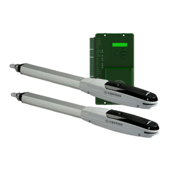
4.1. V-Series Wall Box FIGURE 4. V-SERIES WALL BOx INCLUDING CHARGER AND CONTROLLER 1. 12V 7.2Ah Battery 4. V-Series Electrical Setup & Commissioning Guide 2. V-Series Controller with built-in receiver 5. Charger 3. V-Series User Guide 6. Code-hopping remote controls 1. -
Page 17: Required Tools And Equipment
5. Required Tools & Equipment Screwdrivers 6mm Phillips 3.5mm Flat Pliers Hammer Electric drilling machine Spanners 17mm/15mm preferably socket set Connector Crimping tool block and Pin lugs G-clamps Hole saw Allen key 20mm Angle grinder Pin punch Measuring tape Ø12mm masonry drill bit for wall mount bracket Ø6.5mm steel drill bit for gate bracket... -
Page 18: Preparation Of Site
6. Preparation of Site 6.1. General Consideration for the Installation Always recommend the fitment of additional safety equipment such as safety edges and Safety Beams (i5 or Photon), for additional protection against entrapment or other mechanical risks. Check that no pipes or electrical cables are in the way of the intended installation. Check that enough space is available for the gate operator with the gate in the required open position (see Figure 6). -
Page 19: Determine Gate Opening Angle
6.2. Determine Gate Opening Angle Use this procedure to accurately determine the gate opening angle: 6.2.1. Step 1 Close the gate and measure a Mark the ground Wall distance of one metre from the 1 metre centreline of the gate hinge. Make a mark on the ground. -
Page 20: Key Terms Used In This Section
6.3. Key Terms Used in this Section 6.3.1. Pillar maximum The maximum allowable distance measured from the centre of the gate hinge to the edge of the pillar. 6.3.2. Wall minimum This value denotes the minimum amount of space needed to install the operator and is measured from the side wall to the gate when the gate is in the open position. -
Page 21: Pillar Hinge Depth Limitation - Inward Opening
Gate in closed position Pillar maximum Gate swing angle Gate in open position FIGURE 8. PILLAR HINGE DEPTH LIMITATION FOR INWARD OPENING GATE Operator Pillar Maximum Swing Gate Angle VANTAGE 400 175mm 90° VANTAGE 400 155mm 100° VANTAGE 400 145mm 110°... -
Page 22: Wall Bracket Mounting Methods
6.6. Wall Bracket Mounting Methods The following recommended methods may be used to install the operator. Pillar 6.6.1. Through-wall Applications: • Pre-fabricated walling Wall Bracket • For heavy gates operating frequently Through-wall bolt FIGURE 9 Pillar 6.6.2. Chemical anchors Applications: •... - Page 23 Pillar 6.6.4. Sleeve anchors Applications: • Lighter gates Wall Bracket • Domestic Sleeve anchor FIGURE 12 Pillar 6.6.5. Rawl bolts Applications: • Lighter gates Wall Bracket • Domestic Rawl bolt FIGURE 13 www.CentSys.com page 23...
-
Page 24: Strength Of The Gate And Gate Bracket
6.7. Strength of the Gate and Gate Bracket Gate 6.7.1. Welding Applications: • Domestic • Medium gates Gate Bracket • Frequent use Welding machine FIGURE 14 6.7.2. Through-bolts Gate Through-bolts (high-tensile) Applications: • Domestic • Light gates • Infrequent use Gate Bracket TEK screws and mild steel bolts are not recommended. -
Page 25: Cabling Requirements
7. Cabling Requirements Control Control Mains Mains isolator isolator switch switch 350mm cable loop FIGURE 16. CABLING REQUIREMENTS Legend 1. 90V - 240V AC Mains cable via Mains isolator switch (3 core LNE 0,5mm or low-voltage 16V AC battery charger supply (2 core 1,5mm²). -
Page 26: Critical Installation Checklist
8. Critical Installation Checklist The following is a list of critical requirements that must be adhered to in order to ensure reliable operation of your VANTAGE operator(s): • Ensure that the Wall Bracket is securely anchored • Make sure that the operator’s maximum stroke is being utilised •... -
Page 27: Operator Installation - Inward Opening Gates
21. Solar Panel Wiring 9. Operator Installation - Inward Opening Gates Figure 17 illustrates the values corresponding to the Inward Opening Gate Installation Tables. Wall Gate in closed position VANTAGE operator The length of the wall bracket should equal B minus E. When looking at the example above, the wall bracket should measure 240mm (B) - 160mm (E) = 80mm (wall bracket length) FIGURE 17. - Page 28 Example: 90° Inward Opening gate (VANTAGE 400): Assume that the E-Value has been measured as 160mm. By looking at this Table at E-Values that are smaller than (<) 165mm, the relevant A- and B-Values are: A=145mm and B=240mm. E-Value Depth of gate hinge...
- Page 29 VANTAGE 400 Inward Opening Gate Geometry Tables: 90° Inward Opening Gate E-Value Depth of gate hinge A-Value B-Value to pillar <145mm 170mm 220mm <155mm 160mm 230mm <165mm 145mm 240mm <175mm 130mm 250mm TABLE 10 1. Optimum Installation 100° Inward Opening Gate...
- Page 30 VANTAGE 500 Inward Opening Gate Geometry Tables: 90° Inward Opening Gate E -Value Depth of gate hinge A-Value B-Value to pillar <190mm 205mm 280mm <205mm 195mm 290mm <215mm 180mm 300mm <225mm 170mm 310mm <235mm 155mm 320mm <245mm 140mm 330mm TABLE 13 1.
- Page 31 VANTAGE 500 Inward Opening Gate Geometry Table: 110° Inward Opening Gate E-Value Depth of gate hinge A-Value B-Value to pillar <150mm 190mm 240mm <160mm 185mm 250mm <170mm 175mm 260mm <180mm 170mm 270mm <190mm 160mm 280mm <205mm 150mm 290mm <210mm 145mm 300mm <220mm 135mm...
- Page 32 9.2. Step 2 Determine a suitable height for the Wall Bracket. Ensure that this mounting height will allow the Gate Bracket to be securely mounted to the Gate Leaf. Take care to make sure the operator is mounted level. Gate Gate Bracket position FIGURE 18.
- Page 33 Gate Bracket 9.5. Step 5 Fit the Gate Bracket to the Origin clamp VANTAGE. VANTAGE operator FIGURE 21 Wall 9.6. Step 6 Fit the motor end of the operator to VANTAGE operator the Wall Bracket. Wall Bracket Support the operator to prevent damage FIGURE 22 9.7.
- Page 34 Gate in closed position 9.8. Step 8 Wall Manually release the operator using VANTAGE the key provided with the kit, and operator swing the gate to the desired open G-clamp position. Set the Slide the origin clamp along the origin clamp piston tube, right up to the end to to the open limit...
- Page 35 Attach warning labels to the inside and outside of the gate as shown. FIGURE 26 The Mechanical part of the installation is now complete. www.CentSys.com page 35...
-
Page 36: Operator Installation - Outward Opening Gates
VANTAGE 400 Outward Opening Gate: Gate in open position Gate opening angle Gate in closed position VANTAGE operator Make up bracket to suit FIGURE 27. VANTAGE 400 OUTWARD OPENING GATE VANTAGE 400 Outward Opening Geometry Tables: Gate Opening Angle 90° 220mm 170mm 100° 200mm 165mm 110°... - Page 37 VANTAGE 500 Outward Opening Gate: Gate in open position Gate opening angle Gate in closed position VANTAGE operator Make up bracket to suit FIGURE 28. VANTAGE 500 OUTWARD OPENING GATE VANTAGE 500 Outward Opening Geometry Tables: Gate Opening Angle 90° 280mm 205mm 100°...
- Page 38 10.2. Step 2 Determine a suitable height for the Wall Bracket. Ensure that this mounting height will allow the Gate Bracket to be securely mounted to the Gate Leaf. Take care to make sure the operator is mounted level. Gate Gate Bracket Position FIGURE 29.
- Page 39 Gate Bracket 10.5. Step 5 Fit the Gate Bracket to the Origin clamp VANTAGE. VANTAGE operator FIGURE 32 Wall 10.6. Step 6 Fit the motor end of the operator to the Wall Bracket. VANTAGE Support the operator to operator prevent damage Wall Bracket FIGURE 33...
- Page 40 G-clamp or spot weld 10.8. Step 8 Manually release the operator using Gate in open the key provided with the kit, and position swing the gate to the desired open position. FIGURE 35 10.9. Step 9 If the gate opening angle is sufficient and the operator is utilising the majority of its stroke, then secure the Gate Bracket using the most appropriate means.
- Page 41 Attach warning labels to the inside and outside of the gate as shown. FIGURE 37 The Mechanical part of the installation is now complete. www.CentSys.com page 41...
- Page 42 Notes page 42 www.CentSys.com...
- Page 43 Notes www.CentSys.com page 43...
- Page 44 Connect with us on: facebook.com/CenturionSystems YouTube.com/CenturionSystems Twitter@askCenturion Subscribe to the newsletter: www.CentSys.com/Subscribe Call Centurion Systems (Pty) Ltd . South Africa Head Office: +27 11 699 2400 Call Technical Support: +27 11 699 2481 from 07h00 to 18h00 (UTC+2) DOC12381V100 - VANTAGE INSTALLATION MANUAL V1 GENERIC-23032015 www.CentSys.com...
Need help?
Do you have a question about the VANTAGE 400 and is the answer not in the manual?
Questions and answers