CENTURION SYSTEMS SDO4 SMART - Garage Door Operators Quick Guide
- Installation manual (55 pages)
Advertisement
- 1 Introduction
- 2 Important Safety Instructions
- 3 Icons used in this manual
- 4 General Description
- 5 Technical Specifications
- 6 Preparation of Site
- 7 Identifying Garage Door Type
- 8 Operator Installation
- 9 Positioning the End-stops
- 10 Engaging and Disengaging
- 11 Commissioning the System
- 12 Documents / Resources
Introduction
This guide is designed specifically for installers who are familiar with the installation of standard garage door motors, but do not know the specifics of the SDO4 SMART.
Important Safety Instructions
 Please refer to the full installation manual in the MyCENTSYS Pro mobile application for the full safety instructions. Please do not proceed with the installation until you have read and fully understand the Safety Instructions.
Icons used in this manual
 This icon denotes variations and other aspects that should be considered during installation.
This icon indicates warning, caution or attention! Please take special note of critical aspects that MUST be adhered to in order to prevent injury.
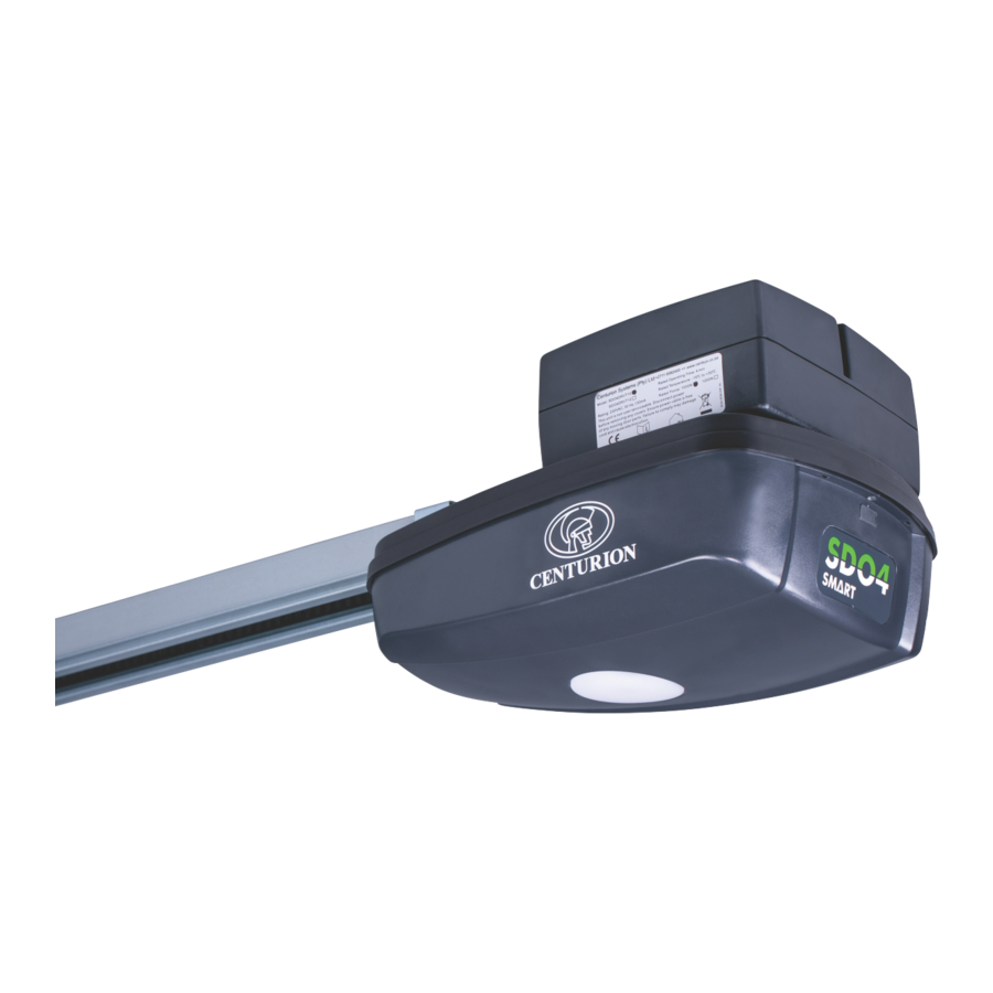
General Description
The SDO4 SMART has been designed to automate domestic garage doors safely, quietly and reliably.
The product's chain-driven system allows for whisper-quiet operation, while reliable battery backup ensures that the SDO4 SMART will continue working even during lengthy power outages.
In addition, the SDO4 SMART's built-in collision sensing circuitry makes it a very safe automation solution. Kits are available for both sectional and tip-up garage doors.
Technical Specifications
| T10 | T12 | |
| Input voltage | 230V AC @ 50/60Hz1 | |
| Motor voltage | 24V DC | |
| Motor power - | 80W DC | 100W DC |
| rated Motor supply | Battery supply 2x 12V 3.4Ah | Battery supply 2x 12V 3.4Ah |
| Max door width | 6500mm | |
| Max door area | 12 square metres | 15square metres |
| Maximum push/ pull force | 40kgf | 50kgf |
| Max holding capacity | 1000N | 1200N |
| Operations in standby mode | Up to 90 depending on the door size / weight / height / duration of power failure / condition of batteries | |
| Maximum operator travel speed 3 | 9m/min | |
| Door travel adjustment | Physical Endstops (Automatic limit set) | |
| Safety obstruction force system | Built-in menu | |
| Light | LED 2W | |
| Autoclose 2 | Menu Selectable | |
| Infrared safety beams | Menu Selectable. (Optional, but recommended) | |
| Radio receiver | Code-hopping 433MHz | |
| Receiver code storage capacity | 20x 4-Button NOVA transmitters | |
TABLE 1
1: Can operate off a solar supply, please consult Centurion Systems (Pty) Ltd for assistance.
2: Requires infrared safety beams to be fitted
3: Speed varies with load
Preparation of Site
Always recommend the fitment of additional safety equipment such as safety edges and safety beams, for additional protection against entrapment or other mechanical risks.
Ensure that no pipes or electrical cables are in the way of the intended installation.
Install the garage operator only if:
- It will not pose a hazard to the public
- The installation will meet all municipal and/or local authority requirements once completed
- The door mass and application is within the operator specifications
- There is a properly-earthed general purpose 220-240V AC power outlet that has been installed by a qualified electrical contractor
- All locks, ropes and / or securing mechanisms have been removed
- The ceiling structure is adequate enough to support the weight of the SDO4 SMART
- The garage door is in good working order, meaning:
- it opens freely;
- it is well-balanced;
![]() An improperly-balanced or malfunctioning garage door, could cause serious personal injury, death and / or property damage. Have a qualified person check and, if required, make repairs to the garage door before installing the SDO4 SMART.
An improperly-balanced or malfunctioning garage door, could cause serious personal injury, death and / or property damage. Have a qualified person check and, if required, make repairs to the garage door before installing the SDO4 SMART. - it does not move on its own if left in any position for more than 100mm;
- it can be installed to have sufficient clearance between moving parts when opening or closing to reduce the risk of personal injury and / or entrapment
 An improperly-balanced or malfunctioning garage door, could cause serious personal injury, death and / or property damage. Have a qualified person check and, if required, make repairs to the garage door before installing the SDO4 SMART.
 Attempting to repair the garage door without suitable technical qualifications, may result in severe personal injury, death, and / or property damage.
Identifying Garage Door Type
Identify the garage door type and then select the preferred installation method and assembly type that is best-suited to the application.
Sectional doors

- Use a 3247mm one-piece drive rail
- The standard 3247mm drive rail will lift a door up to 2440mm high. (An optional drive rail extension kit is available for doors over 2440mm high)
- The SDO4 SMART is supported by the drive rail hanger which is hung from the ceiling using appropriate hanging material
- The drive rail must be parallel with the ceiling as shown in Figure 1.
- The header bracket may be mounted on the front wall of the garage or on the ceiling adjacent to the front wall
Tip-Up doors

- Use a 2097mm one-piece drive rail
- The SDO4 SMART is supported by the drive rail hanger which is hung from the ceiling using appropriate hanging material
- The drive rail must be angled, so that the pivot points at each end of the connecting arm should be as close to horizontal as possible when the door is in the fully open position
- The header bracket may be mounted on the front wall of the garage or on the ceiling adjacent to the front wall
Operator Installation
Sectional Doors
Determine the highest arcing point of the garage door and mark this as a horizontal line on the header above the top edge of the garage door.
Close the garage door, and determine the garage door center line and mark a vertical line on the header above the door.

Mounting the Header Bracket
Place the header bracket on the wall as shown in Figure 4. Ensure that the bottom edge of the bracket is level, and no more than 50mm above the highest arcing point of the garage door. Mark the location of the four screw holes (Hole A, B, C and D[optional]).

Mounting the SDO4 SMART to the header bracket
Position the SDO4 SMART in place, with the open end of the drive rail facing the floor, and the tensioning bracket towards the garage door. You will need a second person to assist you with this.
Ensure that the tabs are level using a spirit level. Gently tap them with a hammer if they are not
Mounting the SDO4 SMART to the header bracket
Position the SDO4 SMART in place, with the open end of the drive rail facing the floor, and the tensioning bracket towards the garage door. You will need a second person to assist you with this.

Locate the long clevis pin through the holes and secure it into position with a supplied Circle Clip on the other end of the clevis pin.
Mounting the SDO4 SMART drive rail to the ceiling
Open the garage door, and gently rest the SDO4 SMART on top of the open door.
Find the centre line of the garage door, and mark it on the ceiling above the location of the drive rail hanger.

Use a two spirit levels long the length of the SDO4 SMART drive rail, and level out the SDO4 SMART, so that it is running parallel to the ceiling.
Place another spirit level perpendicular to the ceiling, and line it up with the center of the drive rail hanger bolt on the side of the drive rail hanger. Make a mark on the ceiling, and repeat this for the other side of the drive rail hanger.
Draw a line on the ceiling joining these two marks, perpendicular to the garage door center line made earlier.

 Ensure that the drive rail hanger bracket is positioned directly under a strong structural member of the ceiling. If it is not, move it along the drive rail to a suitable position before marking it off on the ceiling.
Align the punched angle iron centered onto the garage door centre line, and the perpendicular line running along the center of the horizontal face holes.
The horizontal face must face the back of the garage.
Secure the punched angle iron to the ceiling with suitable screws (depending on the structural member of the ceiling).

Level the SDO4 SMART again, and measure the length needed from the ceiling to the underside of the drive rail (Value X).

Remove the two drive rail hanger nuts from the bolts, and locate the two lengths of punched angle iron into position as shown in Figure 10. Secure them in position with the two drive rail hanger nuts.

 Using a spirit level, ensure that the SDO4 SMART is level on both the X-Axis and Z-Axis of the horizontal plain. If it is not, it may cause the motor to stress, or the drive rail to twist.

Mounting the towing bracket to the garage door
Close the garage door, and find its center line. Make a level mark perpendicular to the garage door center line, and in line with the top edge of the top roller of the garage door.
Center the towing bracket on the garage door center line and so that the center of the two holes on the protruding tabs are in line with the top edge of the top roller.

Secure the towing bracket into position using the three hexagonal head self-tapping screws supplied.
Fitting the bent towing arm to the towing bracket and straight towing arm.
Slot the bent towing arm between the two protruding tabs of the towing bracket, and align the holes. Note the orientation of the bent towing arm.
Locate the short clevis pin through the holes and secure it into position with a supplied Circle Clip on the other end of the clevis pin.
Slot the bent towing arm into the straight towing arm, and align the holes. If they do not align, move the carriage up or down the drive rail in order to align the holes of the bent and straight towing arms.

Once aligned, secure the towing arms into position using the two supplied hexagonal head flange nuts and bolts: one set through the bottom hole of the straight towing arm, and the other through the top hole of the bent towing arm.
Tip-up Doors
Determine the highest arcing point of the garage door and mark this as a horizontal line on the header above the top edge of the garage door.
Close the garage door, and determine the garage door center line and mark a vertical line on the header above the door.

Mounting the Header Bracket
Place the header bracket on the wall as shown in Figure 4. Ensure that the bottom edge of the bracket is level, and no more than 50mm above the highest arcing point of the garage door. Mark the location of the four screw holes (Hole A, B, C and D[optional]).

Mounting the drive rail more than 50mm above the highest arcing point of the garage door may cause the drive rail to flex excessively.
Place a fischer plug in each hole, followed by the header bracket.
Secure it in position with at least three coach screws (supplied) (13mm hexagonal head).
Ensure that the tabs are level using a spirit level. Gently tap them with a hammer if they are not
Mounting the SDO4 SMART to the header bracket
Position the SDO4 SMART in place, with the open end of the drive rail facing the floor, and the tensioning bracket towards the garage door. You will need a second person to assist you with this.

Locate the long clevis pin through the holes and secure it into position with a supplied Circle Clip on the other end of the clevis pin.
Mounting the SDO4 SMART drive rail to the ceiling
Open the garage door, and gently rest the SDO4 SMART on top of the open door.
Find the centre line of the garage door, and mark it on the ceiling above the location of the drive rail hanger.

Use a two spirit levels long the length of the SDO4 SMART drive rail, and level out the SDO4 SMART, so that it is running parallel to the ceiling.
Place another spirit level perpendicular to the ceiling, and line it up with the center of the drive rail hanger bolt on the side of the drive rail hanger. Make a mark on the ceiling, and repeat this for the other side of the drive rail hanger.
Draw a line on the ceiling joining these two marks, perpendicular to the garage door center line made earlier.

 Ensure that the drive rail hanger bracket is positioned directly under a strong structural member of the ceiling.
If it is not, move it along the drive rail to a suitable position before marking it off on the ceiling.
Align the punched angle iron centered onto the garage door centre line, and the perpendicular line running along the center of the horizontal face holes.
The horizontal face must face the back of the garage.
Secure the punched angle iron to the ceiling with suitable screws (depending on the structural member of the ceiling).

Position the SDO4 SMART again, and measure the length needed from the ceiling to the underside of the drive rail (Value X).

Remove the two drive rail hanger nuts from the bolts, and locate the two lengths of punched angle iron into position as shown in Figure 10. Secure them in position with the two drive rail hanger nuts.

Using a spirit level, ensure that the SDO4 SMART is level on both the X-Axis and Z-Axis of the horizontal plain. If it is not, it may cause the motor to stress, or the drive rail to twist.

Mounting the towing bracket to the garage door
Close the garage door, and find its center line. Make a level mark perpendicular to the garage door center line, and in line with the top edge of the top roller of the garage door.
Center the towing bracket on the garage door center line and so that the top edge of the towing bracket is as close to the top edge of the garage door as possible.

Secure the towing bracket into position using the three hexagonal head self-tapping screws supplied.
Fitting the bent towing arm to the towing bracket and straight towing arm.
Slot the bent towing arm between the two protruding tabs of the towing bracket, and align the holes. Note the orientation of the bent towing arm.
Locate the short clevis pin through the holes and secure it into position with a supplied Circle Clip on the other end of the clevis pin.
Slot the bent towing arm into the straight towing arm, and align the holes. If they do not align, move the carriage up or down the drive rail in order to align the holes of the bent and straight towing arms.

Once aligned, secure the towing arms into position using the two supplied hexagonal head flange nuts and bolts: one set through the bottom hole of the straight towing arm, and the other through the top hole of the bent towing arm.
Positioning the End-stops
The drive rail-mounted end-stops provide a one-to-one ratio between end stop movement and garage door movement, thereby ensuring 100% accuracy and ease of adjustment. Fully open and fully closed positions of the garage door can be easily adjusted by moving the ends-stops to the desired location in order to increase or decrease garage door travel.
Positioning the closing end-stop
- Ensure that the motor is disengaged
- Close the garage door fully
- Locate the closing end-stop within the drive rail - nearest to the front wall of the garage
- Position the end-stop 10mm away from the carriage, then tighten the two lock screws
Positioning the opening end-stop
- Ensure that the motor is disengaged
- Open the garage door fully
- Locate the opening end-stop within the drive rail - nearest to the back wall of the garage
- Position the end-stop 10mm away from the carriage, then tighten the two lock screws
- Re-engage the motor
Mounting the drive rail more than 50mm above the highest arcing point of the garage door may cause the drive rail to flex excessively.

Engaging and Disengaging
- TO DISENGAGE - pull down on the release handle until you hear a 'click'
- TO ENGAGE - Pull the release handle back towards the control head until you hear a 'click', and move the carriage until it engages with the chain bullet (Figure 3)

- Never attempt to open or close the garage door by pulling on the release handle. Doing so may result in SERIOUS PERSONAL INJURY and / or PROPERTY DAMAGE
- Always disengage the SDO4 SMART with the garage door in the fully closed position
Commissioning the System
- Scan the QR Code in Figure 8.
- Select the App Store applicable to the operating system being used, either Apple iStore or Android Google Play Store.
- Download and install the application.
![www.apple.com]()
![]()
Minimum Requirements:
- BLE-enabled mobile phone
- iPhone 5s and above
- iOS10
![play.google.com]()
Minimum Requirements:- BLE-enabled mobile phone
- Android 5.0 (Lollipop)


Alternatively, go directly to the app store of the operating system being used, and search for the app "MyCentsys Pro". Download and install the application onto the smartphone.

- Once installed, open the application.
- From the list of gate operators, select the operator that is applicable to this installation.
- Connect to the relevant gate operator.
- Use the app by following the prompts to configure the SDO4 SMART.
Connect with us on:
 facebook.com/centurionsystems
 YouTube.com/centurionsystems
 @askcenturion
 centurion.systems
Subscribe to the newsletter: www.centsys.com/subscribe
Call Centurion Systems (Pty) Ltd . South Africa Head Office: +27 11 699 2400
Call Technical Support: +27 11 699 2481 from 07h00 to 18h00 (UTC+2)
www.centsys.com.au
Call: 1300 CENTSYS (1300 236 879)
After Hours International Technical Support Call Centre
+27 11 699 2481 (16:00 to 02:00 - Australian Eastern Time)
E&OE Centurion Systems (Pty) Ltd reserves the right to change any product without prior notice
All product and brand names in this document that are accompanied by the ® symbol are registered trademarks in South Africa and/or other countries, in favour of Centurion Systems (Pty) Ltd, South Africa.
The CENTURION and CENTSYS logos, all product and brand names in this document that are accompanied by the TM symbol are trademarks of Centurion Systems (Pty) Ltd, in South Africa and other territories; all rights are reserved.
We invite you to contact us for further details.

Centurion Systems (Pty) Ltd
www.CentSys.com

Documents / Resources
References
![www.apple.com]() App Store - Apple
App Store - Apple![play.google.com]() Google Play
Google Play![www.centsys.com]() Home - Centurion Systems
Home - Centurion SystemsFacebook
![youtube.com]() CenturionSystems - YouTube
CenturionSystems - YouTube![www.centsys.com]() Sign-up for Our Newsletter - Centurion Systems
Sign-up for Our Newsletter - Centurion Systems![www.centsys.com.au]() CENTSYS D5-SMART - Centsys.com.au
CENTSYS D5-SMART - Centsys.com.au
Download manual
Here you can download full pdf version of manual, it may contain additional safety instructions, warranty information, FCC rules, etc.
Download CENTURION SYSTEMS SDO4 SMART - Garage Door Operators Quick Guide
Advertisement


Need help?
Do you have a question about the SDO4 SMART and is the answer not in the manual?
Questions and answers