Advertisement
Quick Links
Alarms & Remote Start
OEM-AL(RS)-CH7-[OL-MDB-ALL]-EN
NOTICE
The manufacturer will accept no responsability for any electrical
damage resulting from improper installation of this product, be that either
damage to the vehicle itself or to the installed device. This device must be in-
stalled by a certified technician. Please review the Installation Guide carefully
before beginning any work.
U.S. Patent No. 8,856,780
Automotive Data Solutions Inc. © 2016
INSTALL GUIDE
DOCUMENT NUMBER
29319
REVISION DATE
20160811
FIRMWARE
OEM-AL(RS)-CH7-[OL-MDB-ALL]
HARDWARE
OL-MDB-ALL
ACCESSORIES
OL-LOADER (REQUIRED)
BEFORE INSTALLATION
1- Connect module to computer
2- Login to Weblink account
3- Flash firmware to module (module is not preloaded with firmware)
4- Use accessories accordingly (accessories are sold separately)
Advertisement

Subscribe to Our Youtube Channel
Related Manuals for Omega Omegalink OL-MDB-ALL


Summary of Contents for Omega Omegalink OL-MDB-ALL
- Page 1 Alarms & Remote Start INSTALL GUIDE OEM-AL(RS)-CH7-[OL-MDB-ALL]-EN DOCUMENT NUMBER 29319 REVISION DATE 20160811 FIRMWARE OEM-AL(RS)-CH7-[OL-MDB-ALL] HARDWARE OL-MDB-ALL ACCESSORIES OL-LOADER (REQUIRED) NOTICE BEFORE INSTALLATION The manufacturer will accept no responsability for any electrical damage resulting from improper installation of this product, be that either 1- Connect module to computer damage to the vehicle itself or to the installed device.
- Page 2 PAGE 2 OF 26 VEHICLE LIST - 1 OF 1 • 20160811 DOC.: #29319 FEATURES NOTE I WARNING: All vehicle doors must be closed and locked prior to remote start sequence. 300 PTS AT 11-16 2 • • • • •...
-
Page 3: Box Contents
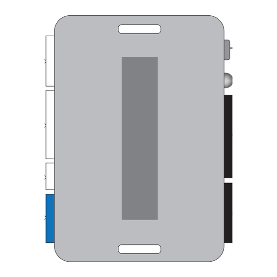
PAGE 3 OF 26 BOX CONTENTS - 1 OF 1 • 20160811 DOC.: #29319 BOX CONTENTS 6 PIN WHITE CONNECTOR 4 PIN BLACK CONNECTOR MODULE WHITE PROGRAMMING 10 PIN BLACK CONNECTOR BUTTON 7 PIN WHITE CONNECTOR LED 1 WHITE BLACK 3 PIN WHITE CONNECTOR DATA CABLE 1 WHITE... -
Page 4: Interior View
PAGE 4 OF 26 COMPONENT LOCATOR - 1 OF 1 • 20160811 DOC.: #29319 INTERIOR VIEW DRIVER SIDE VIEW PASSENGER SIDE VIEW U.S. Patent No. 8,856,780 Automotive Data Solutions Inc. © 2016 OEM-AL(RS)-CH7-[OL-MDB-ALL]-EN... - Page 5 PAGE 5 OF 26 TYPE 1 - WIRE CHART - 1 OF 1 • 20160811 DOC.: #29319 Black 06 pin 06 Red Push button Ground Black 06 pin 03 Black Push button Ignition Pink/White Driver kick panel Black 06 pin 04 Purple/Blue Push button Journey...
- Page 6 PAGE 6 OF 26 TYPE 1 - WIRING DIAGRAM - 1 OF 1 • 20160811 DOC.: #29319 MODULE PTS SWITCH PTS (+) - 04 IMO LIN - 05 E DATA GROUND (-) - 03 12V (+) - 06 7.5 A 01 GRAY/YELLOW (NC) GRAY/YELLOW (NC) 02 GRAY/RED (NC)
- Page 7 PAGE 7 OF 26 TYPE 2 - WIRE CHART - 1 OF 1 • 20160811 DOC.: #29319 Black 06 pin 06 Red Push button Ground Black 06 pin 03 Black Push button Ignition Pink/White Passenger kick panel Black 06 pin 04 Purple/Blue Push button IMO LIN...
- Page 8 PAGE 8 OF 26 TYPE 2 - WIRING DIAGRAM - 1 OF 1 • 20160811 DOC.: #29319 MODULE PTS SWITCH PTS (+) - 04 IMO LIN - 05 E DATA GROUND (-) - 03 12V (+) - 06 7.5 A 01 GRAY/YELLOW (NC) GRAY/YELLOW (NC) 02 GRAY/RED (NC)
- Page 9 PAGE 9 OF 26 TYPE 3 - WIRE CHART - 1 OF 1 • 20160811 DOC.: #29319 D2664A Black 06 pin Ignition connector Ground D2664A Black 06 pin Black Ignition connector D2664A Black 06 pin Purple/Brown Ignition connector 1500/ Ignition Gray 04 or 10 pin 02 or 10 Pink/Green Trailer pack connector, right of steering...
- Page 10 PAGE 10 OF 26 TYPE 3 - WIRING DIAGRAM - 1 OF 1 • 20160811 DOC.: #29319 MODULE PTS SWITCH PTS (+) - 04 IMO LIN - 05 E DATA GROUND (-) - 03 12V (+) - 06 7.5 A 01 GRAY/YELLOW (NC) GRAY/YELLOW (NC) 02 GRAY/RED (NC)
- Page 11 PAGE 11 OF 26 TYPE 4 - WIRE CHART - 1 OF 1 • 20160811 DOC.: #29319 D2664A Black 06 pin 06 Red Push button Ground D2664A Black 06 pin 03 Black Push button Ignition Gray 10 pin 02 Red/Green Driver kick panel Grand Cherokee/...
- Page 12 PAGE 12 OF 26 TYPE 4 - WIRING DIAGRAM - 1 OF 1 • 20160811 DOC.: #29319 MODULE PTS SWITCH PTS (+) - 04 IMO LIN - 05 E DATA GROUND (-) - 03 12V (+) - 06 7.5 A 01 GRAY/YELLOW (NC) GRAY/YELLOW (NC) 02 GRAY/RED (NC)
- Page 13 PAGE 13 OF 26 TYPE 5 - WIRE CHART - 1 OF 1 • 20160811 DOC.: #29319 Black 06 pin 06 Red Push button Ground Black 06 pin 03 Black Push button Ignition Gray 10 pin 02 Red/Green Driver kick panel Black 06 pin 04 Purple/Green...
- Page 14 PAGE 14 OF 26 TYPE 5 - WIRING DIAGRAM - 1 OF 1 • 20160811 DOC.: #29319 MODULE PTS SWITCH PTS (+) - 04 IMO LIN - 05 E DATA GROUND (-) - 03 12V (+) - 06 OBDII CONNECTOR 7.5 A 01 GRAY/YELLOW (NC) GRAY/YELLOW (NC)
- Page 15 PAGE 15 OF 26 TYPE 6 - WIRE CHART - 1 OF 1 • 20160811 DOC.: #29319 Black 06 pin 06 Red/LtGreen Push button Ground Black 06 pin 03 Black Push button Ignition Pink/White Passenger kick panel Black 06 pin 04 Purple/Blue Push button Challenger...
- Page 16 PAGE 16 OF 26 TYPE 6 - WIRING DIAGRAM - 1 OF 1 • 20160811 DOC.: #29319 MODULE PTS SWITCH PTS (+) - 04 IMO LIN - 05 E DATA GROUND (-) - 03 12V (+) - 06 7.5 A 01 GRAY/YELLOW (NC) GRAY/YELLOW (NC) 02 GRAY/RED (NC)
- Page 17 PAGE 17 OF 26 MODULE PROGRAMMING PROCEDURE - 1 OF 2 • 20160811 DOC.: #29319 Close driver door. Re-open driver door to wake Wait, LED will turn solid RED. Disconnect the BLACK 20-PIN connector. up data bus. Press Unlock on keyfob 1. Push start button once [1x] to OFF position.
- Page 18 PAGE 18 OF 26 MODULE PROGRAMMING PROCEDURE - 2 OF 2 • 20160811 DOC.: #29319 Push start button twice [2x] with keyfob 1 to STOP ACC ON START ON position. (No battery) ENGINE START STOP Wait, LED will turn solid GREEN for 2 seconds. Push start button once [1x] to OFF position.
- Page 19 PAGE 19 OF 26 VALET MODE PROGRAMMING PROCEDURE - 1 OF 1 • 20160811 DOC.: #29319 >> >> NOTE: In Valet Mode, the Remote starter is not To exit valet mode: repeat steps 1 to 5. functional. Keyless entry, Lock and Unlock will remain functional.
- Page 20 PAGE 20 OF 26 MODULE NAVIGATION PROCEDURE - 1 OF 1 • 20160811 DOC.: #29319 >> It is mandatory to exit the Module Navigation TO ACCESS THE OPTIONS: Press and hold To save and return to the OPTIONS: Press and at the end of this procedure.
- Page 21 PAGE 21 OF 26 MODULE NAVIGATION CHART - 1 OF 1 • 20160811 DOC.: #29319 MODULE NAVIGATION CHART: NOTES I Default settings are listed in bold. DISARM/UNLOCK BEFORE START II Make sure the option is covered on the vehicle before attempting to change the setting.
- Page 22 PAGE 22 OF 26 REMOTE STARTER ERROR CODES - 1 OF 1 • 20160811 DOC.: #29319 REMOTE STARTER ERROR CODES: NOTES Foot brake is ON. I WARNING: The following applies only when the parking lights are connected and supported by the system. Hood is open.
- Page 23 PAGE 23 OF 26 MODULE DIAGNOSTICS - 1 OF 1 • 20160811 DOC.: #29319 TEST MODULE Flashing RED Missing/wrong information from fi rmware or vehicle. Solid RED Module waiting for more vehicle information. Flashing GREEN Additional steps required to complete module programming. DURING PROGRAMMING Solid GREEN then OFF Module correctly programmed.
- Page 24 PAGE 24 OF 26 MODULE RESET PROCEDURE - 1 OF 1 • 20160811 DOC.: #29319 Disconnect all connectors from module except Reconnect all connectors. the BLACK 4-PIN connector. Disconnect the BLACK 4-PIN connector. Repeat programming procedure. >> PRESS AND HOLD programming button while Failure to follow procedure may result with a connecting the BLACK 4-PIN connector.
- Page 25 PAGE 25 OF 26 TAKEOVER PROCEDURE - PTS - 1 OF 1 • 20160811 DOC.: #29319 >> All OEM keyfobs must be at least 10 feet Take over procedure completed. away from the vehicle. All vehicle doors must be closed and locked prior to remote start sequence.
- Page 26 PAGE 26 OF 26 INSTALLATION CHECKLIST - 1 OF 1 • 20160811 DOC.: #29319 CHECKLIST WARNING: Vehicle engine will start many times. Test in a well ventilated area. Close all vehicle doors, hood and trunk. Press LOCK button three times [3x] rapidly on the OEM keyfob to remote start vehicle. Question 1: Does the vehicle remote start? YES: Go to next step.
Need help?
Do you have a question about the Omegalink OL-MDB-ALL and is the answer not in the manual?
Questions and answers