Table of Contents
Advertisement
Quick Links
Download this manual
See also:
Quick Manual
630 Komas Drive | Suite 200
Salt Lake City | UT 84108 | USA
P +1 801.582.5533 | F +1 801.582.1509
www.blackrockmicro.com
NeuroPort
Biopotential Signal
Processing System
User's Manual
Rev. 11.00 / LB-0175 – NeuroPort Biopotential Signal Processing System User's Manual
© 2018 Blackrock Microsystems, LLC
Advertisement
Table of Contents

Subscribe to Our Youtube Channel
Related Manuals for Blackrock Microsystems NeuroPort


Summary of Contents for Blackrock Microsystems NeuroPort
- Page 1 Salt Lake City | UT 84108 | USA P +1 801.582.5533 | F +1 801.582.1509 www.blackrockmicro.com NeuroPort Biopotential Signal Processing System User’s Manual Rev. 11.00 / LB-0175 – NeuroPort Biopotential Signal Processing System User’s Manual © 2018 Blackrock Microsystems, LLC...
-
Page 2: Table Of Contents
No Power to NeuroPort System ....................26 The NSP Stuck in Initializing .....................27 No Neural Activity on any Channels ..................27 Windows Compatibility Issues ....................27 Rev. 11.00 / LB-0175 – NeuroPort Biopotential Signal Processing System User’s Manual © 2018 Blackrock Microsystems, LLC... - Page 3 Figure 14 - Network Connections Window ................22 Figure 11 - Local Area Connections Properties .................22 Figure 126 - IPv4 Properties .....................22 Figure 137 – Central.exe Compatibility Mode ................28 Rev. 11.00 / LB-0175 – NeuroPort Biopotential Signal Processing System User’s Manual © 2018 Blackrock Microsystems, LLC...
-
Page 4: Introduction
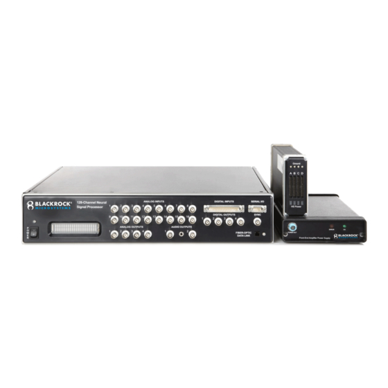
System Description The NeuroPort System is designed to record and process neural signals from up to 256 surface or penetrating electrodes in addition to auxiliary analog signals and digital experimental events. The system can perform real-time signal processing algorithms on neural signals, including noise cancellation, digital filtering, simultaneous extraction of spike and field potentials, and manual and automatic online spike sorting. -
Page 5: System Schematic
Front End Optional Cerebus NeurPort for System Testing Power Supply Software on Ethernet Software on Other PCs Switch Other PCs Figure 1–System Overview Rev. 11.00 / LB-0175 – NeuroPort Biopotential Signal Processing System User’s Manual © 2018 Blackrock Microsystems, LLC... -
Page 6: Symbols Of Contraindications, Warnings, Cautions
ISO 7000-2492 Batch ISO 7000-2493 Catalogue Number Contraindications The NeuroPort System is a recording system and should not be used in applications involving stimulation. Rev. 11.00 / LB-0175 – NeuroPort Biopotential Signal Processing System User’s Manual © 2018 Blackrock Microsystems, LLC... -
Page 7: Warnings
AC outlets using only the Blackrock provided power cable to reduce the risk of electrical shock. Do not use an adapter for ungrounded wall outlets. Do not connect the NeuroPort System to an outlet controlled by a wall switch, multiple socket-outlet or extension cord to avoid fires or other electrical hazards. -
Page 8: Specifications
Ordinary Equipment, not fluid resistant, IPX0 Protection Operating 10˚C to 35˚C, 5 to 85% R.H. (non-condensing) Environment Storage Environment -20˚C to 50˚C, 5 to 95% R.H. (non-condensing) Rev. 11.00 / LB-0175 – NeuroPort Biopotential Signal Processing System User’s Manual © 2018 Blackrock Microsystems, LLC... - Page 9 Guidance and manufacturer’s declaration electromagnetic immunity — The NeuroPort System is intended for use in the electromagnetic environment specified below. The customer or the user of the NeuroPort system should assure that it is used in such an environment. IEC 60601 test Compliance Electromagnetic environment —...
- Page 10 Recommended separation distances between portable and mobile RF communications equipment and the NeuroPort system The NeuroPort system is intended for use in an electromagnetic environment in which radiated RF disturbances are controlled. The customer or the user of the NeuroPort system can help prevent electromagnetic interference...
-
Page 11: Hardware
Amplifier Power Supply (APS) The APS consists of five analog and digital supply channels with monitoring, sequencing, and emergency shutdown controls. Figure 3–Amplifier Power Supply Rev. 11.00 / LB-0175 – NeuroPort Biopotential Signal Processing System User’s Manual © 2018 Blackrock Microsystems, LLC... -
Page 12: Neural Signal Processor (Nsp)
NSP and does not turn main power to the device ON/OFF. See rear panel for mains switch for mentioned part numbers. Rev. 11.00 / LB-0175 – NeuroPort Biopotential Signal Processing System User’s Manual © 2018 Blackrock Microsystems, LLC... -
Page 13: Figure 5-Digital In Pin Diagram
Figure 6–Serial I/O Pin Diagram Analog Outputs: Four ±5.0 V analog output BNC connectors can be used to send monitoring signals or stimulus waveforms to other connectors. Rev. 11.00 / LB-0175 – NeuroPort Biopotential Signal Processing System User’s Manual © 2018 Blackrock Microsystems, LLC... - Page 14 NSP neural signal inputs and front panel ports are scanned. It is active on the rising edge of the signal. Rev. 11.00 / LB-0175 – NeuroPort Biopotential Signal Processing System User’s Manual © 2018 Blackrock Microsystems, LLC...
-
Page 15: Figure 7-Nsp Back
NSP PN-4176 NSP PN-7530 NSP PN-9650 NSP PN-10411 Figure 7–NSP Back Rev. 11.00 / LB-0175 – NeuroPort Biopotential Signal Processing System User’s Manual © 2018 Blackrock Microsystems, LLC... - Page 16 Power switch used to turn main power ON/OFF to the NSP. Ensure this switch is in the ON position marked by the “I” on the switch. Rev. 11.00 / LB-0175 – NeuroPort Biopotential Signal Processing System User’s Manual © 2018 Blackrock Microsystems, LLC...
-
Page 17: Connectors, Cables, Etc
For longer connections, headstages from Blackrock Microsystems are recommended. Headstages allow microelectrodes with impedances up to 5-MΩ (at 1kHz), and cables up to 6 feet in length. Rev. 11.00 / LB-0175 – NeuroPort Biopotential Signal Processing System User’s Manual © 2018 Blackrock Microsystems, LLC... -
Page 18: Ics Connectors
The HSF-32 is built to work with Samtec (www.samtec.com) connectors and it is designed to mate with the ICS family of array holders from Blackrock Microsystems. If you are using an ICS array holder without a headstage, you will need to use a HBA-32 headstage bypass adaptor instead. -
Page 19: Neural Signal Amplifier Input
130 mA of combined current from the Amplifier. The ground pins on every bank are tied together. For best results, the Amplifier should be the central grounding point for electrical ground connections to the research subject. Rev. 11.00 / LB-0175 – NeuroPort Biopotential Signal Processing System User’s Manual © 2018 Blackrock Microsystems, LLC... -
Page 20: Cables
Note that the fiber-optic cable is very delicate. Please do not bend it (bend radius of 5.0 cm) or crush it! Figure 7–Fiber-optic Cable Figure 8–Crossover Cable Figure 9–Amplifier Power Supply (APS) Cable Rev. 11.00 / LB-0175 – NeuroPort Biopotential Signal Processing System User’s Manual © 2018 Blackrock Microsystems, LLC... -
Page 21: Digital Neural Signal Simulator (Dnss)
(spikes) as well as sine waves at different frequencies. It can be used to test a recording system in lieu of being connected to a subject. Figure 10–Digital Neural Signal Simulator Rev. 11.00 / LB-0175 – NeuroPort Biopotential Signal Processing System User’s Manual © 2018 Blackrock Microsystems, LLC... -
Page 22: Setup
Setup Hardware Setup Ethernet Card Setup Note: If you purchased the NeuroPort Host PC, the Ethernet card is pre-installed and configured in your PC. The supplied 1-Gbps PCI Ethernet card needs to be installed in a 64-bit PCI slot of the host PC and a crossover Ethernet cable (included) is needed to directly connect the host PC to the NSP. -
Page 23: Figure 14 - Network Connections Window
1-Gbps network switch with QoS feature. For other PCs connected using a network switch, IP addresses should increment, such as 192.168.137.2, 192.168.137.3, etc. Note: For your reference, the NSP’s IP address is 192.168.137.128. Rev. 11.00 / LB-0175 – NeuroPort Biopotential Signal Processing System User’s Manual © 2018 Blackrock Microsystems, LLC... -
Page 24: Hardware Specifications
+5.0 V, 500 mA analog –5.0 V, 500 mA analog +3.3 V, 300 mA digital +3.3 V, 500 mA digital +5.0 V, 300 mA digital Rev. 11.00 / LB-0175 – NeuroPort Biopotential Signal Processing System User’s Manual © 2018 Blackrock Microsystems, LLC... -
Page 25: Return Merchandise Authorization (Rma)
Return Merchandise Authorization (RMA) In the unlikely event that your NeuroPort system needs to be returned to Blackrock for repair or maintenance, do not send any equipment back without a Return Merchandise Authorization Number. An RMA number will be issued to you by a Blackrock representative. If you need to obtain an RMA number, you may contact a support representative at +1 (801) 582-5533 or via email support@blackrockmicro.com. -
Page 26: Complaints
Caution: Federal law restricts this device to sale by or on the order of a physician. This device complies with part 18 of the FCC rules Rev. 11.00 / LB-0175 – NeuroPort Biopotential Signal Processing System User’s Manual © 2018 Blackrock Microsystems, LLC... -
Page 27: Troubleshooting
NeuroPort. Verify the position of the power switch in the rear of the NeuroPort and make sure it is in the ON position. If the power switch is in the ON position, turn it to the off position then wait at least five seconds before turning the NSP back on. -
Page 28: The Nsp Stuck In Initializing
+1 (801) 582-5533 for assistance. No Neural Activity on any Channels If NeuroPort is turned on and running but there is no apparent activity on any of the channels from an implant or from the simulator, verify the following: Open Central.exe and verify that packets are being received from the NeuroPort system. -
Page 29: Figure 137 - Central.exe Compatibility Mode
Figure 137 – Central.exe Compatibility Mode Rev. 11.00 / LB-0175 – NeuroPort Biopotential Signal Processing System User’s Manual © 2018 Blackrock Microsystems, LLC...
Need help?
Do you have a question about the NeuroPort and is the answer not in the manual?
Questions and answers