Table of Contents
Advertisement
Quick Links
Advertisement
Table of Contents

Related Manuals for Blackrock Microsystems Cerebus NeuroPort


Summary of Contents for Blackrock Microsystems Cerebus NeuroPort
- Page 1 Manufacturer 630 Komas Drive Suite 200 Salt Lake City UT 84108 P +1 (801) 582-5533 F +1 (801) 582-1509 www.blackrockmicro.com Cerebus Instructions for Use Revision 16.00 / LB-0028 – Cerebus IFU – 2021/06 © 2021 Blackrock Microsystems, LLC...
-
Page 2: Table Of Contents
NSP Front Panel ................16 NSP Back Panel ................17 Quick Setup Guide .............. 19 Setting up the Digital Cerebus System .......... 19 Setting up the Ethernet Link ............19 Revision 16.00 / LB-0028 – Cerebus IFU © 2021 Blackrock Microsystems, LLC... - Page 3 The source status LED on Digital Hub is illuminating yellow or red..................... 23 The Central application fails to start..........23 Return Merchandise Authorization ........24 Warranty ................25 Support ................25 Complaints ..................25 Revision 16.00 / LB-0028 – Cerebus IFU © 2021 Blackrock Microsystems, LLC...
-
Page 4: What This Manual Covers
• Discrete video/graphics card • 2 gigabit Ethernet Ports A Host PC that is configured and tested by our engineers is available. Please contact sales@blackrockmicro.com for more information. Revision 16.00 / LB-0028 – Cerebus IFU © 2021 Blackrock Microsystems, LLC... -
Page 5: Setup Overview
Bio-potential signals may include Electrocorticography (ECoG), electroencephalography (EEG), electromyography (EMG), electrocardiography (ECG), electrooculography (EOC), action potentials (AP), and evoked potentials (EP). Revision 16.00 / LB-0028 – Cerebus IFU © 2021 Blackrock Microsystems, LLC... -
Page 6: Contraindications, Warnings, And Precautions
System and components must be electrically isolated for subject safety. • Note that the fiber-optic cable is very delicate. Do not bend it (bend radius of 5.0 cm) or crush it. Revision 16.00 / LB-0028 – Cerebus IFU © 2021 Blackrock Microsystems, LLC... -
Page 7: Symbols
5.2.8 Do Not Use if Indicates that a medical device Package is should not be used if the package Damaged has been damaged or opened. Revision 16.00 / LB-0028 – Cerebus IFU © 2021 Blackrock Microsystems, LLC... - Page 8 To identify any terminal which is Ground intended for connection to an external conductor for protection against electric shock in case of a fault, or the terminal of a protective earth (ground) electrode. Revision 16.00 / LB-0028 – Cerebus IFU © 2021 Blackrock Microsystems, LLC...
- Page 9 Part complying with IEC 60601-1. IEC 60101-1:2012 Medical Electrical Equipment: Basic Safety and Essential Performance Reference Symbol Title Meaning 0102 Danger of Danger of Electrostatic Discharge Electrostatic Discharge Revision 16.00 / LB-0028 – Cerebus IFU © 2021 Blackrock Microsystems, LLC...
-
Page 10: Specifications
Ingress Protection Ordinary Equipment, not fluid resistant, IPX0 Operating Environment 10˚C to 35˚C, 5 to 85% R.H. (non-condensing) Storage Environment -20˚C to 50˚C, 5 to 95% R.H. (non-condensing) Revision 16.00 / LB-0028 – Cerebus IFU © 2021 Blackrock Microsystems, LLC... -
Page 11: Digital Hub
Ingress Protection Ordinary Equipment, not fluid resistant, IP20 Operating Environment 10˚C to 40˚C, 5 to 95% R.H. (non-condensing) Storage Environment -20˚C to 50˚C, 5 to 100% R.H. (non-condensing) Revision 16.00 / LB-0028 – Cerebus IFU © 2021 Blackrock Microsystems, LLC... -
Page 12: Cerebus System Hardware
Digital Cerebus System. Simplified block diagram showing different components of the Digital Cerebus and their intended function within the system. Revision 16.00 / LB-0028 – Cerebus IFU © 2021 Blackrock Microsystems, LLC... -
Page 13: Digital Hub 128
If the input LED is not lit (such as shown in input 4 Fig 3-1) there is either no data being received or the HDMI cable is not plugged into the input slot. Revision 16.00 / LB-0028 – Cerebus IFU © 2021 Blackrock Microsystems, LLC... -
Page 14: Power
CerePlex Digital Headstages Blackrock Microsystems manufactures a range of different models of CerePlex digital headstages which are characterized by their low noise, light weight and small physical profile. These headstages are all compatible with the Digital Hub 128. -
Page 15: Neural Signal Processor (Nsp)
The hardware and architecture inside the NSP are both periodically optimized to improve the overall performance and reliability of the system. Blackrock Microsystems has so far released four different versions of the NSP mentioned below: •... -
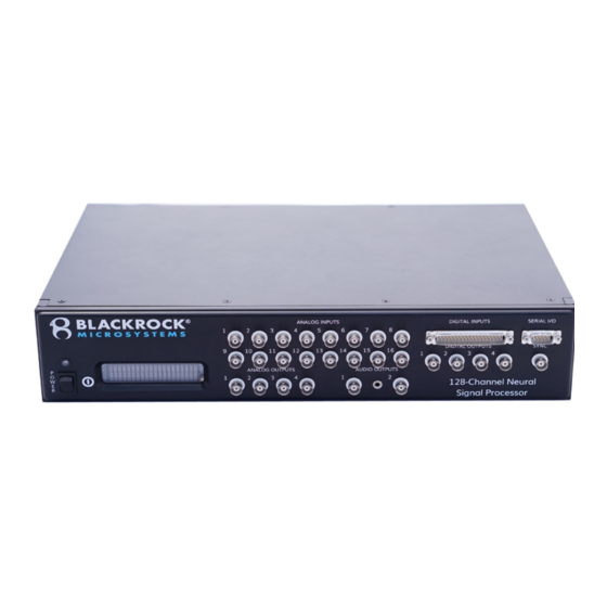
Page 16: Nsp Front Panel
Pin 2 is “Receive Data”, pin 3 is “Transmit Data”, and pin 5 is “Ground”. Serial I/O pin diagram. The configuration of the port is: Baud rate: 115200, Data bits: 8, Parity: none, Stop bits: 1, Flow control: disabled. Revision 16.00 / LB-0028 – Cerebus IFU © 2021 Blackrock Microsystems, LLC... -
Page 17: Nsp Back Panel
NSP models 1.5 and 1.0. The NSP 2.0 is equipped with an additional fiber optic input connector which enables the NSP 2.0 to communicate with more than one Digital Hub. Revision 16.00 / LB-0028 – Cerebus IFU © 2021 Blackrock Microsystems, LLC... - Page 18 NSP 2.0 Back panel view of different versions of NSP showing the adaptive Line Noise Cancellation plug (10), Synchronization Port (11), and the Fiber Optic input connector(s) (12). Revision 16.00 / LB-0028 – Cerebus IFU © 2021 Blackrock Microsystems, LLC...
-
Page 19: Quick Setup Guide
For other PCs connected using a network switch, IP addresses should increment, such as 192.168.137.2, 192.168.137.3, etc. The NSP’s IP address is currently fixed at 192.168.137.128. Revision 16.00 / LB-0028 – Cerebus IFU © 2021 Blackrock Microsystems, LLC... - Page 20 Setting the network properties on the Host PC. Revision 16.00 / LB-0028 – Cerebus IFU © 2021 Blackrock Microsystems, LLC...
-
Page 21: Troubleshooting
Panel. Click on start, type "uninstall a program". Click on "Uninstall a Program". Find Central Windows Suite, right click on it and click on Uninstall. 2. Download the latest Central Windows Suite from our website: http://blackrockmicro.com/technical-support/software-downloads/ Revision 16.00 / LB-0028 – Cerebus IFU © 2021 Blackrock Microsystems, LLC... -
Page 22: The Fiber Optic Led Indicator Is Illuminating Yellow Or Red
3. Also check for any visible damage to fiber optic cable or the connector. 4. In case none of above recommendations could solve the problem, contact support for additional instructions. Revision 16.00 / LB-0028 – Cerebus IFU © 2021 Blackrock Microsystems, LLC... -
Page 23: The Central Application Fails To Start
Firmware or Hardware issues on the NSP. Troubleshooting steps: 1. Check whether the NSP is powered on with the Firmware version visible on the and the ethernet settings. Revision 16.00 / LB-0028 – Cerebus IFU © 2021 Blackrock Microsystems, LLC... -
Page 24: Return Merchandise Authorization
Please address the package as follows: Blackrock Microsystems, LLC ATTN: RMA# 630 S. Komas Dr., Suite 200 Salt Lake City, UT 84108 USA Tel: +1 (801) 582-5533 Revision 16.00 / LB-0028 – Cerebus IFU © 2021 Blackrock Microsystems, LLC... -
Page 25: Warranty
Warranty Blackrock Microsystems (“Blackrock”) warrants that its products are free from defects in materials and manufacturing for a period of one year from the date of shipment. At its option, Blackrock will repair or replace any product that does not comply with this warranty.
Need help?
Do you have a question about the Cerebus NeuroPort and is the answer not in the manual?
Questions and answers