Table of Contents
Advertisement
Quick Links
Manufacturer
630 Komas Drive | Suite 200
Salt Lake City | UT 84108 | USA
P +1 (801) 582-5533 | F +1 (801) 582-1509
www.blackrockmicro.com
NeuroPort
Biopotential Signal
Processing System
Instructions for Use
Revision 1.00 / LB-1070 – NeuroPort Biopotential Signal Processing System IFU – 05/2021
© 2021 Blackrock Microsystems, LLC
Advertisement
Table of Contents

Subscribe to Our Youtube Channel
Related Manuals for Blackrock Microsystems NeuroPort


Summary of Contents for Blackrock Microsystems NeuroPort
- Page 1 Salt Lake City | UT 84108 | USA P +1 (801) 582-5533 | F +1 (801) 582-1509 www.blackrockmicro.com NeuroPort Biopotential Signal Processing System Instructions for Use Revision 1.00 / LB-1070 – NeuroPort Biopotential Signal Processing System IFU – 05/2021 © 2021 Blackrock Microsystems, LLC...
-
Page 2: Table Of Contents
Headstages ..................23 Digital Neural Signal Simulator (DNSS) ......... 23 Software ..................24 Central Main Window ..............24 Menu Bar ..................26 File ....................26 Revision 1.00 / LB-1070 – NeuroPort Biopotential Signal Processing System IFU © 2021 Blackrock Microsystems, LLC... - Page 3 Spike Sorting ................38 Tools Menu .................. 40 Adaptive Filtering ................. 40 N-Trode Groups ................41 Spike Panel ..................42 Spike Panel Settings ..............43 Revision 1.00 / LB-1070 – NeuroPort Biopotential Signal Processing System IFU © 2021 Blackrock Microsystems, LLC...
- Page 4 Spike Sorting .................. 59 Histogram Peak Count (Automatic) ..........59 Hoops (Manual) ................59 Manual PCA ................. 60 k-means PCA ................61 DBSCAN PCA ................62 Revision 1.00 / LB-1070 – NeuroPort Biopotential Signal Processing System IFU © 2021 Blackrock Microsystems, LLC...
- Page 5 Magnetic Resonance ..............70 Troubleshooting ................71 Return Merchandise Authorization (RMA) ........72 Warranty ..................73 Disposal ..................73 Support ..................74 Complaints ..................74 Revision 1.00 / LB-1070 – NeuroPort Biopotential Signal Processing System IFU © 2021 Blackrock Microsystems, LLC...
-
Page 6: What This Manual Covers
The NeuroPort Biopotential Signal Processing System is not a monitoring system. No physiological alarms are provided. The acquisition and display of biopotential signals is for the interpretation and use of the clinician. -
Page 7: Contraindications, Warnings, And Precautions
Do not use the NeuroPort System in the presence of flammable anesthetic agents. • Do not use the NeuroPort System for any use other than its listed intended use. • Avoid strong static discharges from sources like televisions or computer monitors because it can damage the electrical components of the system. -
Page 8: Symbols
Do Not Reuse Indicates a medical device that is intended for one use, or for use on a single patient during a single procedure. Revision 1.00 / LB-1070 – NeuroPort Biopotential Signal Processing System IFU © 2021 Blackrock Microsystems, LLC... - Page 9 Revision 1.00 / LB-1070 – NeuroPort Biopotential Signal Processing System IFU © 2021 Blackrock Microsystems, LLC...
- Page 10 Certain Prescription Device Labeling Requirements 2000-01-21 Symbol Title Meaning Prescription Caution: Federal (U.S.A.) law Only restricts this device to sale by or on the order of a physician. Revision 1.00 / LB-1070 – NeuroPort Biopotential Signal Processing System IFU © 2021 Blackrock Microsystems, LLC...
-
Page 11: Specifications
Type BF Applied Part Mode of Operation Continuous Water Ingress Protection Ordinary Equipment, not fluid resistant, IPX0 Operating Environment 10˚C to 35˚C, 5 to 85% R.H. (non-condensing) Revision 1.00 / LB-1070 – NeuroPort Biopotential Signal Processing System IFU © 2021 Blackrock Microsystems, LLC... -
Page 12: Front End Amplifier And Power Supply
Butterworth (high), 3 order Butterworth (low) 0.30 Hz to 7.5 kHz Power Supply to ±5.0 V output, up to 150 mA for powering optional headstages Headstages Revision 1.00 / LB-1070 – NeuroPort Biopotential Signal Processing System IFU © 2021 Blackrock Microsystems, LLC... -
Page 13: System Requirements
The diagrams below show an overview of the assembled system and subcomponents. Refer to the sections below for more detailed information on each component. Revision 1.00 / LB-1070 – NeuroPort Biopotential Signal Processing System IFU © 2021 Blackrock Microsystems, LLC... -
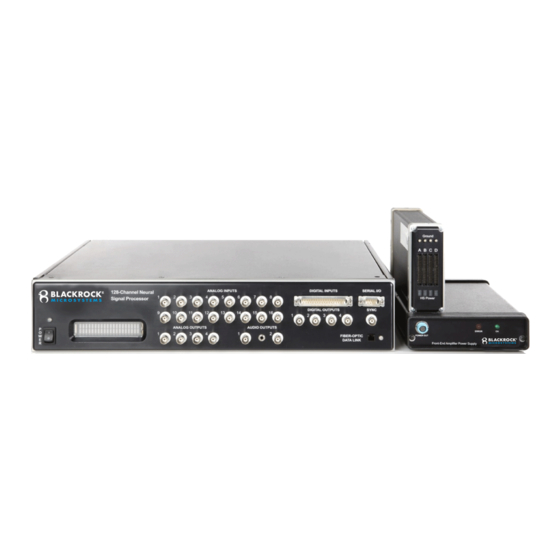
Page 14: Neuroport System
NeuroPort System Revision 1.00 / LB-1070 – NeuroPort Biopotential Signal Processing System IFU © 2021 Blackrock Microsystems, LLC... - Page 15 Guidance and manufacturer’s declaration electromagnetic immunity — The NeuroPort System is intended for use in the electromagnetic environment specified below. The customer or the user of the NeuroPort system should assure that it is used in such an environment. IEC 60601 test...
- Page 16 Recommended separation distances between portable and mobile RF communications equipment and the NeuroPort system The NeuroPort system is intended for use in an electromagnetic environment in which radiated RF disturbances are controlled. The customer or the user of the NeuroPort system can help prevent electromagnetic interference...
-
Page 17: Hardware
Ω. The coupling of each input channel can be manually selected in the software. By default, channels 1-8 are AC-coupled and channels 9-16 are DC-coupled. Revision 1.00 / LB-1070 – NeuroPort Biopotential Signal Processing System IFU © 2021 Blackrock Microsystems, LLC... - Page 18 A synchronization pulse can be set as an optional line to inform external equipment when the NSP neural signal inputs and front panel ports are scanned. It is active on the rising edge of the signal. Revision 1.00 / LB-1070 – NeuroPort Biopotential Signal Processing System IFU © 2021 Blackrock Microsystems, LLC...
- Page 19 NSP PN-4176 NSP PN-7530 NSP PN-9650 NSP PN-10411 Figure 4–NSP Back Revision 1.00 / LB-1070 – NeuroPort Biopotential Signal Processing System IFU © 2021 Blackrock Microsystems, LLC...
-
Page 20: Neural Signal Amplifier
At a later stage, digital filtering will allow these two signals to be separated and recorded in different data files. Figure 5–Neural Signal Amplifier Revision 1.00 / LB-1070 – NeuroPort Biopotential Signal Processing System IFU © 2021 Blackrock Microsystems, LLC... -
Page 21: Amplifier Power Supply (Aps)
Amplifier Power Supply (APS) The APS consists of five analog and digital supply channels with monitoring, sequencing, and emergency shutdown controls. Figure 7–Amplifier Power Supply Revision 1.00 / LB-1070 – NeuroPort Biopotential Signal Processing System IFU © 2021 Blackrock Microsystems, LLC... -
Page 22: Cables
Neural Signal Processor to the recording computer, and the Front End Amplifier Power Supply cable is used to connect the Front End Amplifier to its power supply. The Digital NeuroPort System does not include the front end amplifier power supply cable. Figure 8–Fiber-optic Cable Figure 9–Crossover Cable... -
Page 23: Accessories
(spikes) as well as sine waves at different frequencies. It can be used to test a recording system in lieu of being connected to a subject. Figure 11–Digital Neural Signal Simulator Revision 1.00 / LB-1070 – NeuroPort Biopotential Signal Processing System IFU © 2021 Blackrock Microsystems, LLC... -
Page 24: Software
Central can be run from the desktop shortcut, the Start menu shortcut, or by navigating to the executable in the Blackrock Microsystems directory in Program Files. The Central main application connects to a Blackrock Neural Signal Processor to configure hardware channels and acquire data. - Page 25 System Load displays the volume of incoming data from the Neural Signal Processor. Revision 1.00 / LB-1070 – NeuroPort Biopotential Signal Processing System IFU © 2021 Blackrock Microsystems, LLC...
-
Page 26: Menu Bar
Tools The Tools menu contains functions regarding thresholding, spike-sorting and general application settings. The spike sorting options are discussed on Page 38. Revision 1.00 / LB-1070 – NeuroPort Biopotential Signal Processing System IFU © 2021 Blackrock Microsystems, LLC... -
Page 27: Options
Log PCA coordinates on ‘Record’: Will log the spike-sorting model only when recording begins. Revision 1.00 / LB-1070 – NeuroPort Biopotential Signal Processing System IFU © 2021 Blackrock Microsystems, LLC... -
Page 28: Windows
System Summary: Displays average number of units per channel if using automatic histogram peak-count sorting. Options to disable cross talking channels and launch the impedance tester are also found here. Revision 1.00 / LB-1070 – NeuroPort Biopotential Signal Processing System IFU © 2021 Blackrock Microsystems, LLC... -
Page 29: Hardware Configuration
Once all channels of interest are selected, right-click then select properties, or click the Channel Properties icon in the toolbar. Each channel type, and their respective options are described below. Revision 1.00 / LB-1070 – NeuroPort Biopotential Signal Processing System IFU © 2021 Blackrock Microsystems, LLC... -
Page 30: Front End Analog Inputs
Graphical Chooser: Visualize the continuous signal filter in place. Sampling Rate: Select the sampling rate of data acquisition. Channel Chooser: Select the sampling rate for data acquisition on any channel. Revision 1.00 / LB-1070 – NeuroPort Biopotential Signal Processing System IFU © 2021 Blackrock Microsystems, LLC... - Page 31 Sorting Algorithm: Set the sorting algorithm for a channel as described in Spike Sorting on Page 38. Enable Amplitude Rejection: Rejects waveforms exceeding a specified amplitude. Upper/Lower Limit (uV): Voltage limits for amplitude rejection. Revision 1.00 / LB-1070 – NeuroPort Biopotential Signal Processing System IFU © 2021 Blackrock Microsystems, LLC...
-
Page 32: Analog Output
5 V output signal containing only identified spike events. Input Range: Input voltage range displayed for reference. Output Range: Output voltage range displayed for reference. Revision 1.00 / LB-1070 – NeuroPort Biopotential Signal Processing System IFU © 2021 Blackrock Microsystems, LLC... -
Page 33: Analog Output: Sine Waveform
Duration (ms): Phase duration. Repeats: Indicates the number of times to repeat the waveform once triggered. A value of 0 will repeat the waveform indefinitely. Revision 1.00 / LB-1070 – NeuroPort Biopotential Signal Processing System IFU © 2021 Blackrock Microsystems, LLC... -
Page 34: Analog Output: Triggering
Digital Inputs may take on the functions listed below. 16-bit on word strobe: Reads 16 bits on the rising edge of the strobe pin. Revision 1.00 / LB-1070 – NeuroPort Biopotential Signal Processing System IFU © 2021 Blackrock Microsystems, LLC... -
Page 35: Digital Output
Panel, Single Neural Channel, or Raster Plot view is used as the monitor input. Source: Select which channel to monitor. Monitored Units: Select which spike unit classifications to trigger on. Revision 1.00 / LB-1070 – NeuroPort Biopotential Signal Processing System IFU © 2021 Blackrock Microsystems, LLC... -
Page 36: Digital Output: Timed
Serial communication parameters cannot be changed. Figure 23–Serial I/O Revision 1.00 / LB-1070 – NeuroPort Biopotential Signal Processing System IFU © 2021 Blackrock Microsystems, LLC... -
Page 37: Global Settings
Single Neural Channel when the Raw/LNC button is checked. Filters This window displays the details of a selected digital filter in a bode plot and key numerical parameters. Figure 24–Filter Properties Display Revision 1.00 / LB-1070 – NeuroPort Biopotential Signal Processing System IFU © 2021 Blackrock Microsystems, LLC... -
Page 38: Auto Thresholding
Outlier Removal: Removes outliers exceeding this number of standard deviations from the centroid of each group. Minimum Group Size: Remove any groups that have fewer than this number of spikes. Revision 1.00 / LB-1070 – NeuroPort Biopotential Signal Processing System IFU © 2021 Blackrock Microsystems, LLC... - Page 39 Artifact Rejection Maximum Simultaneous Channels: If more than the maximum number of channels contain simultaneous spike events, the events are all rejected. Revision 1.00 / LB-1070 – NeuroPort Biopotential Signal Processing System IFU © 2021 Blackrock Microsystems, LLC...
-
Page 40: Tools Menu
The Adaptive Filtering feature can use a noise signal as a reference for neural signal channels. Adaptive Filtering: Choose one or two channels to reference. Revision 1.00 / LB-1070 – NeuroPort Biopotential Signal Processing System IFU © 2021 Blackrock Microsystems, LLC... -
Page 41: N-Trode Groups
N-Trode as a single entity. To define N-Trode groups, open a group and add channels to it with the arrow buttons or by double clicking. Figure 28–N-Trode Properties Revision 1.00 / LB-1070 – NeuroPort Biopotential Signal Processing System IFU © 2021 Blackrock Microsystems, LLC... -
Page 42: Spike Panel
If spike-sorting rules are defined, the spikes belonging to different units will be displayed in different colors. Figure 29–Spike Panel Revision 1.00 / LB-1070 – NeuroPort Biopotential Signal Processing System IFU © 2021 Blackrock Microsystems, LLC... -
Page 43: Spike Panel Settings
Continuous traces and comments can also be shown on the plot. Figure 30–Raster Plot Revision 1.00 / LB-1070 – NeuroPort Biopotential Signal Processing System IFU © 2021 Blackrock Microsystems, LLC... -
Page 44: Tool Bar
Broadcast Channel Selections: Duplicate channel selection on other instances of Central running on computers connected to the Ethernet switch. Level of Criticality: Display the current application load. Revision 1.00 / LB-1070 – NeuroPort Biopotential Signal Processing System IFU © 2021 Blackrock Microsystems, LLC... -
Page 45: Single Neural Channel
View Classification: Toggle the Online Classification Display. Broadcast Channel Selections: Duplicates channel selection on other instances of Central running on computers connected to the Ethernet switch. Revision 1.00 / LB-1070 – NeuroPort Biopotential Signal Processing System IFU © 2021 Blackrock Microsystems, LLC... -
Page 46: Spike Display
You may also change the diameter of the ellipse. Once the ellipse is placed around a cluster of points. The word “Overridden” will appear next to the sorted unit. Revision 1.00 / LB-1070 – NeuroPort Biopotential Signal Processing System IFU © 2021 Blackrock Microsystems, LLC... -
Page 47: File Storage
Resume file recording through the digital input port, or the serial I/O port. Click the Setup button below the remote recording check box to set user-defined hex Revision 1.00 / LB-1070 – NeuroPort Biopotential Signal Processing System IFU © 2021 Blackrock Microsystems, LLC... -
Page 48: 2.X Interface
Split File Interval: Enter either a duration or file size limit for each file segment. If file size is specified, click on “Calculate Time” to automatically populate the “Estimated Time” field. Revision 1.00 / LB-1070 – NeuroPort Biopotential Signal Processing System IFU © 2021 Blackrock Microsystems, LLC... -
Page 49: Digital Oscilloscope
Figure 35–Trace Amplitude given range. Time/Frequency selection: Set the oscilloscope into time or frequency mode. Revision 1.00 / LB-1070 – NeuroPort Biopotential Signal Processing System IFU © 2021 Blackrock Microsystems, LLC... -
Page 50: Trigger Type
Set a negative value to push the trigger point to the right. Revision 1.00 / LB-1070 – NeuroPort Biopotential Signal Processing System IFU © 2021 Blackrock Microsystems, LLC... -
Page 51: Digital Filter Editor
Bode Plot and the Nyquist Plot of the designed filter are displayed. Once the filter parameters are set, click on Save to save the digital filter. Figure 36–Digital Filter Editor Revision 1.00 / LB-1070 – NeuroPort Biopotential Signal Processing System IFU © 2021 Blackrock Microsystems, LLC... -
Page 52: Activity Map
Load Map File: Load a map file to change the orientation of the display. Default Map File: Return to the default 16x8 grid map file. Revision 1.00 / LB-1070 – NeuroPort Biopotential Signal Processing System IFU © 2021 Blackrock Microsystems, LLC... -
Page 53: Signal-To-Noise Ratio
In the example below the SNR for elec11 unit 3 is 9.50 meaning that the signal is 9.5 times bigger than the noise. Figure 38–Signal to Noise Ratio Revision 1.00 / LB-1070 – NeuroPort Biopotential Signal Processing System IFU © 2021 Blackrock Microsystems, LLC... -
Page 54: Neural Modulation
Modulation Index is the variance of the histogram entries and covers a range of 0 to 12.0. A range of 2 to 5 is considered normal when recording neural signals. Figure 39–Neural Modulation Revision 1.00 / LB-1070 – NeuroPort Biopotential Signal Processing System IFU © 2021 Blackrock Microsystems, LLC... -
Page 55: Impedance Tester
Special equipment may be required for impedance measurements. Contact Blackrock Microsystems sales at sales@blackrockmicro.com for more information. Figure 40–Auto Impedance Revision 1.00 / LB-1070 – NeuroPort Biopotential Signal Processing System IFU © 2021 Blackrock Microsystems, LLC... -
Page 56: Crosstalk
Yellow: Possible cross correlation found. Examine signals closely to determine best use. Red: High levels of cross correlation found. Consider removing these channels from recordings. Figure 41–Crosstalk Revision 1.00 / LB-1070 – NeuroPort Biopotential Signal Processing System IFU © 2021 Blackrock Microsystems, LLC... -
Page 57: N-Trode
Note: Spike sorting occurs on the N-Trode as a single entity. This causes neural events on all N-Trode channels to be subject to refractory periods caused by a neural event detected on any N-Trode channel. Figure 42–N-Trode Utility Revision 1.00 / LB-1070 – NeuroPort Biopotential Signal Processing System IFU © 2021 Blackrock Microsystems, LLC... -
Page 58: Spike Display
A Neural Signal Processor does not need to be connected to the PC to use this utility. Figure 43–nPlay Server Revision 1.00 / LB-1070 – NeuroPort Biopotential Signal Processing System IFU © 2021 Blackrock Microsystems, LLC... -
Page 59: Spike Sorting
4. Open Single Neural Channel and select the desired channel. 5. Make sure the view classification icon is pressed down so you can see the units window. Revision 1.00 / LB-1070 – NeuroPort Biopotential Signal Processing System IFU © 2021 Blackrock Microsystems, LLC... -
Page 60: Manual Pca
PCA basis vectors. The time required to record 250 waveforms will depend on your spike rates and may take several minutes. You can Revision 1.00 / LB-1070 – NeuroPort Biopotential Signal Processing System IFU © 2021 Blackrock Microsystems, LLC... -
Page 61: K-Means Pca
6. Make sure the unit icon is pressed down so you can see the units window. 7. Click on the Feature tab. Figure 47–PCA Basis Waveforms Revision 1.00 / LB-1070 – NeuroPort Biopotential Signal Processing System IFU © 2021 Blackrock Microsystems, LLC... -
Page 62: Dbscan Pca
3. Right click the channel icon and select properties. 4. Select one or two channel operation. 5. Select the analog inputs used for the noise sources as reference channels. Revision 1.00 / LB-1070 – NeuroPort Biopotential Signal Processing System IFU © 2021 Blackrock Microsystems, LLC... -
Page 63: Create Custom Filters
Number using channel ID: Number with the channel ID value going from 1 to 128. iii. Use terminal numbering: Number with the pin and bank value of the channel location on the front-end amplifier. Revision 1.00 / LB-1070 – NeuroPort Biopotential Signal Processing System IFU © 2021 Blackrock Microsystems, LLC... -
Page 64: Remotely Control Data Recording
You can set the trigger level by entering a voltage value in the field or by sliding the trigger line up and down on the display. Revision 1.00 / LB-1070 – NeuroPort Biopotential Signal Processing System IFU © 2021 Blackrock Microsystems, LLC... -
Page 65: Configure Raster Plot
Change the font size for channel labels to be easily read. 9. For an explanation of further Raster Plot functionality see Page 43. Revision 1.00 / LB-1070 – NeuroPort Biopotential Signal Processing System IFU © 2021 Blackrock Microsystems, LLC... -
Page 66: Change Electrode Map (Create A Map File)
8 Channel NSP mapping 4 elec08 8 elec07 3 elec06 6 elec05 5 elec01 2 elec02 7 elec03 1 elec04 Figure 50–Sample CMP File Revision 1.00 / LB-1070 – NeuroPort Biopotential Signal Processing System IFU © 2021 Blackrock Microsystems, LLC... - Page 67 The first line after the last // line is the name of the map file as referenced in the apps and will also be ignored. Revision 1.00 / LB-1070 – NeuroPort Biopotential Signal Processing System IFU © 2021 Blackrock Microsystems, LLC...
-
Page 68: Setup
Refrain from installing any additional software or connecting the PC to the internet. Setting up the Ethernet Connection Note: If you purchased the NeuroPort Host PC, the Ethernet card is pre-installed and configured in your PC. 1. Once installed, the card needs to be configured to connect to the NSP. - Page 69 1-Gbps network switch with QoS feature. For other PCs connected using a network switch, IP addresses should increment, such as 192.168.137.2, 192.168.137.3, etc. Note: For your reference, the NSP’s IP address is 192.168.137.128. Revision 1.00 / LB-1070 – NeuroPort Biopotential Signal Processing System IFU © 2021 Blackrock Microsystems, LLC...
-
Page 70: Cleaning, Maintenance, And Disposal
Return to a recycling point for electric and electronic devices. Magnetic Resonance The NeuroPort System has not been evaluated for safety and compatibility in the MR environment. The NeuroPort System has not been tested for heating, migration, or image artifact in the MR environment. For this reason, the device is not considered safe to use in an MR environment. -
Page 71: Troubleshooting
Failed No Data Powered Off Device connected. Check that the ethernet switch is powered on if it is being used. Revision 1.00 / LB-1070 – NeuroPort Biopotential Signal Processing System IFU © 2021 Blackrock Microsystems, LLC... -
Page 72: Return Merchandise Authorization (Rma)
Return Merchandise Authorization (RMA) In the unlikely event that your NeuroPort system needs to be returned to Blackrock for repair or maintenance, do not send any equipment back without a Return Merchandise Authorization Number. An RMA number will be issued to you by a Blackrock representative. If you need to obtain an RMA number, you may contact a support representative at +1 (801) 582-5533 or via email support@blackrockmicro.com. -
Page 73: Warranty
Warranty Blackrock Microsystems (“Blackrock”) warrants its products are free from defects in materials and manufacturing for a period of one-year from the date of shipment. At its option, Blackrock will repair or replace any product that does not comply with this warranty. This warranty is voided by: (1) any modification or attempted modification to the product done by anyone other than an authorized Blackrock employee;... -
Page 74: Support
Caution: Federal law restricts this device to sale by or on the order of a physician. This device complies with part 18 of the FCC rules Revision 1.00 / LB-1070 – NeuroPort Biopotential Signal Processing System IFU © 2021 Blackrock Microsystems, LLC...
Need help?
Do you have a question about the NeuroPort and is the answer not in the manual?
Questions and answers