
Subscribe to Our Youtube Channel
Related Manuals for Trane SINTESIS ADVANTAGE CGAF


Summary of Contents for Trane SINTESIS ADVANTAGE CGAF
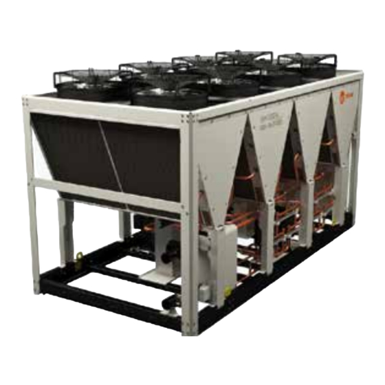
- Page 1 Installation Operation Maintenance CGAF Air-Cooled Scroll Chillers CXAF Air to Water Scroll Heat Pumps 260 - 710 kW R-410A – R-454B Refrigerant CG-SVX039F-GB May 2024 Confidential and proprietary Trane information Original instructions...
-
Page 2: Table Of Contents
Controls/Tracer TD-7 Operator Interface �����������������������������������������������������������������78 Unit Start-Up Procedures ������������������������������������������������������������������������������������������81 Periodic Maintenance ������������������������������������������������������������������������������������������������83 Compressor Service Information �����������������������������������������������������������������������������86 Condenser Coils MCHE Maintenance ����������������������������������������������������������������������88 Integrated Pump Maintenance ���������������������������������������������������������������������������������90 BPHE Evaporator Maintenance ��������������������������������������������������������������������������������91 Log Check Sheet ��������������������������������������������������������������������������������������������������������92 Recommended Service Routine Frequencies ���������������������������������������������������������93 Additional Services����������������������������������������������������������������������������������������������������94 ©2024 Trane CG-SVX039F-GB... -
Page 3: General Information
• Specify any visible damage on the delivery note� minor or moderate injury� It may also be used to alert against unsafe practices or for equipment or • Notify the local TRANE sales office at the same time� property-damage-only accidents�... - Page 4 If the user does not conform to the rules of this manual, it may entail the cancellation of warranty and liabilities by the manufacturer� Startup MUST be performed by Trane, or an authorized agent of Trane, to VALIDATE this WARRANTY�...
-
Page 5: Unit Description
The chilled water inlet and outlet openings are covered for shipment� Units feature Trane’s exclusive Tracer ® UC800/ Symbio™ 800 Control logic and controls� It monitors the control variables that govern the operation of the unit� Control logic can correct... -
Page 6: Unit Model Number Description
Unit Model Number Description Digit 1, 2, 3, 4 – Unit Model Digit 20 – Evaporator Configurations CGAF = Air-Cooled Scroll – Chiller B = Brazed plate heat exchanger CXAF = Air-Cooled Scroll – Heat Pump T = Shell and Tube heat exchanger Digit 5-7 –... - Page 7 Unit Model Number Description Digit 31 – Flow Switch V = Portuguese X = None Z = Slovenian F = Field installed flow switch 2 = Romanian 3 = Serbian Digit 32 – Electrical Panel Protection 4 = Slovak X = Enclosure with deadfront protection 5 = Croatian 1 = Enclosure with IP 20 internal protection 6 = Hungarian...
-
Page 8: Pre-Installation
This switch. checklist is intended to be a guide for the Trane 19. With water circulating through the system, technician just prior to unit ‘start-up’� Many of the adjust water flow and check water pressure recommended checks and actions could expose drop through evaporator. - Page 9 If the chiller is to be stored for more than one 9.5 bar (R-454B) at 10°C}, call a qualified service month prior to installation, observe the following organization and the appropriate Trane sales office. precautions: Note: If the unit is stored before servicing near •...
-
Page 10: General Data
General Data Table 1 – General data CGAF 090-190 standard efficiency CGAF CGAF CGAF CGAF CGAF CGAF CGAF CGAF CGAF Net Cooling Capacity For R-410A (1) (kW) 324.1 355.2 397.8 441.0 491.0 524.9 567.8 632.5 676.1 Net Total Power input For R-410A (1) (kW) 103.0 117.3 135.1... - Page 11 General Data Table 1 – General data CGAF 090-190 standard efficiency (continued) CGAF CGAF CGAF CGAF CGAF CGAF CGAF CGAF CGAF Single pump - High head pressure option Max available Head Pressure (kPa) Motor Power (kW) Rated Amps 20.8 20.8 20.8 20.8 Twin pump - Standard head pressure option...
- Page 12 General Data Table 1 – General data CGAF 090-190 standard efficiency (continued) CGAF CGAF CGAF CGAF CGAF CGAF CGAF CGAF CGAF Weights Shipping Weight (3) (kg) 2085 2200 2260 2325 2825 3005 3070 3435 3505 Option Additional shipping weight Single pump - Standard head (kg) pressure Single pump - High head pressure (kg)
- Page 13 General Data Table 2 – General data CGAF 080-190 high efficiency CGAF CGAF CGAF CGAF CGAF CGAF CGAF CGAF CGAF CGAF Net Cooling Capacity For R-410A (1) (kW) 293.5 334.6 372.0 418.9 464.2 514.2 548.2 589.5 646.6 689.8 Net Total Power input For R-410A (1) (kW) 89.0 100.0 113.0...
- Page 14 General Data Table 2 – General data CGAF 080-190 high efficiency (continued) CGAF CGAF CGAF CGAF CGAF CGAF CGAF CGAF CGAF CGAF Hydraulic Module Components Single pump - Standard head pressure option Max available Head Pressure (kPa) Motor Power (kW) 11.0 11.0 11.0...
- Page 15 General Data Table 2 – General data CGAF 080-190 high efficiency (continued) CGAF CGAF CGAF CGAF CGAF CGAF CGAF CGAF CGAF CGAF Weights Shipping Weight (3) (kg) 2015 2410 2540 2615 2675 3200 3375 3415 3785 3850 Option Additional shipping weight Single pump - Standard head (kg) pressure...
- Page 16 General Data Table 3 – General data CGAF 080-190 extra efficiency CGAF CGAF CGAF CGAF CGAF CGAF CGAF CGAF CGAF CGAF Net Cooling Capacity For (kW) 297.5 337.4 376.4 426.6 477.2 522.5 561.5 608.0 660.3 708.8 R-410A (1) Net Total Power input For (kW) 87.1 98.5...
- Page 17 General Data Table 3 – General data CGAF 080-190 extra efficiency (continued) CGAF CGAF CGAF CGAF CGAF CGAF CGAF CGAF CGAF CGAF Twin pump - Standard head pressure option Max available Head (kPa) Pressure Motor Power (kW) Rated Amps 14.4 14.4 14.4 14.4...
- Page 18 General Data Table 3 – General data CGAF 080-190 extra efficiency (continued) CGAF CGAF CGAF CGAF CGAF CGAF CGAF CGAF CGAF CGAF Weights (6) Shipping Weight (3) (kg) 2015 2410 2540 2615 2675 3200 3375 3415 3785 3850 Option Additional shipping weight Single pump - Standard (kg) head pressure...
- Page 19 General Data Table 4 – General data CGAF 090-150 standard efficiency – Shell and Tube (R-410A) CGAF CGAF CGAF CGAF CGAF CGAF Net Cooling Capacity (1) (kW) 322.4 352.4 390.9 425.0 494.5 522.5 Net Total Power input in cooling (1) (kW) 101.8 116.1...
- Page 20 General Data Table 4 – General data CGAF 090-150 standard efficiency – Shell and Tube (R-410A) (continued) CGAF CGAF CGAF CGAF CGAF CGAF Twin pump - Standard head pressure option Max available Head Pressure (kPa) Motor Power (kW) Rated Amps 14.4 14.4 14.4...
- Page 21 General Data Table 4 – General data CGAF 090-150 standard efficiency – Shell and Tube (R-410A) (continued) CGAF CGAF CGAF CGAF CGAF CGAF Weights (6) Shipping Weight (6) (kg) 2267 2366 2414 2447 3071 3219 System Data Nb of refrigerant circuit Minimum cooling load % (6) Total number of capacity steps Standard/Partial Heat Recovery Unit...
- Page 22 General Data Table 5 – General data CXAF 080-110 standard efficiency CXAF CXAF CXAF CXAF CXAF CXAF CXAF Net Cooling / Heating Capacity (1) (kW) 265/283 291/316 319/346 281/286 310/317 341/352 383/392 Net Total Power input in cooling/heating (kW) 91/88 106/100 122/110 88/88...
- Page 23 General Data Table 5 – General data CXAF 080-110 standard efficiency (continued) CXAF CXAF CXAF CXAF CXAF CXAF CXAF Hydraulic Module Components Single pump - Standard head pressure option Max available Head Pressure (kPa) Motor Power (kW) Rated Amps 14.4 Single pump - High head pressure option Max available Head Pressure (kPa)
- Page 24 General Data Table 5 – General data CXAF 080-110 standard efficiency (continued) CXAF CXAF CXAF CXAF CXAF CXAF CXAF Dimensions Unit Length (mm) 3395 3395 3395 4520 4520 4520 4520 Unit Width (mm) 2200 2200 2200 2200 2200 2200 2200 Std Unit Height (mm) 2526...
- Page 25 General Data Table 6 – General data CXAF 130-190 standard efficiency CXAF CXAF CXAF CXAF CXAF CXAF Net Cooling / Heating Capacity (1) (kW) 420/430 469/482 497/514 530/548 592/612 628/647 Net Total Power input in cooling/heating (1) (kW) 152/134 164/152 179/162 197/174 209/190...
- Page 26 General Data Table 6 – General data CXAF 130 -190 standard efficiency (continued) CXAF CXAF CXAF CXAF CXAF CXAF Twin pump - Standard head pressure option Max available Head Pressure (kPa) Motor Power (kW) Rated Amps 14.4 14.4 14.4 20.8 20.8 20.8 Twin pump - High head pressure option...
- Page 27 General Data Table 6 – General data CXAF 130 -190 standard efficiency (continued) CXAF CXAF CXAF CXAF CXAF CXAF Weights (6) Shipping Weight (6) (kg) 3141 3768 3944 3984 4438 4507 Option Additional shipping weight (6) Single pump - Standard head pressure (kg) Single pump - High head pressure (kg)
- Page 28 General Data Table 7 – General data CXAF 080-110 high efficiency CXAF CXAF CXAF CXAF CXAF CXAF CXAF Net Cooling / Heating Capacity (1) (kW) 262/290 287/321 315/352 276/294 305/326 336/359 376/400 Net Total Power input in cooling/ (kW) 91/86 106/97 121/106 88/86...
- Page 29 General Data Table 7 – General data CXAF 080-110 high efficiency (continued) CXAF CXAF CXAF CXAF CXAF CXAF CXAF Single pump - High head pressure option Max available Head Pressure (kPa) Motor Power (kW) 11.0 11.0 11.0 11.0 11.0 11.0 11.0 Rated Amps 20.8...
- Page 30 General Data Table 7 – General data CXAF 080-110 high efficiency (continued) CXAF CXAF CXAF CXAF CXAF CXAF CXAF Weights Shipping Weight (3) (kg) 2448 2549 2666 2815 2914 3059 3141 Option Additional shipping weight Single pump - Standard head (kg) pressure Single pump - High head pressure...
- Page 31 General Data Table 8 – General data CXAF 130-190 high efficiency CXAF CXAF CXAF CXAF CXAF CXAF Net Cooling / Heating Capacity (1) (kW) 413/437 460/492 487/522 519/556 579/619 614/655 Net Total Power input in cooling/heating (kW) 151/131 163/148 178/158 196/170 208/186 225/197...
- Page 32 General Data Table 8 – General data CXAF 130-190 high efficiency (continued) CXAF CXAF CXAF CXAF CXAF CXAF Single pump - High head pressure option Max available Head Pressure (kPa) Motor Power (kW) 11.0 15.0 15.0 15.0 15.0 15.0 Rated Amps 20.8 28.0 28.0...
- Page 33 General Data Table 8 – General data CXAF 130-190 high efficiency (continued) CXAF CXAF CXAF CXAF CXAF CXAF Weights (6) Shipping Weight (6) (kg) 3201 3848 4024 4064 4523 4592 Option Additional shipping weight (6) Single pump - Standard head pressure (kg) Single pump - High head pressure (kg)
-
Page 34: Typical Cgaf/Cxaf Components Location
Typical CGAF/CXAF Components Location Top view CG-SVX039F-GB... - Page 35 Typical CGAF/CXAF Components Location CG-SVX039F-GB...
- Page 36 Typical CGAF/CXAF Components Location Leak detector position: CGAF and CXAF: Position is always in-between the 2 compressors manifold. CXAF 3V/4V Leak detection position CXAF 5V/6V CG-SVX039F-GB...
-
Page 37: Installation Requirements
Installation Requirements Location Requirements 4� Furnish and install a water flow prove device and/or auxiliary contacts to prove chiller water Sound Consideration flow. The most effective form of acoustical isolation is 5� Furnish and install water pressure gauges in to locate the unit away from any sound sensitive the inlet and outlet of the evaporator water area�... - Page 38 Installation Requirements Elastomeric Isolators Installation WARNING! Heavy Objects! Ensure that all the lifting equipment used is properly rated for weight (Optional) of the unit being lifted� Each of the cables (chains Isolators are ready to install. Mountings have to or slings), hooks, and shackles used to lift the unit be placed on a rigid and level foundation.
-
Page 39: Evaporator Piping
Neither salt nor brackish water is recommended for use untreated or improperly treated water in a chiller in Trane air-cooled chillers. Use of either will lead to an may result in scaling, erosion, corrosion, algae unpredictably shorter life cycle. Trane encourages the or slime. - Page 40 If there is no strainer, reserve Entering Chilled Water Piping will be formulated by the Trane technician at the • Air vents to bleed the air from the system (to be start-up of the unit. The trainer used must be...
- Page 41 Symbio™ 800 provides a 6 second time With: delay after a “loss-of-flow” diagnostic before • Maximum unit capacity (kW) at full load shutting the unit down� Contact a Trane service • Time (seconds),120s minimum operating time representative if nuisance machine shutdowns persist�...
- Page 42 For multiple unit installation or further information - Water loop CGAF 080 HE/XE, CGAF 090: 607 l please contact your local Trane sales office. - Water loop CGAF 140-190: 777 l b� The minimum water loop content is based on the...
-
Page 43: Installation - Mechanical
Installation - Mechanical Figure 5 – CGAF / CXAF Evaporator water pressure drop (BPHE, Shell and Tube) Note: Water pressure drop are for pure water. Limit of water flow are limit of the curves. CG-SVX039F-GB... -
Page 44: Schematic Pump Package
Schematic Pump Package Installation – Mechanical Chiller can be ordered with an optional integrated hydraulic module. In this case, chiller will be provided with the following components factory mounted and tested: • Centrifugal water pump, Low pressure or High pressure (option) •... - Page 45 Schematic Pump Package CXAF CG-SVX039F-GB...
- Page 46 Schematic Pump Package Pump Curves In the figures below are described pump curves (Standard Head and High head) for the whole CGAF / CXAF unit range� Figure 6 – Pump curve - Sizes 090-190 –Standard / High Head - BPHE / Shell and Tube evaporator High Head - Standard Efficiency 1 to 9 - BPHE Evaporator 10 &...
- Page 47 Schematic Pump Package CG-SVX039F-GB...
-
Page 48: Evaporator Waterside
• Maintain refrigerant charge at appropriate levels� If charge is in question, contact Trane service� A Note: Use of glycol type antifreeze reduces the cooling reduced or low level of charge can increase the... - Page 49 Evaporator Waterside (Not for Free-cooling Version) Low Refrigeration Temperature Freeze Protection with Glycol Setpoint and Antifreeze Setpoint on It is mandatory to use a freeze inhibitor for CGAF and CXAF Unit Control leaving water setpoint less or equal to 5°C� On the glycol recommended concentration figure, CAUTION! The chiller is provided with standard you must select concentration on or above the...
- Page 50 4. With glycol application, ensure that there is no fluctuation of brine flow versus Order Write Up value, as a reduction of flow will adversely affect unit performance and behavior. 5. Full unit simulation is required for proper prediction of unit performance for specific operating conditions. For information on specific conditions, contact Trane. CG-SVX039F-GB...
-
Page 51: General Electrical Recommendations
• For variable frequency drives or other energy separate from conduit carrying low voltage (<30V) storing components provided by Trane or wiring. To prevent control malfunctions, do not others, refer to the appropriate manufacturer’s run low voltage wiring (<30V) in conduit with literature for allowable waiting periods conductors carrying more than 30V. - Page 52 General Electrical Recommendations Electrical Data To get the following electrical data details: Refer to General Data tables for each unit configuration and size� − Maximum Power input (kW) − Unit rated amps (Max comp + Fan + Control) − Unit start up amps (Starting Amps of the largest comp + RLA of 2nd comp + RLA of all fans+ control) −...
-
Page 53: Installer-Supplied Components
Installer-Supplied Components Customer wiring interface connections are shown activates the pumps. If ambient temperatures below -20°C are expected, contact your Trane local in the electrical schematics and connection office. diagrams that are shipped with the unit. The installer must provide the following components if... -
Page 54: Operating Principles
Whereas Fin and Tube coil is composed of four / CXAF Heat Pump is conceptually similar to other components: the holding frame, Circular tube, Trane air-cooled chiller products� The CGAF chiller U-bends joining the tube ends, the aluminium / CXAF Heat Pump uses a brazed plate/Shell and... - Page 55 Operating Principles This section describes the overall flow chart principle for CGAF / CXAF . Detailed information for a given order is supplied with order package documentation. Figure 9 – Example of typical refrigerant system schematic and oil lube circuit schematic for CGAF - BPHE CG-SVX039F-GB...
- Page 56 Operating Principles Figure 10 – Example of typical refrigerant system schematic and oil lube circuit schematic for CGAF S and T CG-SVX039F-GB...
- Page 57 Operating Principles Figure 11 – Example of typical refrigerant system schematic and oil lube circuit schematic for CXAF - BPHE RELEASED 03/Dec/2020 12:32:13 GMT RELE E RELEASED 03/Dec/2020 12:32:13 GMT RELE E CG-SVX039F-GB...
- Page 58 Operating Principles Figure 12 – Example of typical refrigerant system schematic and oil lube circuit schematic for CXAF Heat CG-SVX039F-GB...
-
Page 59: Operating Map
Operating Map Figure 13 – Operating map for CGAF / CXAF CG-SVX039F-GB... - Page 60 Operating Map CG-SVX039F-GB...
- Page 61 Operating Map Figure 14 – CXAF Cooling operating map Chilled Leaving Water Temperature (°C) EC Fans AC Fans Figure 15 – CXAF Heat pump operating map Hot Leaving Water Temperature (°C) SE EC Fans HEat SE AC Fans Notes: (1) In cooling mode: chilled water flow defined by Cooling rating at 35°C outdoor air and water temperatures 12/7°C (EN14511:2018).
-
Page 62: Total Heat Recovery
The heating capacity is Trane assumes no responsibility for equipment optimized by a smart control of the condensing failures which result from untreated or improperly the fans. - Page 63 Total Heat Recovery Figure 16 – Refrigerant schematic THR option THR should not be used for glycol application THR 3-Way Valve Description on evaporator side. Minimum THR start-up water temperature should be higher than 5°C. THR should The 3-way valve is divided into 2 mains parts: the be used when leaving evaporator temperature is actuator and the valve body.
- Page 64 Total Heat Recovery Figure 17 – Total heat recovery operating map 60.0 49 , 52.0 55 , 52.0 50.0 40.0 30 , 33.0 30.0 20.0 10.0 55 , 7.2 30 , 7.2 THR LWT (C) Actuator Overview - Supply voltage: 24 Vac - Actuator setting •...
- Page 65 5 - BPHE - 080/090/100/110/130/140/1 50/165/180/190 - SE/HE/XE Water Flow Rates (L/s) Figure 19 – Partial / Total heat recovery pipe recommendations A = Trane supplied 1 = Gate valve 2 = Water strainer 3 = Thermometer (user option) 4 = Vibration eliminator...
-
Page 66: Partial Heat Recovery Option
Note: Unit can recover only the compressor power determine what water treatment, if any, is required. input in Partial heat recovery mode. Note: Trane assumes no responsibility for Water circulating inside the heat recovery heat equipment failures which result from untreated... - Page 67 Partial Heat Recovery Option Figure 20 – Water pressure drop - heat recovery heat exchanger CG-SVX039F-GB...
- Page 68 Partial Heat Recovery Option Table 14 – General data for partial heat recovery CGAF 090-190 standard efficiency CGAF CGAF CGAF CGAF CGAF CGAF CGAF CGAF CGAF Partial Heat recovery (PHR) option Heat-Exchanger Type Stainless steel Copper Brazed plate Heat exchanger Digit 19=N or C B12MT/ B12MT/...
- Page 69 Optional Free-Cooling Table 17 – General data for partial heat recovery CXAF 080-190 standard efficiency CXAF CXAF CXAF CXAF CXAF CXAF CXAF CXAF CXAF CXAF CXAF CXAF CXAF Partial Heat recovery (PHR) option Heat-Exchanger Stainless steel Copper Brazed plate Heat exchanger Type Digit 19=N or C...
- Page 70 Optional Free-Cooling Table 19 – General data for free - cooling option sizes 080-190 CGAF CGAF CGAF CGAF CGAF CGAF CGAF CGAF CGAF CGAF Free-Cooling Heat-Exchanger Type Full aluminium Micro channel heat exchanger Fan / motor Type Propeller fan : Fixed speed AC motor / Variable speed EC motor Digit 56=1 Fan / motor Type Propeller fan : Fixed speed AC motor...
- Page 71 Optional Free-Cooling Table 19 – General data for free-cooling option sizes 080-190 (continued) CGAF CGAF CGAF CGAF CGAF CGAF CGAF CGAF CGAF CGAF Digit 12=H or Digit 12=A Coils quantity Summer nominal water flow 13.7 15.7 17.4 19.4 21.3 23.2 25.4 27.2 29.8...
- Page 72 Optional Free-Cooling Figure 21 – Total free-cooling option If there is a need to get a definition for partial heat recovery coil distribution, please contact the Trane sales office. Free-Cooling Enabling Conditions: In Order to maximize tandem operation of free-...
- Page 73 Optional Free-Cooling Pump Operating with Glycol Free: It is requested to Figure 23 – Schematic – Free-cooling option have a minimum water side pressure of 250kPa to avoid cavitation. Direct Free-cooling Glycol free Option: To avoid component damage, a filter (1mm mesh) must be supplied by the customer and installed at the unit inlet.
-
Page 74: Operating Principles
Operating Principles Glycol Free-Cooling Free-Cooling Bypass Valve Settings Position 1: 0% - Closed – Free-cooling Position 2: Position 3: Position 10: 100% - Fully Open – No Free-cooling Open position: Water flow is directed to evaporator and there will not be any free-cooling. Closed position: All the water flow is directed to free-cooling exchanger or de coupling bottle. -
Page 75: Option Free-Cooling
Option Free-Cooling Figure 24 – Example of hydronic group schematic pump package / free-cooling for CGAF Note: Glycol free - free-cooling chilled water set point should be in the range of (4°C-20°C). Water Glycol mixing is filled on the free-cooling coils on valve item 11. CG-SVX039F-GB... - Page 76 Option Free-Cooling Figure 25 – Free-cooling operating maps Glycol Free Free Cooling Opera on Map EC FAN AC FAN Customer Entering Temperature / C Direct Free Cooling Operation Map EC FAN AC FAN Customer Entering Temperature / C CG-SVX039F-GB...
- Page 77 Option Free-Cooling Figure 26 – Free-cooling water pressure drop The free-cooling water pressure drops given in charts below (coil + valve) should be added to evaporator pressure drop to get full unit pressure drop. Glycol Free - Free Cooling (CGAF SE/HE/XE) 1- SE-90/100/110/130 HE/XE-80 2- SE-140/150/165...
-
Page 78: Controls/Tracer Td-7 Operator Interface
Sintesis CGAF chillers / CXAF Heat Pump, Tracer ® TU service tool is required (Non- Trane personnel, contact your local Trane office for software purchase information). Tracer TU adds a level of sophistication that improves service technician effectiveness and minimizes chiller downtime�... - Page 79 Pre-Start Checkout Installation Checklist Adjust the chilled water flow switch for proper operation. Complete this checklist as the unit is installed, 10. Apply power to complete the procedures. and verify that all recommended procedures 11. Prove all interlock and interconnecting wiring interlock and external as described in the electrical are accomplished before the unit is started�...
- Page 80 Pre-Start Checkout WARNING! It is imperative that L1, L2, and L3 CAUTION! When using freeze inhibitor, never in the starter be connected in the A-BC phase fill the system with pure glycol; this will damage sequence to prevent equipment damage due to the shaft seal.
-
Page 81: Unit Start-Up Procedures
Unit Start-Up Procedures Daily Unit Start-Up temperature differential between the two sides of the restriction. Frost will often form on the line at The time line for the sequence of operation begins this point. Proper refrigerant charges are shown in with a power-up of the main power to the chiller�... - Page 82 Unit Start-Up Procedures CAUTION! To prevent damage to the compressor, 5. At least every three months (quarterly), check ensure that all refrigerant valves are open the refrigerant pressure in the unit to verify the before starting the unit. Do not use untreated or refrigerant charge integrity.
-
Page 83: Periodic Maintenance
Periodic Maintenance General temperature differential between the two sides of the restriction� Frost may often form on the liquid Perform all maintenance procedures and line at this point� Correct refrigerant charges is inspections at the recommended intervals. This shown in nameplate� will increase the life of the chiller and minimize the NOTICE: A clear sight glass alone does not mean possibility of serious and costly breakdown. - Page 84 4. To minimize emissions while recovering refrigerant, use recycling equipment. Always Have Trane or another qualified laboratory attempt to use methods that will pull the perform a compressor oil analysis to lowest possible vacuum while recovering and determine system moisture content and acid condensing refrigerant into containment.
- Page 85 Periodic Maintenance Refrigerant and Oil-charge Management Proper oil and refrigerant charge is essential for proper unit operation, unit performances, and environmental protection. Only trained and licensed service personnel should service the chiller. Some of the symptoms of a refrigerant under- charged unit: •...
-
Page 86: Compressor Service Information
It is very important that DSH compressors used in We recommend performing a complete oil Trane Model CGAF chillers and CXAF Heat Pumps analysis at least once a year with the Trane are wired correctly for proper rotation� These laboratory specifically dedicated to oil analysis compressors will not tolerate reverse rotation�... - Page 87 Compressor Service Information Compressor Electrical Terminal Box it will also be necessary to change the oil in the remaining compressor, replace the liquid line filter Be sure to protect the terminal box when drier and add a suction filter drier with clean-up unbrazing or brazing compressor refrigerant piping cores�...
-
Page 88: Condenser Coils Mche Maintenance
Condenser Coils MCHE Maintenance Cleaning Procedures WARNING! Hazardous Voltage! Disconnect all electric power, including remote disconnects It is mandatory to clean regularly the coils for a before servicing� Follow proper lockout/ tagout proper unit operation� Eliminate pollution and procedures to ensure the power cannot be other residual material help to extend the life of the inadvertently energized�... - Page 89 If the leak is found to be within the tube area of the coil, a field repair kit (KIT16112) is available through your local Trane parts center� Because of the all-aluminium construction and aluminium’s high thermal expansion rate, a leak located at or on the header assembly cannot be repaired�...
-
Page 90: Integrated Pump Maintenance
Integrated Pump Maintenance Water Pump Maintenance WARNING! Before starting work on the pump, make sure that the power supply has been switched off and that it cannot be accidentally switched on. CAUTION! The lifting eyebolts of the motor are suitable for the weight of the motor only. It is not allowed to carry the complete pump on the lifting eyebolts of the motor. -
Page 91: Bphe Evaporator Maintenance
BPHE Evaporator Maintenance BPHE Evaporator Maintenance The Trane model CGAF/CXAF chiller and Heat Pump uses a brazed plate heat exchanger (BPHE) (or) a Shell and tube evaporator with factory installed flow switch that is positioned in the evaporator water pipe� The evaporator inlet also includes a water strainer that must be kept in place to keep debris out of the evaporator�... -
Page 92: Log Check Sheet
Log Check Sheet The operator log sheet are included for use as appropriate, for installation completion verification before Trane Start-up is scheduled, and for reference during the Trane Start-up� Operator Log Sintesis CGAF chiller with Tracer ® UC800/Symbio™ 800 Controller - Tracer AdaptiView Reports - Log Sheet... -
Page 93: Recommended Service Routine Frequencies
As a commitment to our customers, we have created a wide service network staffed with experienced factory-authorized technicians. At Trane we offer all the benefits of after sales service direct from the manufacturer and we are committed to our mission statement to provide efficient customer care. -
Page 94: Additional Services
Additional Services Oil Analysis 24 Hours Duty Trane Oil Analysis is a predictive tool used to This service includes emergency calls outside of detect minor issues before they become major the office normal working hours. problems� It also reduces failure detection time This Service is only available with a Maintenance and allows planning for appropriate maintenance�... - Page 96 For more information, please visit trane.com or tranetechnologies.com. Trane has a policy of continuous product and product data improvement and reserves the right to change design and specifications without notice. We are committed to using environmentally conscious print practices.
Need help?
Do you have a question about the SINTESIS ADVANTAGE CGAF and is the answer not in the manual?
Questions and answers