Table of Contents
Advertisement
Advertisement
Table of Contents

Related Manuals for TRENDnet TPE-TG82ES


Summary of Contents for TRENDnet TPE-TG82ES
- Page 1 Cover Page TRENDnet User’s Guide ...
-
Page 2: Table Of Contents
Table of Contents TRENDnet User’s Guide Configure IGMP Snooping Group Settings ............ 23 Contents Configure Storm Control .................. 24 Product Overview ................ 1 Set Ingress Rate Limiting.................. 24 Set Egress Rate Limiting .................. 25 Package Contents ...................... 1 Add, modify, and remove VLANs ............... 25 ... - Page 3 Table of Contents TRENDnet User’s Guide Discovery List ..................... 45 Monitor List ....................... 45 Device Setting .................... 46 Main Menu Options ................... 47 Technical Specifications .............. 4 8 Troubleshooting ................ 5 0 Appendix .................. 5 1 ...
-
Page 4: Product Overview
TPE‐TG82ES TRENDnet User’s Guide Features Product Overview TRENDnet’s 8‐Port Gigabit EdgeSmart PoE+ Switch, model TPE‐TG82ES, is a cost‐ effective desktop PoE managed switch solution for high‐speed gigabit PoE+ applications. This EdgeSmart switch features the most commonly used managed switch features, reducing unnecessary switch complexity. The web‐based management interface offers features for traffic control, LACP, RSTP, VLAN, QoS, and monitoring. TRENDnet’s TPE‐ TG82ES desktop PoE managed switch provides eight gigabit PoE+ ports for connecting devices such as wireless access points, IP cameras, and VoIP handsets. Ports Eight gigabit PoE+ ports provide a 16Gbps switching capacity Compact Design With a compact and lightweight metal housing design, this desktop PoE managed switch is also well‐suited for wall mount installations TPE‐TG82ES Network Management The web‐based management interface offers features for loopback detection, RSTP, ... -
Page 5: Product Hardware Features
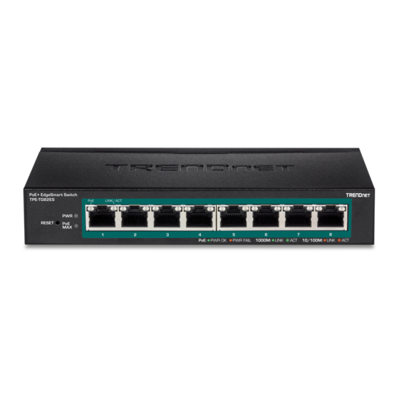
TPE‐TG82ES TRENDnet User’s Guide Product Hardware Features LED Indicators The desktop PoE managed switch includes LED indicators that convey port status Front View Gigabit PoE+ Ports Reset Button Diagnostic LEDs Rear View Power LED On When the Power LED is on, the device is receiving power. When the Power LED is off, the power adapter is not ... -
Page 6: Basic Installation
TPE‐TG82ES TRENDnet User’s Guide Basic Installation Gigabit Ethernet PoE+ Port LEDs (1‐8) Link/Activity button Mode Green When the Green LED is on, the respective port on: is connected to a 1Gbps Ethernet network. Amber When the Amber LED lights on, the respective on: port is connected to a 10/100Mbps Ethernet network. Green When the LED is blinking green, the port is ... - Page 7 TPE‐TG82ES TRENDnet User’s Guide 6. Click System and then click IPv4 Setup. 7. Configure the switch IP address settings to be within your network subnet, then click Apply. Note: You may need to modify the static IP address settings of your computer’s network adapter to IP address settings within your subnet in order to regain access to the switch. 5. In the left hand panel, click on Save 6. Click Save Settings to Flash, then click OK. Note: This step saves all configuration changes to the NV‐RAM to ensure that if the switch is rebooted or power cycled, the configuration changes will still be applied. © Copyright 2018 TRENDnet. All Rights Reserved. 4 ...
-
Page 8: Connect Additional Devices To Your Switch
TPE‐TG82ES TRENDnet User’s Guide Connect additional devices to your switch You can connect computers or other network devices to your switch using Ethernet cables to connect them to one of the available Gigabit Ethernet PoE+ Ports (1‐8). Check the status of the LED indicators on the front panel of your switch to ensure the physical cable connection from your computer or device. You can use the Gigabit Ethernet ports as network uplinks. Note: If you encounter issues connecting to your network, there may be a problem with your computer or device network settings. Please ensure that your computer or device network settings (also called TCP/IP settings) are configured properly within the network subnet your switch is connected. © Copyright 2018 TRENDnet. All Rights Reserved. 5 ... -
Page 9: Configure Your Switch
TPE‐TG82ES TRENDnet User’s Guide Switch Info Configure your switch View your switch status information Switch Info Access your switch management page You may want to check the general system information of your switch such as firmware Note: Your switch default management IP address http://192.168.10.200 is accessed version, boot loader information and system uptime. Other information includes through the use of your Internet web browser (e.g. Internet Explorer®, Firefox®, administration information, System MAC Address, IPv4 Information and Automatic Chrome™, Safari®, Opera™) and will be referenced frequently in this User’s Guide. Network Features information. 1. Open your web browser and go to the IP address http://192.168.10.200. Your switch 1. Log into your switch management page (see “Access your switch management page” will prompt you for a user name and password. on page 6). 2. Click on System Info. System Information 2. Enter the user name and password. By default: System Up For – The duration your switch has been running continuously without ... - Page 10 TPE‐TG82ES TRENDnet User’s Guide Administration Information Automatic Network Features System Name – Displays the identifying system name of your switch. This IPv4 DHCP Client Mode: Displays if your switch IPv4 address setting is set to information can be modified under the System section. DHCP client. System Location ‐ Displays the identifying system location of your switch. This information can be modified under the System section. System Contact – Displays the identifying system contact or system administrator of your switch. This information can be modified under the System section. System MAC Address, IPv4 Information MAC Address: Displays the switch system MAC address. IP Address – Displays the current IPv4 address assigned to your switch. Subnet Mask – Displays the current IPv4 subnet mask assigned to your switch. Default Gateway – Displays the current gateway address assigned to your switch. ...
-
Page 11: System
TPE‐TG82ES TRENDnet User’s Guide System 5. In the left hand panel, click on Save Set your system information System > System Management This section explains how to assign a name, location, and contact information for the switch. This information helps in identifying each specific switch among other switches in the same local area network. Entering this information is optional. 6. Click Save Settings to Flash, then click OK. Note: This step saves all configuration changes to the NV‐RAM to ensure that if the 1. Log into your switch management page (see “Access your switch management page” switch is rebooted or power cycled, the configuration changes will still be applied. on page 6). 2. Click on System, and click on System Management. 3. Review the settings. When you have completed making changes, click Apply to save the settings. ... -
Page 12: Set Your Ipv4 Settings
TPE‐TG82ES TRENDnet User’s Guide Set your IPv4 settings System > IPv4 Setup This section allows you to change your switch IPv4 address settings. Typically, the IP address settings should be changed to match your existing network subnet in order to access the switch management page on your network. Default Switch IPv4 Address: 192.168.10.200 Default Switch IPv4 Subnet Mask: 255.255.255.0 1. Log into your switch management page (see “Access your switch management page” on page 6). 2. Click on System, and click on IPv4 Setup. 4. Click Apply. 3. Review the settings. When you have completed making changes, click Apply to save the settings. System MAC Address: Displays the switch MAC address information. 5. In the left hand panel, click on Save System IP Address: Enter the new switch IP address. (e.g. 192.168.200.200) System Subnet Mask: Enter the new switch subnet mask. (e.g. 255.255.255.0) System Default Gateway: Enter the default gateway IP address. (e.g. ... -
Page 13: Change Administrator Password And Add Accounts
TPE‐TG82ES TRENDnet User’s Guide Change administrator password and add accounts System > Administration 5. Click Save Settings to Flash, then click OK. This section explains how to change the administrator password create additional Note: This step saves all configuration changes to the NV‐RAM to ensure that if the administrative user accounts for access to the switch management page. switch is rebooted or power cycled, the configuration changes will still be applied. 1. Log into your switch management page (see “Access your switch management page” on page 6). 2. Click on System, and click on Administration. 3. Review the settings. In the Password field, enter the new password and enter the new password again the Confirm Password field to verify. Then, click Apply. Note: The password consists of up to 12 alphanumeric characters. To create additional administrative user accounts: ... -
Page 14: Change Web Idle Login Timeout Settings
TPE‐TG82ES TRENDnet User’s Guide Change Web idle login timeout settings Enable or Disable SNMP System > Timeout System > SNMP > Global Settings This section explains how to modify the switch management page idle timeout settings. You can manage a switch by viewing and configuring the management information base (MIB) objects on the device with the Simple Network Management Program (SNMP). This chapter describes how to configure SNMP. A Group Name, IP address of the switch 1. Log into your switch management page (see “Access your switch management page” and at least one community string is the minimum required to manage the switch using on page 6). SNMP. 2. Click on System, and click on Timeout. Note: If you disable the SNMP on the switch, the switch will not be manageable via SNMP using MIBs. 3. Review the settings. Click Apply to save changes. 1. Log into your switch management page (see “Access your switch management page” on page 6). Web Idle Timeout ‐ Enter the idle period in minutes, when the switch will automatically log out a user from the switch management page. ... -
Page 15: Set The Snmp Community Settings
TPE‐TG82ES TRENDnet User’s Guide 2. Click on System, click on SNMP, and click on Community Table Settings.. 3. Review the settings. Click Apply to save the settings. Access Right: Assign users the level of access from the drop down menu Community Nsme: Input the name of this SNMP community. 4. In the left hand panel, click on Save 4. In the left hand panel, click on Save 5. Click Save Settings to Flash, then click OK. Note: This step saves all configuration changes to the NV‐RAM to ensure that if the 5. Click Save Settings to Flash, then click OK. switch is rebooted or power cycled, the configuration changes will still be applied. Note: This step saves all configuration changes to the NV‐RAM to ensure that if the switch is rebooted or power cycled, the configuration changes will still be applied. ... -
Page 16: Configure The Snmp Trap Management
TPE‐TG82ES TRENDnet User’s Guide Configure the SNMP Trap Management System > SNMP > Host Settings 5. In the left hand panel, click on Save A Host IP address is used to specify a management device that needs to receive SNMP traps sent by the switch. This IP address is associated with the SNMP Version and a valid Community Name in the Host table of the switch. 6. Click Save Settings to Flash, then click OK. 1. Log into your switch management page (see “Access your switch management page” Note: This step saves all configuration changes to the NV‐RAM to ensure that if the on page 6). switch is rebooted or power cycled, the configuration changes will still be applied. 2. Click on System, click on SNMP, and click on Host Settings. 3. Review the settings. Create Trap Host Table Entry Use the following procedure to create a trap Host table entry: ... -
Page 17: View Statistics
TPE‐TG82ES TRENDnet User’s Guide View Statistics System > Statistics Enable IEEE 802.3az Power Saving Mode Statistics provide important information for troubleshooting switch problems at the port System > IEEE 802.3az EEE level. The statistics traffic information support normal packets and Error packets The IEEE 802.3 EEE standard defines mechanisms and protocols intended to reduce the information. energy consumption of network links during periods of low utilization, by transitioning interfaces into a low‐power state without interrupting the network connection. The transmitted and received sides should be IEEE802.3az EEE compliance. By default, the View Traffic Information Statistics switch disabled the IEEE 802.3az EEE function. Users can enable this feature via the System > Statistics > Traffic IEEE802.3az EEE setting page. 1. Log into your switch management page (see “Access your switch management page” on page 6). 1. Log into your switch management page (see “Access your switch management page” on page 6). 2. Click on System, click on Statistics, and click on Traffic. 2. Click on Tools and click on IEEE 802.3az EEE. ... -
Page 18: Network
TPE‐TG82ES TRENDnet User’s Guide Disabled ‐ This parameter indicates the port is not able to send and Network receive Ethernet frames. Configure Physical Interfaces Mode: This parameter indicates the speed and duplex mode settings for the Network > Physical Interface port. You can use this parameter to set the speed and duplex mode of a port. This section allows you to configure the physical port parameters such as speed, duplex, The possible settings are: and flow control. This section also reports the current link status of each port and Auto ‐This parameter indicates the port is using Auto‐Negotiation to negotiated speed/duplex. set the operating speed and duplex mode. The actual operating speed and duplex mode of the port are displayed in parentheses (for 1. Log into your switch management page (see “Access your switch management page” example, “1000/F” for 1000 Mbps full duplex mode) after a port on page 6). establishes a link with an end node. 1000/Full ‐This parameter indicates the port is configured for 1000Mbps operation in full‐duplex mode. 2. Click on Network and click on Physical Interface. 100/Full ‐This parameter indicates the port is configured for 100Mbps operation in full‐duplex mode. ... -
Page 19: Configure Spanning Tree (Stp, Rstp)
TPE‐TG82ES TRENDnet User’s Guide Ignore ‐ This parameter indicates that the All setting does not apply to 2. Click on Network, click on Spanning Tree, and click on Protocol. the Flow Control field. In other words, each port is set individually. Enabled ‐ This parameter indicates that the port is permitted to use 3. Review the settings. Click Apply to save changes. flow control. Spanning Tree State: Select the STP state on the device. The possible field Disabled ‐ This parameter indicates that the port is not permitted to values are: use flow control. Disable – Disables STP on the device. This is the default value. Enable – Enables STP on the device. Spanning Tree Mode: Specifies the Spanning Tree Protocol (STP) mode to enable on the switch. The possible field values are: STP – Enables STP 802.1d on the device. RSTP – Enables Rapid STP 802.1w on the device. This is the default value. STP New Root Traps: Select the STP Root Trap on the device. The possible field values are: Disable – Disables STP Root Trap on the device. This is the default ... -
Page 20: Configure Spanning Tree Protocol Port Settings
TPE‐TG82ES TRENDnet User’s Guide Configure Spanning Tree Protocol port settings Network > Spanning Tree > RSTP Port Settings 1. Log into your switch management page (see “Access your switch management page” on page 6). 2. Click on Network, click on Spanning Tree, and click on RSTP Port Settings. 3. Review the settings. For each entry, click Apply to save changes. Port: Indicates the port number (1‐8) Port Fast: Select the spanning tree protocol for each port Network: Automatically lets the device determine the type of device that is connected to the port Disable: Disable port fast on a particular port. Edge: Indicates that this port is connected to an Edge device. In addition, this section also displays the spanning tree root information. 4. In the left hand panel, click on Save 5. Click Save Settings to Flash, then click OK. Note: This step saves all configuration changes to the NV‐RAM to ensure that if the ... -
Page 21: Configure Port Trunk Settings (Trunk/Link Aggregation)
TPE‐TG82ES TRENDnet User’s Guide Configure port trunk settings (Trunk/Link Aggregation) Network > Trunk The trunking function enables the cascading of two or more ports for a combined larger total bandwidth. Up to 4 trunk groups may be created, each supporting up to 8 ports. Add a trunking Name and select the ports to be trunked together, and click Apply to activate the selected trunking groups. Important Note: Do not connect the cables of a port trunk to the ports on the switch 5. In the left hand panel, click on Save until you have configured the ports on both the switch and the end nodes. Connecting the cables prior to configuring the ports can create loops in your network topology. Loops can result in broadcast storms which can severely limited the effective bandwidth of your network. 6. Click Save Settings to Flash, then click OK 1. Log into your switch management page (see “Access your switch management page” Note: This step saves all configuration changes to the NV‐RAM to ensure that if the on page 6). switch is rebooted or power cycled, the configuration changes will still be applied. 2. Click on Network, and click on Trunk. ... -
Page 22: Configure Port Mirror Settings
TPE‐TG82ES TRENDnet User’s Guide Configure port mirror settings Check the port to monitor or copy inormation from. (Source) Network > Mirroring To copy data received on a specific port, check the port number(s) under the Ingress Port section or you could click All to copy data received on all ports. Port mirroring allows you to monitor the ingress and egress traffic on a port by having the traffic copied to another port where a computer or device can be set up to capture To copy data transmitted on specific port, check the port number under the Egress Port the data for monitoring and troubleshooting purposes. section or you could click All to copy data transmitted on all ports. 1. Log into your switch management page (see “Access your switch management page” on page 6). 2. Click on Network, and click on Mirroring. 3. Review the settings. Click Apply to save changes. Mirroring Status – Click the drop‐down and list and select one of the following 4. In the left hand panel, click on Save options: Enable ‐ This parameter activates the Port Mirroring feature and the rest of the configuration parameters become active on the page. ... -
Page 23: Enable Loopback Detection
TPE‐TG82ES TRENDnet User’s Guide Enable loopback detection In the Loopback Detection table, select one of the Loopback Detection Status choices from the pull down menu: Network > Loopback Detection The loopback detection feature allows the switch to detect and prevent disruption from Enabled: This selection enables the Loopback Detection feature for each port. loops that occur on uplink or downlink switches directly connected to your switch. This state must be enabled along with the Status field at the top of the page before this feature can be active on the selected port. 1. Log into your switch management page (see “Access your switch management page” Disabled: This selection disables the Loopback Detection feature on the on page 6). selected port. Note: In the All row when you select Enable or Disable, the selection applies to all of the Switch ports. 2. Click on Network and click on Loopback Detection. Next to each entry modified, under the Action column, click Apply to save the changes. 3. Review the settings. ... -
Page 24: Add Static Unicast Entries To The Switch
TPE‐TG82ES TRENDnet User’s Guide Add static unicast entries to the switch multiple pages, you can navigate page number in the Page field and click Go or you can click First, Previous, Next, and Last Page to navigate the pages. Network > Static Unicast In this section, you can add static unicast entries to the switch configuration. 1. Log into your switch management page (see “Access your switch management page” on page 6). 2. Click on Network and click on Static Unicast. 3. Review the settings. 4. In the left hand panel, click on Save 802.1Q VLAN – Enter the VLAN ID where the MAC address will reside. Note: By default, all switch ports are part of the default VLAN, VLAN ID 1. MAC Address – Enter the MAC address of the device to add. 5. Click Save Settings to Flash, then click OK Port Member – Select the port where the MAC address will reside. ... -
Page 25: Add Static Multicast Entries To The Switch
TPE‐TG82ES TRENDnet User’s Guide Add static multicast entries to the switch In the list, you can click Modify to modify an entry or click Delete or delete the entry. If the entries span multiple pages, you can navigate page number in the Page field and Network > Static Multicast click Go or you can click First, Previous, Next, and Last Page to navigate the pages. In this section, you can add static multicast entries to the switch configuration. 1. Log into your switch management page (see “Access your switch management page” on page 6). 2. Click on Network and click on Static Multicast. 3. Review the settings. 4. In the left hand panel, click on Save 802.1Q VLAN – Enter the VLAN ID where the multicast group MAC address will reside. Note: By default, all switch ports are part of the default VLAN, VLAN ID 1. 5. Click Save Settings to Flash, then click OK MAC Address – Enter the multicast group MAC address. Note: This step saves all configuration changes to the NV‐RAM to ensure that if the ... -
Page 26: Configure Igmp Snooping Group Settings
TPE‐TG82ES TRENDnet User’s Guide Configure IGMP Snooping Settings Configure IGMP Snooping Group Settings Network > IGMP Snooping > Settings Network > IGMP Snooping > Group Settings 1. Log into your switch management page (see “Access your switch management page” 1. Log into your switch management page (see “Access your switch management page” on page 6). on page 6). 2. Click on Network, click on IGMP Snooping, and click on Settings. 2. Click on Network, click on IGMP Snooping, and click on Group Settings. 3. To enable IGMP Snooping, select Enable from the drop down menu under IGMP 3. Review the settings and click Add to save the settings. Snooping Status and click Apply. 802.1Q VLAN: Input the 802.1Q VLAN ID Group Address: Input the Group Address for the VLAN ID Group Member: Select the ports to be included in this group and click Add.. For all ports, click All and click Add to all ports the ports to this VLAN ID ... -
Page 27: Configure Storm Control
TPE‐TG82ES TRENDnet User’s Guide Configure Storm Control Set Ingress Rate Limiting Network > Bandwidth Control > Storm Control Network > Bandwidth Control > Ingress Rate Limiting This section allows you to configure the storm control threshold. This section allows you to set the ingress (receive) rate for each switch port. 1. Log into your switch management page (see “Access your switch management page” 1. Log into your switch management page (see “Access your switch management page” on page 6). on page 6). 2. Click on Network, click on Bandwidth Control, and click on Storm Control. 2. Click on Network, click on Bandwidth Control, and click on Ingress Rate Limiting. 3. Review the settings for each port. Click Apply to save the settings. 3. Review the settings for each port. Click Apply to save the settings. Storm Control Status – Click the drop‐down list and select Enabled to enable Bandwidth – Select the ingress rate limit value from the drop down menu. Storm Control. Note: Modifying settings in the row marked All, will apply the settings to all ports. ... -
Page 28: Set Egress Rate Limiting
TPE‐TG82ES TRENDnet User’s Guide Set Egress Rate Limiting Add, modify, and remove VLANs Network > Bandwidth Control > Egress Rate Limiting Network > VLAN > Tagged VLAN This section allows you to set the egress (transmit) rate for each switch port. A VLAN is a group of ports that can be anywhere in the network, but communicate as though they were in the same area. VLANs can be easily organized to reflect department groups (such as R&D, Marketing), 1. Log into your switch management page (see “Access your switch management page” usage groups (such as e‐mail), or multicast groups (multimedia applications such as on page 6). video conferencing), and therefore help to simplify network management by allowing users to move devices to a new VLAN without having to change any physical 2. Click on Network, click on Bandwidth Control, and click on Egress Rate Limiting. connections. 3. Review the settings for each port. Click Apply to save the settings. 1. Log into your switch management page (see “Access your switch management page” Bandwidth – Select the egress rate limit value from the drop down menu. on page 6). Note: Modifying settings in the row marked All, will apply the settings to all ports. ... - Page 29 TPE‐TG82ES TRENDnet User’s Guide Tagged/Untagged/Not Member VLAN Ports In the list, you can click Modify to modify an entry or click Delete or delete the entry. If the entries span multiple pages, you can navigate page number in the Page field and On a port, the tag information within a frame is examined when it is received to click Go or you can click First, Previous, Next, and Last Page to navigate the pages. determine if the frame is qualified as a member of a specific tagged VLAN. If it is, it is eligible to be switched to other member ports of the same VLAN. If it is determined that Note: The default VLAN VID1 cannot be removed. the frame’s tag does not conform to the tagged VLAN, the frame is discarded. Since these VLAN ports are VLAN aware and able to read VLAN VID tagged information on a frame and forward to the appropriate VLAN, typically tagged VLAN ports are used for uplink and downlink to other switches to carry and forward traffic for multiple VLANs across multiple switches. Tagged VLAN ports can be included as members for multiple VLANs. Computers and other edge devices are not typically connected to tagged VLAN ports unless the network interface on these device can be enabled to be VLAN aware. Select the tagged VLAN ports to add to the new VLAN. 4. In the left hand panel, click on Save Untagged VLAN ports are used to connect edge devices (VLAN unaware) such as 5. Click Save Settings to Flash, then click OK computers, laptops, and printers to a specified VLAN. It is required to modify the Port ...
-
Page 30: Configure Vlan Port Settings
TPE‐TG82ES TRENDnet User’s Guide Configure VLAN Port Settings overlapping untagged VLAN ports in order to create VLAN groups. It is recommended to use the standard 802.1Q VLAN mode when possible. Network > VLAN > Port IVL – Independent VLAN Learning In this section, you can modify the port VID settings, acceptable frame types, and ingress filtering. In order to modify these settings, you must first add VLANs before set SVL – Shared VLAN Learning (also known as asymmetric VLAN) up (see “Add, modify, and remove VLANs” on page 32). Please note the following when switching between forwarding table modes: FDB (Forwarding Database) will be cleared. 1. Log into your switch management page (see “Access your switch management page” Static Unicast Address entries will be cleared. on page 6). Static Multicast Address entries will be cleared. 802.1X authenticated records will be cleared. 2. Click on Network, click on VLAN, and click on Port. IGMP Snooping multicast group addresses will be cleared ... -
Page 31: View The Switch Vlan Dynamic Forwarding Table
TPE‐TG82ES TRENDnet User’s Guide Create a private VLAN Network > VLAN > Private The private VLAN feature allows you to create a more secure VLAN that is completely View the switch VLAN Dynamic forwarding table isolated to its members and cannot communicate with other VLANs Network > VLAN > Forwarding Table This section allows you to view the VLAN forwarding table with dynamically generated 1. Log into your switch management page (see “Access your switch management page” forwarding table entries as devices more devices are connected to your switch. on page 6). 1. Log into your switch management page (see “Access your switch management page” 2. Click on Network, click on VLAN, and click on Private. on page 6). 3. To configure Private VLAN Settings, perform the following procedure: 2. Click on Network, click on VLAN, and click on Forwarding Table. Select the Source Port to one of the following choices from the pull‐down menu: All, 01 – 08 3. By default, forwarding entries for all ports are listed. You can click the Port drop‐... - Page 32 TPE‐TG82ES TRENDnet User’s Guide © Copyright 2018 TRENDnet. All Rights Reserved. 29 ...
-
Page 33: Configuring Voice Vlans
TPE‐TG82ES TRENDnet User’s Guide Configuring Voice VLANs However, it is possible that you can find more than one OUI from the same manufacturer among the IP phones you are installing. It is also possible that your IP Network > Voice VLAN phones are from two or more different manufacturers in which case you will find This chapter contains a description of the Switch’s Voice VLAN feature and the different OUIs for each manufacturer. If you identify more than one OUI among the IP procedures to create, modify, and delete a voice VLAN configuration. phones being installed, then one MAC address representing each individual OUI must be The Voice VLAN feature is specifically designed to maintain high quality, uninterrupted configured in the voice VLAN. You can enter a total of 13 OUIs. voice traffic through the switch. When talking on a voice over IP phone, a user expects to have no interruptions in the conversation and excellent voice quality. The Voice VLAN Dynamic Auto‐Detection vs Static Ports feature can be configured to meet these requirements. Prior to configuring the voice VLAN, you must configure a tagged VLAN which is the basis for the voice VLAN configuration. The VLAN must be configured with one or more CoS with Voice VLAN tagged or untagged ports that will serve as the voice VLAN uplink/downlink. By default, The Voice VLAN CoS parameter maintains the voice quality between the ingress and a tagged or untagged port is a static member of a tagged VLAN. The ports that you egress ports of the switch. CoS must be enabled for the Voice VLAN CoS priority to take choose to configure as dynamic Auto‐Detection ports effect. The CoS priority level that you config is applied to voice traffic on all ports of the must be connected directly to an IP phone. When you initially define the ports of a ... -
Page 34: Create A Voice Vlan
TPE‐TG82ES TRENDnet User’s Guide Note: Link Layer Discovery Protocol for Media Endpoint Devices (LLDP‐ MED) is not Click Apply to save the settings. supported on the switch. Each IP phone that is VLAN aware should be manually configured for the VLAN ID that matches your voice VLAN ID. Each of the voice VLAN ports connected to an IP phone should be configured as “Not Member” ports of the tagged VLAN. Create a Voice VLAN Network > Voice VLAN > Settings Note: Prior to configuring your voice VLAN, you must first configure a tagged VLAN. This VLAN will be used as a basis for your voice VLAN. 1. Log into your switch management page (see “Access your switch management page” on page 6). 4. In the left hand panel, click on Save 2. Click on Network, click on Voice VLAN, and click on Settings. 3. Review the settings. 5. Click Save Settings to Flash, then click OK Use the following procedure to configure voice VLAN: Note: This step saves all configuration changes to the NV‐RAM to ensure that if the ... - Page 35 TPE‐TG82ES TRENDnet User’s Guide Use the following procedure to configure voice VLAN OUIs: 4. In the left hand panel, click on Save Default OUI: Select from the drop down menu for a list of pre‐defined Telephony OUIs. User defined OUI: Enter a text description that helps you identify the manufacturer’s OUI in the User Defined OUI ‐ Description field. This parameter 5. Click Save Settings to Flash, then click OK can be up to 20 characters in length. Enter the MAC address in the User Note: This step saves all configuration changes to the NV‐RAM to ensure that if the Defined OUI ‐ Telephony OUI field of one of the IP phones with the switch is rebooted or power cycled, the configuration changes will still be applied. manufacturer's OUI. Click Add. The new OUI entry is displayed in the table at the bottom of the page. Note: If you find more than one OUI among the IP phones you are installing, enter one MAC address that represents each individual OUI. You can enter a total of 10 OUIs. ...
-
Page 36: Qos (Quality Of Service)
TPE‐TG82ES TRENDnet User’s Guide QoS (Quality of Service) 5. Click Save Settings to Flash, then click OK When a port on an Ethernet switch becomes oversubscribed, its egress queues contain more packets than the port can handle in a timely manner. In this Note: This step saves all configuration changes to the NV‐RAM to ensure that if the situation, the port may be forced to delay the transmission of some packets, resulting in switch is rebooted or power cycled, the configuration changes will still be applied. the delay of packets reaching their destinations. A port may be forced to delay transmission of packets while it handles other traffic, and, in some situations, some packets destined to be forwarded to an oversubscribed port from other switch ports may be discarded. Minor delays are often of no consequence to a network or its performance. But there are applications, referred to as delay or time sensitive applications, which can be impacted by packet delays. Voice transmission and video conferences are two examples. Set Port Priority If packets carrying data in either of these cases are delayed from reaching their QoS > Port Priority destination, the audio or video quality may suffer. The Port Priority values are assigned to an untagged frame at ingress for internal This is where Cost of Service (CoS) is of value. It allows you to manage the flow of traffic processing in the switch. This procedure explains how to change the default mappings of through a switch by having the switch ports give higher priority to some packets, such as ... -
Page 37: Set The Scheduling Algorithm
TPE‐TG82ES TRENDnet User’s Guide 5. Click Save Settings to Flash, then click OK Note: This step saves all configuration changes to the NV‐RAM to ensure that if the switch is rebooted or power cycled, the configuration changes will still be applied. Set DSCP (Differentiated Services Code Point) Class Mapping settings QoS > DSCP If you choose to use the DSCP tags in your Access Control policy configuration, each DSCP value (0‐63) that is relevant to your configuration needs to be mapped to one of the four egress queues(Low, Medium, High, or Highest). The default queue for all DSCP 4. In the left hand panel, click on Save values is 0.To assign the queue mappings to the DSCP values, perform the following procedure. 1. Log into your switch management page (see “Access your switch management page” 5. Click Save Settings to Flash, then click OK on page 6). Note: This step saves all configuration changes to the NV‐RAM to ensure that if the switch is rebooted or power cycled, the configuration changes will still be applied. 2. Click on QoS and click on DSCP. ... - Page 38 TPE‐TG82ES TRENDnet User’s Guide Strict Priority ‐ The port transmits all packets out of higher priority queues before transmitting any from the lower priority queues. WRR (Weighted RoundRobin) ‐ The port transmits a set number of packets from each queue, in a round robin fashion, so that each has a chance to transmit traffic. 4. In the left hand panel, click on Save 5. Click Save Settings to Flash, then click OK Note: This step saves all configuration changes to the NV‐RAM to ensure that if the switch is rebooted or power cycled, the configuration changes will still be applied. © Copyright 2018 TRENDnet. All Rights Reserved. 35 ...
-
Page 39: Poe Configuration
TPE‐TG82ES TRENDnet User’s Guide Power Budget PoE Configuration Power budget is the maximum amount of power that the PoE switch can provide at one The main advantage of PoE is that it can make installing a network easier. The selection time to the connected PDs. Port Prioritization As long as the total power requirements of a location for a network device is often limited by whether there is a power source of the PDs is less than the total available power of the switch, it can supply power to all nearby. This constraint limits equipment placement or requires the added time and cost of the PDs. of having additional electrical sources installed. However, with PoE, you can install PoE However, when the PD power requirements exceed the total available power, the compatible devices wherever they are needed without having to worry about whether switch denies power to some ports based on a process called port prioritization. there is power source nearby. The ports on the PoE switch are assigned to one of three priority levels. These levels and descriptions are listed in Table 3. Without enough power to support all the ports set to Power Sourcing Equipment (PSE) the same priority level at one time, the switch provides power to the ports based on the A device that provides PoE to other network devices is referred to as power sourcing port number, in ascending order. For example, when all of the ports in the switch are set equipment (PSE). The Gigabit Web Smart PoE+ Switch is a PSE device which provides DC to the low priority level and the power requirements are exceeded on the switch, port 1 power to the network cable and functions as a central power source for other network has the highest priority level, port 2 has the next highest priority level and so forth. devices. ... -
Page 40: Configure Poe Settings
TPE‐TG82ES TRENDnet User’s Guide Configure PoE settings 4. In the left hand panel, click on Save PoE > Power over Ethernet 1. Log into your switch management page (see “Access your switch management page” on page 6). 5. Click Save Settings to Flash, then click OK Note: This step saves all configuration changes to the NV‐RAM to ensure that if the switch is rebooted or power cycled, the configuration changes will still be applied. 2. Click on PoE and click on Power over Ethernet. Configure PoE settings 3. Review the settings for each port. Next to each port entry, click Apply to save the settings. PoE > PoE Configuration Power Over Ethernet Power Threshold – Input the maximum PoE budget (in 1. Log into your switch management page (see “Access your switch management page” watts) that can be used. (between 7.1 – 64 watts) on page 6). ... - Page 41 TPE‐TG82ES TRENDnet User’s Guide UserDef – After UserDef is selected in the PowerLimit cell, users can define the maximum power consumption for a specific port. Note: The User Defined power limit ranges between 1.0 and 30.0 watts. Legacy Support – When Legacy Support is enabled, the port sends out Passive PoE requirements to the device connected to the port. Note: Doing so, may damage the device connected to the devices’ ports. Power(W) ‐ Indicates the Power in watts that the port is supplying power to the PD. Voltage (V) ‐ Indicates the Voltage in volts as measured at the port when the port is supplying power to the PD. Current (mA) ‐ Indicates the Current in milliamps that the port is supplying to the PD. 4. In the left hand panel, click on Save 5. Click Save Settings to Flash, then click OK Note: This step saves all configuration changes to the NV‐RAM to ensure that if the switch is rebooted or power cycled, the configuration changes will still be applied. ...
-
Page 42: Switch Maintenance
TPE‐TG82ES TRENDnet User’s Guide Firmware Upgrade via HTTP Settings Switch Maintenance Tools > Firmware Upgrade Upgrade your switch firmware 1. Log into your switch management page (see “Access your switch management page” Tools > Firmware Upgrade on page 6). TRENDnet may periodically release firmware upgrades that may add features or fix problems associated with your TRENDnet switch model and version. To check if there is 2. Click on Tools, click on Firmware Upgrade. a firmware upgrade available for your device, please check your TRENDnet model and version using the link. http://www.trendnet.com/downloads/ 3. Depending on your web browser, in the via HTTP Settings section, click Upgrade and In addition, it is also important to verify if the latest firmware version is newer than the click Ok on the prompt. one your switch is currently running. To identify the firmware that is currently loaded on your switch, log in to the switch, click on the System Info section or click on Tools and click on Firmware Upgrade. The firmware used by the switch is listed as Runtime Image or Image Version. If there is a newer version available, also review the release notes to check if there were any new features you may want or if any problems were fixed that you may have been experiencing. 4. Wait for the 15 seconds and click continue. ... -
Page 43: Backup And Restore Your Switch Configuration Settings
TPE‐TG82ES TRENDnet User’s Guide Backup and restore your switch configuration settings Cable Diagnostics Test Tools > Configuration > Backup/Restore Tools > Diagnostics You may have added many customized settings to your switch and in the case that you The switch provides a basic cable diagnostic tool in the GUI for verifying the pairs in need to reset your switch to default, all your customized settings would be lost and copper cabling and estimated distance for troubleshooting purposes. would require you to manually reconfigure all of your switch settings instead of simply restoring from a backed up switch configuration file. The configuration will be backed up Note: or restored only to the currently used image. 1. If the cable length displays N/A, it means that the cable length is Not Available. The may be due to the port being unable to determine the estimated cable length. If length is Backup/Restore via HTTP Settings displayed as “N/A” it means the cable length is “Not Available”. This is due to the port To backup your switch configuration: being unable to obtain cable length/either because its link speed is 10M or 100M, or the cables used are broken and/or of bad in quality. 1. Log into your switch management page (see “Access your switch management page” on page 6). 2. Click on Tools, and click on Configuration. 2. The deviation of “Cable Fault Distance” is +/‐ 2 meters. No cable may be displayed in the table when the cable is less than 2 meters in length. ... -
Page 44: Reboot/Reset To Factory Defaults
TPE‐TG82ES TRENDnet User’s Guide The results will be displayed in the Cable Diagnostic Table below. Reboot/Reset to factory defaults Tools > Reboot This section provides the procedures for rebooting or resetting the switch to factory default settings. To reboot your switch: You may want to reboot your switch if you are encountering difficulties with your switch Test Results: Displays the diagnostic results for each pair in the cable. One of and have attempted all other troubleshooting. the following cable status parameters is displayed: Note: You may want to save the settings to flash before reboot the switch under Save OK: There is no problem detected with the cable. Settings to Flash (menu) > Save Settings to Flash (button). If you have not saved your Open in Cable: There is an open wire within the cable. current configuration settings to flash first, the configuration changes will be lost after a Short in Cable: Two wires are shorted together within the cable. reboot. Cross talk in Cable: There is crosstalk detected between one pair of wires and another pair within the cable. There are two methods that can be used to reboot your switch. Cable Fault Distance: This parameter specifies the distance from the switch ... -
Page 45: Using The Edgesmart Switch Management Utility
TPE‐TG82ES TRENDnet User’s Guide To reset your switch to factory defaults: Using the EdgeSmart Switch Management Utility You may want to reset your switch to factory defaults if you are encountering difficulties with your switch and have attempted all other troubleshooting. Before you reset your The Web Smart Management Utility allows you to do the following: switch to defaults, if possible, you should backup your switch configuration first, see “Backup and restore your switch configuration settings” on page 82. You can easily discover all TRENDnet edgesmart switches on your network using the discover feature. You can modify the IP address settings, change the admin password, and There are two methods that can be used to reset your switch to factory defaults. upgrade firmware for multiple switches. Hardware Method: Using a paper clip, on the front panel of the switch, push and hold the Reset button more than 6 seconds and release. Located on the front panel of your switch, see “Product Hardware Features” on page 2. Use System Requirements this method if you are encountering difficulties with accessing your switch management page. Operating System: Windows® 10 (32/64‐bit), 8 (32/64‐bit), Windows 7 (32/64‐bit), Vista ... - Page 46 TPE‐TG82ES TRENDnet User’s Guide 4. At the Install Location installation window, click Next. 6. In the Completion window, click Finish. 5. At the Installation, click Install. © Copyright 2018 TRENDnet. All Rights Reserved. 43 ...
-
Page 47: Using The Utility
TPE‐TG82ES TRENDnet User’s Guide Using the Utility Launching the Utility Upon completing the software installation, a desktop shortcut is automatically created. Double‐click the icon to start the utility or open the utility if it is already running. Closing the utility will exit the application. You can also click Exit at the bottom of the utility user interface to exit the application. You can also launch the utility from the Start Menu programs. Start > Programs (or All Programs) > TRENDnet Management Utility > TRENDnet Management Utility.exe © Copyright 2018 TRENDnet. All Rights Reserved. 44 ... -
Page 48: Discovery List
TPE‐TG82ES TRENDnet User’s Guide Discovery List Monitor List This is the list where you can discover all the Web management devices in your network. All the Web Smart switches in the Monitor List can be monitored; you can also receive the trap and show the status of the device. By pressing the “Discovery” button, you can list all the Web Smart Management System word definitions in the Monitor List: switches in the discovery list. S: Shows the system symbol of the Web‐Smart device, represent for device Double click or press the “Add to monitor list” button to select a device from the system is not alive. Discovery List to the Monitor List. IP Address: Shows the current IP address of the device. ... -
Page 49: Device Setting
TPE‐TG82ES TRENDnet User’s Guide Device Setting Firmware Upgrade: When the device has a new function, there will be a new firmware to update the device, use this function to update. You can set the device by using the function key in the Device Setting Dialog box. Configuration Setting: In this Configuration Setting, you can set the IP Address, Subnet Mask, Gateway, Group Interval, System name, Location and IP Mode. Select the device in the Discovery list or Monitor List and press this button, then the Configuration Setting window will appear, after entering the data that you want to ... -
Page 50: Main Menu Options
TPE‐TG82ES TRENDnet User’s Guide Main Menu Options In the “File TAB”, there are Monitor Save, Monitor Save As, Monitor Load and Exit. Monitor Save: To record the setting of the Monitor List to the default, when you open the Web Management Utility next time, it will auto load the default recorded setting. Monitor Save As: To record the setting of the Monitor List in appointed filename and file path. Monitor Load: To manually load the setting file of the Monitor List. Exit: To exit the Web Management Utility. ... -
Page 51: Technical Specifications
Limited Warranty TRENDnet User’s Guide SNMP v1, v2c Technical Specifications Cable diagnostic test Standards Backup/Restore Configuration IEEE 802.1d Upload Firmware IEEE 802.1w IEEE 802.1p Spanning Tree ... - Page 52 Limited Warranty TRENDnet User’s Guide 171 x 97.8 x 28.6mm (6.73 x 3.85 x 1.12 in.) Storm Control Broadcast (Min. Limit: 8Kbps) Weight Multicast (Min. Limit: 8Kbps) 423g (14.92 oz.) ...
-
Page 53: Troubleshooting
Limited Warranty TRENDnet User’s Guide Troubleshooting Q: If my switch IP address is different than my network’s subnet, what should I do? Answer: Q: I typed http://192.168.10.200 in my Internet Browser Address Bar, but an error You should still configure the switch first. After all the settings are applied, go to the message says “The page cannot be displayed.” How can I access the switch switch configuration page, click on System, click IPv4 Setup and change the IP address of management page? the switch to be within your network’s IP subnet. Click Apply, then click OK. Then click Answer: Save Settings to Flash (menu) and click Save Settings to Flash to save the IP settings to 1. Check your hardware settings again. See “Switch Installation” on page 4. the NV‐RAM. 2. Make sure the Power and port Link/Activity and WLAN lights are lit. 3. Make sure your network adapter TCP/IP settings are set to Use the following IP Q: I changed the IP address of the switch, but I forgot it. How do I reset my switch? address or Static IP(see the steps below). Answer: 4. Make sure your computer is connected to one of the Ethernet switch ports. Using a paper clip, push and hold the reset button on the front of the switch and release 5. Since the switch default IP address is 192.168.10.200, make sure there are no other after 6~10 seconds. network devices assigned an IP address of 192.168.10.200 The default IP address of the switch is 192.168.10.200. The default user name and ... -
Page 54: Appendix
Limited Warranty TRENDnet User’s Guide Note: If you are experiencing difficulties, please contact your computer or operating Appendix system manufacturer for assistance. How to find your IP address? Note: Please note that although the following procedures provided to follow for your How to configure your network settings to use a static IP address? operating system on configuring your network settings can be used as general Note: Please note that although the following procedures provided to follow for your guidelines, however, it is strongly recommended that you consult your computer or operating system on configuring your network settings can be used as general operating system manufacturer directly for assistance on the proper procedure for guidelines, however, it is strongly recommended that you consult your computer or configuring network settings. operating system manufacturer directly for assistance on the proper procedure for configuring network settings. Command Prompt Method Windows 2000/XP/Vista/7/8.1/10 Windows 7/8.1/10 1. On your keyboard, press Windows Logo+R keys simultaneously to bring up the Run a. Go into the Control Panel, click Network and Sharing Center. dialog box. b. Click Change Adapter Settings, right‐click the Local Area Connection icon. 2. In the dialog box, type cmd to bring up the command prompt. c. Then click Properties and click Internet Protocol Version 4 (TCP/IPv4). ... - Page 55 Limited Warranty TRENDnet User’s Guide In MAC OS 10.4, from the Show drop‐down list, select Built‐in Ethernet and select the TCP/IP tab. In MAC OS 10.5/10.6, in the left column, select Ethernet. e. Configure TCP/IP to use a static IP. In MAC 10.4, from the Configure IPv4, drop‐down list, select Manually and assign your network adapter a static IP address. Then click the Apply Now button. In MAC 10.5/10.6, from the Configure drop‐down list, select Manually and assign your network adapter a static IP address . Then click the Apply button. f. Restart your computer. Note: If you are experiencing difficulties, please contact your computer or operating system manufacturer for assistance. How to find your MAC address? In Windows 2000/XP/Vista/7/8.1/10, Your computer MAC addresses are also displayed in this window, however, you can type getmac –v to display the MAC addresses only. In MAC OS 10.4, 1. Apple Menu > System Preferences > Network 2. From the Show menu, select Built‐in Ethernet. 3. On the Ethernet tab, the Ethernet ID is your MAC Address. ...
- Page 56 Limited Warranty TRENDnet User’s Guide Federal Communication Commission Interference Statement RoHS This device complies with Part 15 of FCC Rules. Operation is subject to the following two This product is RoHS compliant. conditions: (1) this device may not cause harmful interference, and (2) this device must accept any interference received; including interference that may cause undesired operation. This equipment has been tested and found to comply with the limits for a Class B digital device, pursuant to part 15 of the FCC Rules. These limits are designed to provide reasonable protection against harmful interference in a residential installation. This equipment Europe – EU Declaration of Conformity generates, uses and can radiate radio frequency energy and, if not installed and used in accordance with the instructions, may cause harmful interference to radio communications. However, there is no guarantee that interference will not occur in a particular installation. If EN 60950‐1:2006+A11:2009+A1:2010+A12:2011+A2:2013 this equipment does cause harmful interference to radio or television reception, which can EN 55032:2015 (CISPR32:2012) (Class B) ...
- Page 57 Limited Warranty TRENDnet User’s Guide In the event that, after evaluation, TRENDnet cannot replace the defective product or Limited Warranty there is no comparable model available, we will refund the depreciated value of the TRENDnet warrants only to the original purchaser of this product from a TRENDnet product. authorized reseller or distributor that this product will be free from defects in material and workmanship under normal use and service. This limited warranty is non‐ If a product does not operate as warranted during the applicable warranty period, transferable and does not apply to any purchaser who bought the product from a TRENDnet shall reserve the right, at its expense, to repair or replace the defective reseller or distributor not authorized by TRENDnet, including but not limited to product or part and deliver an equivalent product or part to the customer. The purchases from Internet auction sites. repair/replacement unit's warranty continues from the original date of purchase. All products that are replaced become the property of TRENDnet. Replacement products Limited Warranty may be new or reconditioned. TRENDnet does not issue refunds or credit. Please contact the point‐of‐purchase for their return policies. TRENDnet warrants its products against defects in material and workmanship, under normal use and service. Specific warranty periods are listed on each of the respective product pages on the TRENDnet website. TRENDnet shall not be responsible for any software, firmware, information, or memory data of customer contained in, stored on, or integrated with any products returned to ...
- Page 58 Limited Warranty TRENDnet User’s Guide shipping from outside of the USA and Canada are responsible for any return shipping CONTRACT OR TORT (INCLUDING NEGLIGENCE), FOR INCIDENTAL, CONSEQUENTIAL, and/or customs charges, including but not limited to, duty, tax, and other fees. INDIRECT, SPECIAL, OR PUNITIVE DAMAGES OF ANY KIND, OR FOR LOSS OF REVENUE OR PROFITS, LOSS OF BUSINESS, LOSS OF INFORMATION OR DATE, OR OTHER FINANCIAL LOSS ARISING OUT OF OR IN CONNECTION WITH THE SALE, INSTALLATION, Refurbished product: Refurbished products carry a 90‐day warranty after date of MAINTENANCE, USE, PERFORMANCE, FAILURE, OR INTERRUPTION OF THE POSSIBILITY purchase. Please retain the dated sales receipt with purchase price clearly visible as OF SUCH DAMAGES, AND LIMITS ITS LIABILITY TO REPAIR, REPLACEMENT, OR REFUND evidence of the original purchaser's date of purchase. Replacement products may be OF THE PURCHASE PRICE PAID, AT TRENDNET'S OPTION. THIS DISCLAIMER OF LIABILITY refurbished or contain refurbished materials. If TRENDnet, by its sole determination, is FOR DAMAGES WILL NOT BE AFFECTED IF ANY REMEDY PROVIDED HEREIN SHALL FAIL unable to replace the defective product, we will offer a refund for the depreciated value OF ITS ESSENTIAL PURPOSE. of the product. Governing Law: This Limited Warranty shall be governed by the laws of the state of WARRANTIES EXCLUSIVE: IF THE TRENDNET PRODUCT DOES NOT OPERATE AS California. WARRANTED ABOVE, THE CUSTOMER'S SOLE REMEDY SHALL BE, AT TRENDNET'S OPTION, REPAIR OR REPLACE. THE FOREGOING WARRANTIES AND REMEDIES ARE EXCLUSIVE AND ARE IN LIEU OF ALL OTHER WARRANTIES, EXPRESSED OR IMPLIED, ...
- Page 59 ...
Need help?
Do you have a question about the TPE-TG82ES and is the answer not in the manual?
Questions and answers