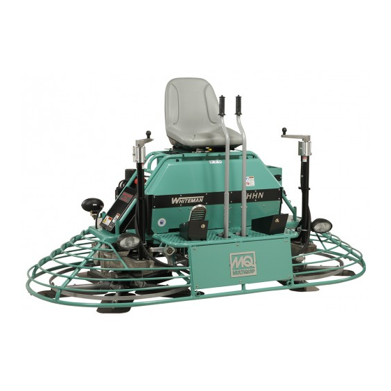
MULTIQUIP Whiteman Series Operation Manual
Ride-on trowel
(vanguard 540000 gasoline engine)
Hide thumbs
Also See for Whiteman Series:
- Manual (100 pages) ,
- Operation and parts manual (82 pages) ,
- Operation manual (80 pages)
Table of Contents
Advertisement
Advertisement
Table of Contents
Troubleshooting

Related Manuals for MULTIQUIP Whiteman Series


Summary of Contents for MULTIQUIP Whiteman Series
- Page 1 OPERATION MANUAL SERIES MODEL HHNG5 RIDE-ON TROWEL (VANGUARD 540000 GASOLINE ENGINE) Revision #1 (07/05/18) To find the latest revision of this publication, visit our website at: www.multiquip.com THIS MANUAL MUST ACCOMPANY THE EQUIPMENT AT ALL TIMES. PN: 30039...
-
Page 2: Proposition 65 Warning
PROPOSITION 65 WARNING Engine exhaust some its constituents, and some dust created by power sanding, sawing, grinding, drillingandotherconstructionactivities contains chemicals known to the State of California to cause cancer, birth defects and other reproductive harm. Some examples of these chemicals are: Leadfromlead-basedpaints. -
Page 3: Silicosis/Respiratory Warnings
SILICOSIS/RESPIRATORY WARNINGS WARNING WARNING SILICOSIS WARNING RESPIRATORY HAZARDS Grinding/cutting/drilling of masonry, concrete, metal and Grinding/cutting/drilling of masonry, concrete, metal and other materials with silica in their composition may give other materials can generate dust, mists and fumes off dust or mists containing crystalline silica. Silica is a containing chemicals known to cause serious or fatal basic component of sand, quartz, brick clay, granite and injury or illness, such as respiratory disease, cancer,... -
Page 4: Table Of Contents
TABLE OF CONTENTS HHNG5 Ride-On Trowel Proposition 65 Warning ........... 2 Silicosis/Respiratory Warnings ........ 3 Table Of Contents ............ 4 Training Checklist ............ 6 Daily Pre-Operation Checklist ......... 7 Safety Information ..........8–14 Lifting And Transporting ........15–17 Specifications ............18 Dimensions ............ - Page 5 NOTES HHNG5 RIDE-ON TROWEL • OPERATION MANUAL — REV. #1 (07/05/18) — PAGE 5...
-
Page 6: Training Checklist
TRAINING CHECKLIST Training Checklist Description Date Read operation manual completely. Machine layout, location of components, checking of engine oil level. Fuel system, refueling procedure. Operation of spray and lights. Operation of controls (machine not running). Safety controls, safety stop switch operation. -
Page 7: Daily Pre-Operation Checklist
DAILY PRE-OPERATION CHECKLIST Daily Pre-Operation Checklist Engine oil level Radiator coolant level Condition of blades Blade pitch operation Safety stop switch operation Steering control operation HHNG5 RIDE-ON TROWEL • OPERATION MANUAL — REV. #1 (07/05/18) — PAGE 7... -
Page 8: Safety Information
SAFETY INFORMATION Do not operate or service the equipment before reading Potential hazards associated with the operation of this the entire manual. Safety precautions should be followed equipment will be referenced with hazard symbols which at all times when operating this equipment. may appear throughout this manual in conjunction with Failure to read and understand the safety safety messages. - Page 9 SAFETY INFORMATION DECALS Decals associated with the operation of this equipment WARNING are defi ned below. Entanglement/Crush Hazard DO NOT operate equipment with guards removed. Serious bodily injury could result. Keep hands and fingers clear of gears. DANGER WARNING Flying Objects Hazard Lifting/Crush Hazard DO NOT disassemble spring cylinders without NEVER allow any person to stand...
- Page 10 SAFETY INFORMATION GENERAL SAFETY „ NEVER use accessories or attachments that are not recommended by Multiquip for this equipment. Damage CAUTION to the equipment and/or injury to user may result. „ NEVER operate this equipment without proper protective „ ALWAYS know the location of the nearest clothing, shatterproof glasses, respiratory protection, fi re extinguisher.
- Page 11 SAFETY INFORMATION ENGINE SAFETY WARNING „ If applicable, NEVER use your hand to fi nd WARNING hydraulic leaks. Use a piece of wood or „ DO NOT place hands or fingers inside engine cardboard. Hydraulic fl uid injected into the compartment when engine is running.
- Page 12 SAFETY INFORMATION FUEL SAFETY WARNING „ ALWAYS wear safety glasses when DANGER handling the battery to avoid eye irritation. „ DO NOT start the engine near spilled fuel or combustible The battery contains acids that can cause fl uids. Fuel is extremely fl ammable and its vapors can injury to the eyes and skin.
- Page 13 SAFETY INFORMATION TOWING SAFETY NOTICE „ The easiest way to lift the trowel is to utilize the lift loops CAUTION that are welded to the frame. These lift loops are located „ Check with your local county or state safety to the left and right sides of the operator’s seat.
-
Page 14: Safety Information
SAFETY INFORMATION EMISSIONS INFORMATION „ Trailer should be adjusted to a level position at all times when towing. NOTICE „ Raise and lock trailer wheel stand in up position when The gasoline engine used in this equipment has been towing. designed to reduce harmful levels of carbon monoxide „... -
Page 15: Lifting And Transporting
Failure to comply with these lifting the parts manual included with your trowel for part numbers, instructions may result in sling failure and order from your Multiquip parts dealer or importer. and severe personal injury or death. Only qualified personnel with proper training should perform this procedure. - Page 16 LIFTING AND TRANSPORTING The Occupational Safety and Health Administration (OSHA) Regulation 29 CFR Part 1926.251 (e)(8)—Removal from service requires that the slings be inspected prior to each use, and removed from service immediately if any of the following conditions are found: „...
-
Page 17: Lifting And Transporting
LIFTING AND TRANSPORTING LIFTING PROCEDURE 2. Insert forklift forks through the loops at the ends of the lifting slings (Figure 2). Keep the slings as close The correct lifting slings (Figure 1) have been supplied with to vertical as possible. If the choke angle (Figure 3) is your trowel, in accordance to its weight per Occupational 120 degrees or less, the lifting strength of the slings Safety and Health Administration (OSHA) Regulation... -
Page 18: Specifications
SPECIFICATIONS Table 2. HHNG5 Specifications Operating weight 1,083 lb. (495 kg) Shipping weight 1,368 lb. (620 kg) Fuel tank capacity 5 gallons (19 liters) Rotor speed 0–180 rpm Path width 92 in. (233 cm) Gearbox oil capacity 144 oz. (4.26 liters) Gearbox oil type ISO 22O AGMA GR 5EP Table 3. -
Page 19: Dimensions
DIMENSIONS Figure 4. HHNG5 Dimensions Table 5. HHNG5 Dimensions Measurement in. (cm) (A) Length 97 (246) (B) Height (seat) 50 (127) (C) Height (crank handle) 46 (117) (D) Width 46 (117) HHNG5 RIDE-ON TROWEL • OPERATION MANUAL — REV. #1 (07/05/18) — PAGE 19... -
Page 20: General Information
Please contact your nearest of finishing from low speed/high torque to high speed Multiquip dealer should a replacement manual be required. burnishing. Blades The blades of the trowel finish the concrete as they are swirled around the surface. -
Page 21: General Information
GENERAL INFORMATION HOW IT WORKS The Multi-Clutch functions much like a standard CVT system. As the engine RPMs increase, the drive or primary clutch closes, forcing the belt to ride outwards on the drive sheaves. The closing of the drive clutch also forces the belt to open the driven or secondary sheaves. -
Page 22: Components
COMPONENTS 1/10 HOURS MC-6LC www.LOFA.net Figure 5. HHNG5 Components (Front) 1. Steering Control Lever (Right Side) — Allows the 10. Twin Pitch Control (Left) — Adjusts blade pitch for unit to move in either a forward, reverse, left or right the left side of the trowel. -
Page 23: Components
COMPONENTS Figure 6. HHNG5 Components (Rear) 20. Left Rear Light — 55-watt, 12 VDC, Hella™ halogen 30. Right and Left Side Retardant Spray Pumps — light is provided for night time and indoor work. Delivers retardant to the spray nozzles. 21. -
Page 24: Basic Engine
BASIC ENGINE Table 6. Figure 7. Basic Engine Components INITIAL SERVICING 8. Oil Filter — Spin-on type, filters oil for contaminants. The gasoline engine (Figure 7) must be checked for proper lubrication and filled with fuel prior to operation. Refer to the 9. -
Page 25: Setup
SETUP SEAT ASSEMBLY The purpose of this section is to assist the user in setting up a NEW trowel. If your trowel is already assembled (seat, The seat is not installed on the trowel for shipping purposes. handles, knobs, and battery), this section can be skipped. To attach the seat perform the following: NOTICE 1. -
Page 26: Setup
SETUP BATTERY SETUP This trowel was shipped with a wet charged battery. This battery may need to be charged for a brief period of time as per the manufacturer instructions. CAUTION Use all safety precautions specified by the battery manufacturer when working with the battery. To install the battery onto the trowel, make sure that the battery is well seated in the battery box. -
Page 27: Inspection
INSPECTION GEARBOX OIL LEVEL This section is intended to assist the operator with the initial inspection of the trowel. It is extremely important that 1. Check the gearbox oil level in both gearboxes by this section be read carefully before attempting to use the viewing the sight glass at the rear of the gearbox. -
Page 28: Operation
OPERATION STARTING THE ENGINE 3. If starting a cold engine, pull the choke knob (Figure 14) upward to the CLOSED position. 1. Place one foot on the trowel’s platform, grab any part CHOKE of the frame, lift yourself onto the trowel, and sit down KNOB in the operator’s seat. - Page 29 OPERATION STEERING 6. Keeping your foot OFF the right foot pedal, turn the ignition key fully clockwise and listen for the engine to Two control levers located in front of the operator’s seat start. Once the engine has started, release the ignition provide directional control for the trowel.
-
Page 30: Operation
OPERATION 6. Push both the left and right joysticks backward and Matching Blade Pitch for Both Sets of Blades repeat steps 3 through 6 while substituting the word Trowels equipped with Twin Pitch™ controls may need reverse for forward. to have blade pitch syncronized between the two sets of Table 8. -
Page 31: Maintenance
MAINTENANCE Table 9. Engine Maintenance Schedule EVERY 6 EVERY BEFORE FIRST EVERY 2 DESCRIPTION MONTHS YEAR OPERATION EACH MONTH OR YEARS OR OR 100 OR 300 20 HRS. 500 HRS. HRS. HRS. Check Engine Oil Change Engine Oil Filter Replace Every 200 Hrs. - Page 32 MAINTENANCE Air Cleaner When performing any maintenance on the trowel or engine, follow all safety messages and rules for safe operation Thoroughly remove dirt and oil from the engine and stated at the beginning of this manual. control area. Clean or replace the air cleaner elements as necessary.
- Page 33 MAINTENANCE Air Cleaner Cleaning Changing Engine Oil (100 Hours) NOTICE CAUTION Always drain the engine oil while the oil is warm. Wear protective equipment such as approved safety glasses or face shields 1. Remove the oil drain bolt and sealing washer and allow and dust masks or respirators when the oil to drain into a suitable container (Figure 22).
- Page 34 MAINTENANCE Fuel Filter (200 Hours) 8. When installing a new spark plug, tighten 1/2 turn after the spark plug seats to compress the washer. Replace the fuel filter (Figure 24) every 200 hours. 9. When reinstalling the original spark plug, tighten 1/8–1/4 turn after the spark plug seats to compress FUEL the washer.
- Page 35 MAINTENANCE TROWEL LUBRICATION 2. Wipe the Zerk grease fitting clean to prevent abrasive material from entering the fitting during lubrication. Regular lubrication is required to maintain your trowel 3. Lubricate the Zerk grease fitting with 1–1½ shots of in optimal working condition. Schedule maintenance multipurpose grade grease.
- Page 36 MAINTENANCE Pillow Block Bearings (Daily) Pitch Adjustment Levers (Monthly) Perform the following lubrication procedure after every Perform the following lubrication procedure once a month. 8 hours of use. 1. Locate the Zerk grease fitting next to the knob on either 1.
- Page 37 MAINTENANCE Pitch Tower (Every 6 Months) CHECKING THE DRIVE BELT Perform the following lubrication procedure once every The drive belt needs to be changed as soon as it begins 6 months. to show signs of wear. NEVER reuse a belt under any circumstances.
- Page 38 MAINTENANCE BELT MEASUREMENT 2. Disconnect the left-side CV axle from the left-side gearbox and the lower drive pulley coupler. See Long life can be expected for this drive assembly as long Figure 34. as the drive belt is kept properly aligned. NOTICE The clutch will not shift correctly if the drive belt width is Note that the 3 bolts securing the CV axle to the coupler...
- Page 39 MAINTENANCE INSTALLING THE DRIVE BELT 3. Apply a thin coat of RVT silicone to the mating surfaces of the CV-joint (Figure 37) and left-side gearbox 1. Place the new CVT belt over the lower pulley coupler. (Figure 35). Squeeze and pull the belt upwards and APPLY SILICONE towards the rear of the trowel.
- Page 40 MAINTENANCE The easiest and most consistent way to make adjustments 2. Remove the bolts and lock washers on the trowel arm, on the trowel arm fingers is to use the Trowel Arm Adjustment then remove the blade. Fixture (P/N 9177). It comes with all the hardware necessary 3.
- Page 41 MAINTENANCE Spider Removal 1. To determine which blades need adjustment, place the trowel in the test area (3/4 inch thick plate)and look for Remove the spider assembly from the gearbox shaft as the following conditions: follows: 2. Pitch the blades as flat as possible. The adjustment 1.
- Page 42 MAINTENANCE Trowel Blade Removal 2. Each trowel arm is held in place at the spider plate (Figure 44) by a hex head bolt (zerk grease fitting) and Remove the trowel blades by removing the three hex head a roll pin. Remove both the hex head bolt and the roll bolts (Figure 42) from the trowel arm.
- Page 43 MAINTENANCE Checking Trowel Arm Straightness Trowel Arm Adjustment Fixture Trowel arms can be damaged by rough handling (such as Shown in (Figure 48) is the adjustment fixture with a trowel dropping the trowel on the pad), or by striking exposed arm inserted.
- Page 44 MAINTENANCE 3. Unscrew the locking bolts on the adjustment tool and 4. Repeat steps 2–3 for each trowel arm. place the trowel arm into the fixture channel as shown 5. Make sure that the spring tensioner is in the correct in Figure 50.
-
Page 45: Maintenance
MAINTENANCE INSTALLING PANS ONTO FINISHER BLADES DECOMMISSIONING TROWEL/COMPONENTS These round discs, sometimes referred to as pans, attach Decommissioning is a controlled process used to safely to the trowel arms and allow early floating on wet concrete retire a piece of equipment that is no longer serviceable. and easy movement from wet to dry areas. -
Page 46: Troubleshooting (Trowel)
TROUBLESHOOTING (TROWEL) Troubleshooting (Ride-On Mechanical Trowel) Symptom Possible Problem Solution Make sure that the stop switch is functioning when the Stop switch malfunction? operator is seated. Replace switch if necessary. Look at the fuel system. Make sure there is fuel being Engine running rough or not at all. -
Page 47: Troubleshooting (Trowel)
TROUBLESHOOTING (TROWEL) Troubleshooting (Ride-On Mechanical Trowel) - continued Symptom Possible Problem Solution Check all electrical connections in the lighting circuit. Wiring? Verify wiring is in good condition with no shorts. Replace defective wiring or components immediately. If +12VDC is present at light fi xture connector when light Lights? switch is activated and light does not turn on, replace light Lights (optional) not working. -
Page 48: Troubleshooting (Engine)
TROUBLESHOOTING (ENGINE) Troubleshooting (Engine) Symptom Possible Problem Solution No Fuel reaching injection pump? Add fuel. Check entire fuel system. Defective fuel pump? Replace fuel pump. Fuel fi lter clogged? Replace fuel fi lter and clean tank. Faulty fuel supply line? Replace or repair fuel line. -
Page 49: Troubleshooting (Engine)
TROUBLESHOOTING (ENGINE) Troubleshooting (Engine) - continued Symptom Possible Problem Solution Air fi lter blocked? Clean or replace air fi lter. Low engine power output and low speed, Incorrect valve clearances? Adjust valves per engine specifi cation. black exhaust smoke. Malfunction at injector? See engine manual. - Page 50 © COPYRIGHT 2018, MULTIQUIP INC. Multiquip Inc , the MQ logo and the Whiteman logo are registered trademarks of Multiquip Inc. and may not be used, reproduced, or altered without written permission. All other trademarks are the property of their respective owners and used with permission.
Need help?
Do you have a question about the Whiteman Series and is the answer not in the manual?
Questions and answers