Table of Contents
Advertisement
Advertisement
Table of Contents

Related Manuals for General Measure GM8802F-2


Summary of Contents for General Measure GM8802F-2
- Page 1 G M 8 8 0 2 F - 2 USER’S MANUAL GM8802F-02110201 48010221221000...
- Page 2 GM8802F-2 Field Mounting Transmitter ©2011 , Shenzhen General Measure Technology Co., Ltd reserve all copyright. Without permission from Shenzhen General Measure Technology Co., Ltd, Any corporations or person must not copy, spread, record or translate into other language by any forms.
-
Page 4: Table Of Contents
GM8802F-2 Field Mounting Transmitter Table 1 General description ..................2 1.1 System sketch map ..................3 1.2 Specification ....................4 2 Wiring ......................5 2.1 Installation ....................5 2.2 Power connection..................6 2.3 Load cell connection................... 6 2.4 Serial port connection................. 7 3 Theory instruction .................. -
Page 5: General Description
GM8802F-2 Field Mounting Transmitter 1. General description GM8802F-2 field mounting transmitters are an innovative value-adding solution for batching and weight monitoring applications where many channels of A/D are needed. The instrument has multiple channels of independent A/D bundled flawlessly in an IP66 case, allowing it to perform under the worst industrial environments and offering the best value for the same high quality and advanced filtering. -
Page 6: System Sketch Map
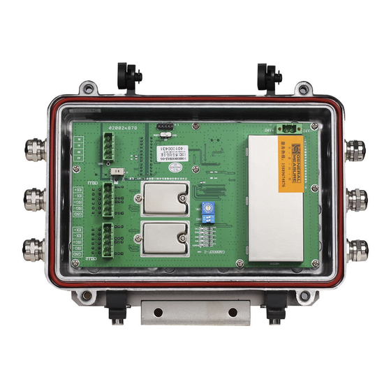
GM8802F-2 Field Mounting Transmitter 1.1 System sketch map A: Se rial port te rminals B、C: load cell connection terminals( Channels 1-2 in turn) . F: Status lights POWER: Power suppl y; Ligh t when powe r on. -
Page 7: Specification
GM8802F-2 Field Mounting Transmitter 1.2 Specification A/D CONVERTER Type 24-bit Delta-Sigma Analogue input range 0mV to 15mV Linearity <0.001%FS Gain Drifting 10PPM/℃ Minimum Sensitivity 0.2 µ V/d Conversion Rate 120/s Display Accuracy 1 / 50,000 CALIBRATION & WEIGHING FUNCTIONS Calibration... -
Page 8: Wiring
GM8802F-2 Field Mounting Transmitter 2 Wiring 2.1 Installation 1. Tighten the screws on hanging mount 2. Loose the screws on transmitter. in suitable place. 3. Fix the transmitter on hanging mount and tighten the screws. GM8802-F2110101... -
Page 9: Power Connection
GM8802F-2 Field Mounting Transmitter 2.2 Power connection GM 8802F-2 Field Mounting Transmitte r co nnects DC24V power supply as follows: P o we r s u p p l y c o n n e c t i o n 2.3 Load cell connection... -
Page 10: Serial Port Connection
GM8802F-2 Field Mounting Transmitter 2.4 Serial port connection GM8802F-2 Field Mounting Transmitter supply 1set of serial port ( RS232/RS485 optional)to communicate with host computer as follows: R S 2 3 2 / R S 4 8 5 s e r i a l p o r ts RS232 connection :... -
Page 11: Theory Instruction
When power on, the POWER light is bright, and then other lights sparkle three times. After testing lights, GM8802F-2 initializes all of parts. When finished, the related Adx(x =1,2)light is bright. If not light, the AD hasn’t finished initialization. Please restart again. If still not light, it means the parts have been damaged. -
Page 12: Parameter Table
GM8802F-2 Field Mounting Transmitter 4 Parameter table Parameters in every channel are same, but also can be set individually. 4.1 Calibrate parameters Parameters Initial values Range Unit 0,1,2,3 Decimal point 0,1,2,3,4 Minimum division 1,2,5,10,20,50 ≤Mini division×50000 Maximum capacity 10000 4.2 Operation parameters... -
Page 13: Serial Port Communication
Default address is 01;default parameters are:baud rate 38400、data format 1-7-E-1、 communication protocol GM-SP1. When user connects more GM8802F-2 by RS485 communication, user should configure different address at first, but for RS232 communication, no need define, use default address When default parameters can’t meet requirement, user should configure serial port communication parameters. -
Page 14: Configuring Communication Parameters
After that, user can define parameters, such as baud rate, data format, communication protocols and so on;when finished, user need dial dip switch D6 to 0(normal) and restart power, so GM8802F-2 begin to communicate data with host computer by update parameters. Define parameters as following fixed protocol: Data format:7bits,1 bit stop,Even(7-E-1)... - Page 15 GM8802F-2 Field Mounting Transmitter 7-E-1 7-O-1 MODBUS-ASCII 7-N-2 Reserve 7-E-1 7-O-1 GM-SP1 7-N-2 8-N-1 DATA4 —— 1bit,high and low byte mode by MODBUS protocol:30H:high byte in the front;31H:low byte in the front. But for GM-SP1 protocol,both of 30H and 31H are available ——...
-
Page 16: Communication Protocols
GM8802F-2 Field Mounting Transmitter 5.2 Communication protocols GM8802F-4 support thress protocols: GM-SP1,Modbus RTU and ASCII. 5.2.1 GM-SP1 protocol Data format:7bits,1bit stop,even(7-E-1) 7 bits,1 bit stop,odd(7-O-1) 7 bits,2 bit stop,none(7-N-2) 8 bits,1 bit stop,none(8-N-1) Baud rate:9600、19200、38400、57600(optional) Code:ASCII Operation code:W,write;R,read;C,calibration;O,Option. CRC check sum: Add all of front digits and convert to decimal system, then take the last two bits to convert to ASCII(tens digit in the front and unit's digit at back). -
Page 17: Read Operatioin
GM8802F-2 Field Mounting Transmitter (The Return transmitter mode: 02F2 Transmitter mode channel no. must be A) Zero calibration with weights Zero calibration without weights Gain calibration with weights Gain calibration without weights Zeroing operation Start/shut AD EN/DI operation Restart system The channel no. - Page 18 GM8802F-2 Field Mounting Transmitter For example Read command from address 01 in channel no. 1:02 30 31 31 52 57 54 30 31 0D 0A Correct response: 02 30 31 31 52 57 54 40 61 30 30 30 31 33 32 35 36 0D 0A Means:AD start、normal、positive weight、nonzero、stable;weight:132...
-
Page 19: Write Operation
GM8802F-2 Field Mounting Transmitter 5.2.1.3 Write operation 1)Write maximum capacity and minimum division Read command: Mini Address Channel no. W CRC CR division capacity Correct response: Address Channel no. W Here: —— 1bit,57H —— 1 bit,44H —— 1 bit,43H Minimum division —— 2 bits,write value: 01/02/05/10/20/50(30H 31H~35H 30H)... -
Page 20: Calibration
GM8802F-2 Field Mounting Transmitter 5.2.1.4 Calibration 1)Zero calibration with weights Note: Write command to calibrate zero when system is stable. Calibration command: Address Channel no. Correct response: Address Channel no. Here: C —— 1bit,43H Z —— 1bit,5AH Y —— 1bit,59H For example: Calibrate zero on address 01 in channel no. - Page 21 GM8802F-2 Field Mounting Transmitter 1) Zero calibration without weights Note: Calibration without weights is only for urgency. If change new load cells or indicator, or adjust weighing system, the calibration is not correct. Calibration command: Address Channel no. Zero millivolt Correct response:...
-
Page 22: Optional Operation
GM8802F-2 Field Mounting Transmitter 5.2.1.5 Optional operation Optional command: Address Channel no. Parameter code Correct response: Address Channel no. Parameter code Here: —— 1bit,4FH Parameter code —— 2bit,Please refer Character 5.2.1.1“Parameter code table” For example: Zeroing on address 01 in channel no. 1: Optional command:02 30 31 31 4F 43 5A 38 34 0D 0A... -
Page 23: Modbus Communication
GM8802F-2 Field Mounting Transmitter 5.2.2 Modbus communication 5.2.2.1Modbus address Communication Defination Description address address Four bytes and only read address(function code:03) Four bytes including sign When AD is error: 0x7F455252(low 3bits is E,R,R) 40001 0000 Weight from channel no. 1 When AD shut:... - Page 24 GM8802F-2 Field Mounting Transmitter 40021 0020 Reserved bit Fixed data:0x7F+'R'+'E'+'V' 40023 0022 Reserved bit Channel no. 1 sign: bit0:0 unstable / 1 stable bit1:0 normal / 1 overflow bit2:0 nonezero / 1 zero bit3:0 positive sign / 1 minus sign bit4:0 AD normal / 1 AD error...
- Page 25 GM8802F-2 Field Mounting Transmitter Channel no. 2 40114 0113 zero-tracking range Channel no. 2 40115 0114 zero-tracking range Channel no. 2 zeroing 40116 0115 range Channel no. 2 unit 40117 0116 Channel no. 2 deciaml 40118 0117 digits Channel no. 2 minimum...
- Page 26 GM8802F-2 Field Mounting Transmitter Channel no.2 zero Write zero millivolt value; Read zero 40219 0218 calibration without weights millivolt value. Write gain millivolt when Write both of command to finish Channel no.2 gain calibration 40221 0220 grain calibration; without weights...
- Page 27 GM8802F-2 Field Mounting Transmitter Write operation:Ineffective, and Reserve return error message. 0404 0403 Read operation:read fixed 0 Write:ON for zero calibration OFF for no operation. Channel no.1 zeroing 0405 0404 Read:1 for zero status 0 for nonezero status Write:ON for zero calibration OFF for no operation.
-
Page 28: Function Code
GM8802F-2 Field Mounting Transmitter 5.2.2.2Modbus communication mode RTU mode (1)every 8-bit byte(1 byte) are divided into 2pcs of 4-bit hexadecimal characters to transmit. (2)The alternate space of every string need more than 3.5pcs characters. Suggest using more than 4pcs characters as alternate space to ensure reliable end. - Page 29 GM8802F-2 Field Mounting Transmitter Correct response: CRC parity Data format: Address Function Counting Data code byte Bytes: Inquiry command:01 01 01 2C 00 04 FD FC Correct response:01 01 01 01 90 48(Coil 0303-0300 related state:0-0-0-1) 2)ASCII mode: Inquiry command:...
- Page 30 GM8802F-2 Field Mounting Transmitter 2)ASCII mode: Inquiry command: Data format: Start Inquiry Address Function Start register parity code address quantity Characters: Correct response: Data format: Start Register Register Addres Functi (0100) (0101) nting parit byte data data code Characters: Inquiry command: 3A 30 31 30 33 30 30 36 34 30 30 30 32 39 36 0D 0A Correct response:3A 30 31 30 33 30 34 30 30 30 35 30 30 30 35 45 45 0D 0A(register...
- Page 31 GM8802F-2 Field Mounting Transmitter Correct response: Data format: Start Coil Force data Address Function address parity code Characters: Inquiry command:3A 30 31 30 35 30 31 39 41 46 46 30 30 36 30 0D 0A Correct response:3A 30 31 30 35 30 31 39 41 46 46 30 30 36 30 0D 0A(Coil 0410 have been in ON state)...
-
Page 32: Error Communication Message
GM8802F-2 Field Mounting Transmitter Inquiry:Regulate to preset register start address and preset value. Response:Return address, function code, start address and preset register quantity. For example:Preset 2 registers in address 01: start register is 0200. Preset value is 0001H and 7318H 1)RTU mode:... -
Page 33: Dimension
Error parity in receiving data. Note: Return Error parity the code when CRC/LRC is error. The data format of error message from GM8802F-2 to host computer as follows: 1)RTU mode: Data format: Address... - Page 34 GM8802F-2 Field Mounting Transmitter GM8802-F2110101...
-
Page 35: Hanging Mount And Hole Size
GM8802F-2 Field Mounting Transmitter 6.2 Hanging mount and hole size: GM8802-F2110101...
Need help?
Do you have a question about the GM8802F-2 and is the answer not in the manual?
Questions and answers