Advertisement
Quick Links
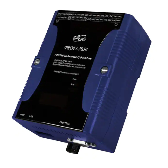
PROFIBUS Remote I/O Module
Introduction
This user guide introduces the user how to implement the PROFI-5000
into their applications in a quick and easy way. Therefore, it only provides
the basic instructions. For more detail information about the PROFI -5000
module, please refer to the PROFI-5000 user manual in the ICP DAS
product CD or download it from ICP DAS web site.
PROFI-5000 Connector and Pin Assignment
The PROFIBUS connector is a standard 9 -pin D-Sub connector, there are
only 4 pins used in PROFI-5000. The pins VP and GND support the 5 volt
power to active terminal resistor, and the A-Line and B-Line is the data bus.
Status Indicator
PROFI-5045/ PROFI-5050/ PROFI-5051/ PROFI-
5052/ PROFI-5053/ PROFI-5055/ PROFI-5060
It provides two types of status indicator, they are PWR
LED (Red) and RUN LED (Green).
Status Indicator
PWR ON
&
RUN OFF
PROFI-5053 PROFIBUS DAQ Module - QuickStart (Apr/2017)
ICP DAS USA, Inc. |
www.icpdas-usa.com
PROFI-5053
Quick Start Guide
Pin No.
Signal
3
B-Line
5
GND
6
VP
8
A-Line
Meaning
Master not Ready,
Address not Match
or
Cfg Fault
| 1-310-517-9888 | 24309 Narbonne Ave. Suite 200. Lomita, CA 90717
Meaning
Receive/Transmit data – plus
Power ground of active terminator
Power 5 volt of active terminator
Receive/Transmit data - minus
Recommend solution
1. Check the address setting
of module and DP-master.
2. Sets the DP-Master to
operation mode.
3. Make sure of the
consistency of Module
Selection.
1
Advertisement

Related Manuals for ICP DAS USA PROFI-5045


Summary of Contents for ICP DAS USA PROFI-5045
- Page 1 4 pins used in PROFI-5000. The pins VP and GND support the 5 volt power to active terminal resistor, and the A-Line and B-Line is the data bus. Status Indicator PROFI-5045/ PROFI-5050/ PROFI-5051/ PROFI- 5052/ PROFI-5053/ PROFI-5055/ PROFI-5060 It provides two types of status indicator, they are PWR LED (Red) and RUN LED (Green).
- Page 2 Check the Input/Output value ERR Flash (Diag. Msg. that if exceed/under the limit lnterlace(0.5 sec) Request) PROFI-5053 PROFIBUS DAQ Module - QuickStart (Apr/2017) ICP DAS USA, Inc. | www.icpdas-usa.com | 1-310-517-9888 | 24309 Narbonne Ave. Suite 200. Lomita, CA 90717...
-
Page 3: Terminating Resistors
126 is a special address that supports the remote setting SSA telegram from Class 2 DP-Master. PROFI-5045/ PROFI-5050/ PROFI-5051/ PROFI-5052/ PROFI-5053/ PROFI-5055/ PROFI-5060 PROFI-5053 PROFIBUS DAQ Module - QuickStart (Apr/2017) ICP DAS USA, Inc. | www.icpdas-usa.com | 1-310-517-9888 | 24309 Narbonne Ave. Suite 200. Lomita, CA 90717... - Page 4 EX 1 : MSB = 0, LSB = B, node address => (0*16+11) = 11 EX 2 : MSB =7, LSB = 9, node address => (7*16+9) = 121 PROFI-5053 PROFIBUS DAQ Module - QuickStart (Apr/2017) ICP DAS USA, Inc. | www.icpdas-usa.com | 1-310-517-9888 | 24309 Narbonne Ave. Suite 200. Lomita, CA 90717...
- Page 5 Select Option -> Install GSD files c. Click “Browse” to select GSD file, and then click “Install” PROFI-5053 PROFIBUS DAQ Module - QuickStart (Apr/2017) ICP DAS USA, Inc. | www.icpdas-usa.com | 1-310-517-9888 | 24309 Narbonne Ave. Suite 200. Lomita, CA 90717...
- Page 6 3. Select I/O modules a. Choose PROFI-5000 b. add I/O module that you want to use. PROFI-5053 PROFIBUS DAQ Module - QuickStart (Apr/2017) ICP DAS USA, Inc. | www.icpdas-usa.com | 1-310-517-9888 | 24309 Narbonne Ave. Suite 200. Lomita, CA 90717...
- Page 7 Users load the setting and program into DP-Master, and let it go. a. Select Station -> Save and Compile PROFI-5053 PROFIBUS DAQ Module - QuickStart (Apr/2017) ICP DAS USA, Inc. | www.icpdas-usa.com | 1-310-517-9888 | 24309 Narbonne Ave. Suite 200. Lomita, CA 90717...
- Page 8 After the procedure finish, DP-Master will establish the connection with PROFI-5000 and execute program automatically. RUN_LED indicates the status of connection that you can observe. PROFI-5053 PROFIBUS DAQ Module - QuickStart (Apr/2017) ICP DAS USA, Inc. | www.icpdas-usa.com | 1-310-517-9888 | 24309 Narbonne Ave. Suite 200. Lomita, CA 90717...
- Page 9 PROFI-5000 Quick Start (Version 2.1, June/2013) ------8 PROFI-5053 PROFIBUS DAQ Module - QuickStart (Apr/2017) ICP DAS USA, Inc. | www.icpdas-usa.com | 1-310-517-9888 | 24309 Narbonne Ave. Suite 200. Lomita, CA 90717...
Need help?
Do you have a question about the PROFI-5045 and is the answer not in the manual?
Questions and answers