ICP DAS USA PM-3133-RCT Quick Start Manual
Hide thumbs
Also See for PM-3133-RCT:
- User manual (69 pages) ,
- User manual (72 pages) ,
- Quick start manual (8 pages)
Table of Contents
Advertisement
Quick Links
1. Packing List
This shipping package contains the following items
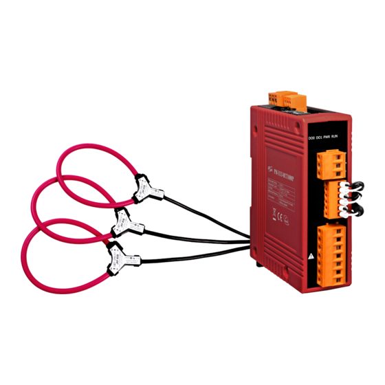
1 x PM-3133-RCT module 1 x Quick Start Screw Driver x 1 Cable ties x 3
1.1. Caution & Warning
result in serious injury or death. Any work on or near energized meters,
meter sockets, or other metering equipment could induce a danger of
electrical shock. It is strongly recommended that all work should be
performed only by qualified industrial electricians and metering
specialist. ICP DAS assumes no responsibility if your electrical installer
does not follow the appropriate national and local electrical codes.
ICP DAS assumes no liability for any damage resulting from the use of
this product. ICP DAS reserves the right to change this manual at any
time without notice.
The meter contains hazardous voltages, and should
never be disassembled. Failing to follow this practice will
PM-3133-RCT Quick Start
v1.4, June 2020
Advertisement
Table of Contents

Related Manuals for ICP DAS USA PM-3133-RCT


Summary of Contents for ICP DAS USA PM-3133-RCT
- Page 1 June 2020 1. Packing List This shipping package contains the following items 1 x PM-3133-RCT module 1 x Quick Start Screw Driver x 1 Cable ties x 3 1.1. Caution & Warning The meter contains hazardous voltages, and should never be disassembled.
- Page 2 1.2 Resources How to search for drivers, manuals and Technical Support spec information on ICP DAS website. service@icpdas.com For Mobile Web www.icpdas.com Model Name For Desktop Web Model Name 2. Installation 2.1. Products come with external split type clip-on CT’s. Disconnect the CT’s or use other CT’s is highly prohibited.
- Page 3 2.2. Voltage Input 1. PM-3133 series: Input Voltage up to 500V. For any higher Input Voltage large than 500V, please add the PT (power transformer), and Change PT RATIO setup. 2. Confirm the RST (ABC) phase sequence. 2.3. Connection Please firstly check the current input terminal, and then in white black, white black, white black wire sequences (CT1-P1, CT1-P2, CT2-P1, CT2-P2, CT3-P1, CT3-P2).
- Page 4 2.4. Positional Accuracy 1. -500P: W Accuracy Better than 2% (PF=1; Input Current >50A; the “A” area). -1000P: W Accuracy Better than 2% (PF=1; Input Current >50A; the “A” area). -2000P: W Accuracy Better than 2% (PF=1; Input Current >50A; the “A” area). -4000P: W Accuracy Better than 2% (PF=1;...
- Page 5 Type 1 CT’s installation steps: Type 2 CT’s installation steps:...
- Page 6 2.5. Wiring 1P2W-1CT(PM-3133) 1P3W-2CT(PM-3133)
- Page 7 3P3W-3CT(PM-3133) 3P4W-3CT(PM-3133)
- Page 8 Communication 3.1. RS-485 & CAN setting Default setting for RS-485: 19200, n, 8, 1 ,for CAN: 125K bps DIP switch (SW1-SW6) is used for Modbus address(or CANopen Node ID) setting, default is 1, i.e. all OFF For example: Modbus address(or CANopen Node ID) is 10, find the table of DIP switch 1-6 is ON, OFF, OFF, ON, OFF, OFF ...
Need help?
Do you have a question about the PM-3133-RCT and is the answer not in the manual?
Questions and answers