Panasonic KXF-193C Operating Manual
Screen printer
Hide thumbs
Also See for KXF-193C:
- Operating instructions manual (62 pages) ,
- Operating instructions manual (120 pages)
Table of Contents
Advertisement
Quick Links
Screen Printer SP22P
Operating Instructions
K X F - 1 9 3 C
Model No.
Operating Manual
(Engineers)
Thank you for purchasing SP22P, the screen printer.
Before placing the machine in service, be sure to read the instruction manual for
proper usage.
After that, store it carefully and it if necessary.
193C-E-EMAB-0002
Advertisement
Table of Contents

Related Manuals for Panasonic KXF-193C


Summary of Contents for Panasonic KXF-193C
- Page 1 Screen Printer SP22P Operating Instructions K X F - 1 9 3 C Model No. Operating Manual (Engineers) Thank you for purchasing SP22P, the screen printer. Before placing the machine in service, be sure to read the instruction manual for proper usage.
- Page 3 WARNING DO NOT ALLOW ANY PERSON WHO HAS NOT RECEIVED SPECIAL TRAINING TO OPERATE THE MACHINE. The machine may be operated improperly and injure you. Either carry out training by yourself, or consult the manufacturer. M11E 193C-E-EMA00-B01-00 Page 3...
- Page 4 ORGANIZATION OF MANUALS 4 manuals are attached to this machine. They are classified into 4 types. Use each manual according to the working purpose and person in charge. The production data of the line including this machine are programmed on PT. Refer to the instruction manuals accompanied with PT.
- Page 5 Operating Manual Operating Manual O N S C A U T I Y P R E For Engineers M E N T S A F E T E Q U I P N E O F O U T L I T I O N O P E R A N B O A R D...
-
Page 6: Table Of Contents
SAFETY PRECAUTIONS ..............11 OUTLINE OF EQUIPMENT Chapter Characteristics of Machine ................. 1-2 1-1-1 High-speed and High Accuracy Printing ............. 1-2 1-1-2 High Quality Printing ................... 1-2 1-1-3 New Type of Cleaning Unit .................. 1-3 1-1-4 Storing the Solder Paste ..................1-3 1-1-5 Improved Operation .................... - Page 7 Adjusting the Board Clamp Force ............3-12 Setting the Board Holder (Optional) ............3-13 Checking Solder and Print Condition Data ..........3-14 Board Transfer Test ................... 3-16 Changing Squeegees ................3-18 Setting the Mask ..................3-22 3-10 Automatic Print Pressure Teaching............3-24 3-11 Checking the Printing by Printing Test ............
- Page 8 4-10 Printing Position Data ................4-39 4-10-1 Printing Position Data ..................4-39 4-11 Data Check ....................4-40 4-11-1 Data Check .......................4-40 4-11-2 Executing Data Check ..................4-40 4-12 Function Switch ..................4-41 4-12-1 Function Switch ....................4-41 4-12-2 Setting Function Switch ..................4-42 4-13 Form Printing ....................
- Page 9 FILE OPERATION Chapter File Operation of PT100 ................6-2 6-1-1 Loading Data ....................... 6-3 File Operation of Floppy Disk ..............6-5 6-2-1 Loading Data ....................... 6-6 6-2-2 Saving Data ......................6-8 6-2-3 Loading and Saving the Machine Parameter ............ 6-11 6-2-4 Loading Coordinate Data ..................
- Page 10 INDEX RECOGNITION DEVICE Appendix Page 10 193C-E-EMA00-A02-01...
-
Page 11: Safety Precautions
SAFETY PRECAUTIONS Be sure to observe The precautions that must be observed in order to prevent injury to the user or another person, or damage to property, are as follows. The degree of danger or injury resulting from incorrect use due to failure to read an indica- tion is classified and described as follows. - Page 12 SAFETY PRECAUTIONS Be sure to observe WARNING Follow the warning indication. This is a label for ensuring the safe machine use. If you do not observe it, there is a risk of human injury or damage to property. The following warning labels are pasted on this machine. Follow the instructions on each label. If a label has come off, put a new one on a proper position.
- Page 13 SAFETY PRECAUTIONS Be sure to observe WARNING Rear view of warning label attached positions DANGER DO NOT OPEN THE COVER WHEN OPERATING You will have serious injury if you touch the active part inside. 0 1 K 1 B WARNING DO NOT DISABLE SAFETY SENSOR You will have serious...
- Page 14 SAFETY PRECAUTIONS Be sure to observe WARNING If you sense any danger or abnormality, press an emergency stop button to stop the machine. If you continue to operate the machine in a dangerous or abnormal state, a breakdown or an accident will occur.
- Page 15 SAFETY PRECAUTIONS Be sure to observe WARNING Observe the following items before placing your hand or other part of your body in an active part of the machine in order to feed production material, change machine set-up, or adjust machine settings. You may be injured if the machine is actuated.
- Page 16 SAFETY PRECAUTIONS Be sure to observe DANGER DO NOT OPEN THE COVER WHEN OPER- ATING. You will have serious injury if you touch the active part inside. L06EB Page 16 193C-E-EMA00-A03-00...
- Page 17 SAFETY PRECAUTIONS Be sure to observe WARNING DO NOT DISABLE HIGH VOLTAGE. NO OPEN FLAME. SAFETY SENSOR. You will have serious injury by active part if you disable safety You will have serious electric Solvent may catch fire. sensor. shock if you touch electric power supply inside.
- Page 18 SAFETY PRECAUTIONS Be sure to observe WARNING DO NOT PLACE YOUR HANDS OR ONLY THE PERSON IN CHARGE OF BODY INSIDE ACTIVE PART OF THE MAINTENANCE MUST REPAIR OR MACHINE WHEN IT IS IN A SINGLE ADJUST THE MACHINE. STOP OR CYCLE STOP CONDITION. The machine may be incorrectly repaired or ad- justed, resulting in malfunction.
- Page 19 SAFETY PRECAUTIONS Be sure to observe WARNING DO NOT DAMAGE POWER AND PERIODICALLY REMOVE DUST OTHER CORDS OR PLUGS. FROM POWER PLUG. Never damage, remake, bring close to heating appliances, bend forcibly, twist, pull, put heavy objects on, and bundle up. Damaged cord and plug may cause electric shock, Dust on the plug may result in fire caused by short circuit or fire.
- Page 20 SAFETY PRECAUTIONS Be sure to observe CAUTION DO NOT PLACE ANY BE CAREFUL WITH IPA (ISOPROPYL AL- COHOL) USE ONLY. OBJECT AROUND YOUR HANDS AND EMERGENCY STOP FINGERS WHEN BUTTONS. CLOSING THE COVER. The corrosion damage to the You will be unable to press a Your hands or fingers may be hose may cause the machine to button to stop the machine in...
- Page 21 SAFETY PRECAUTIONS Be sure to observe CAUTION TURN ON THE USE A JIG TO FIT AND DO NOT GIVE A POWER BEFORE REMOVE THE SHOCK TO THE ELEC- SUPPLYING AIR. SPRINGS. TRICAL EQUIPMENTS. Your hands or fingers may be Your hands or fingers may be There is a risk of an electric caught in the board support.
- Page 22 SAFETY PRECAUTIONS Be sure to observe CAUTION BE CAREFUL IN HAN- DLING IPA (ISOPRO- PYL ALCOHOL). Isopropyl alcohol is harmful to the human body. Wear the mask to avoid organic odor when using isopropyl alcohol. M84EB Page 22 193C-E-EMA00-A03-00...
- Page 23 SAFETY PRECAUTIONS Be sure to observe About Interlock About Safety Cover Interlock 1. Basic feature of safety cover interlock Before starting regular automatic production on this machine, close all safety covers. Since a screen displays the message prompting you to supply a member when it needs to be supplied, open the corresponding cover according to the member to be supplied and then conduct the work.
- Page 24 CLEANING SOLVENT FOR WET CLEANING Ethyl alcohol Recommended rate of mixed cleaning solvent : IPA (Isopropyl alcohol) Considering cleaning results, costs, availability, etc., IPA is recommended. (However, handle IPA with great care because it may catch fire.) Even if the IPA concentration is diluted to 4% by ethyl alcohol, the successful cleaning result can still be obtained.
- Page 25 CLEANING SOLVENT FOR WET CLEANING ∗ However, the cleaning result gets worse. Besides, it takes more time for the mask to dry, so set the cleaning speed to 10mm/s for Back of the second cleaning. 153C-E-TE008 Optimum discharge amount of cleaning solvent for cleaning It is optimum to discharge the 35mm ±...
- Page 26 ABOUT DISPOSAL OF COMPONENTS CONTAINING MERCURY NOTICE This product has a fluorescent lamp that contains a small amount of mercury. It also contains lead in some components. Disposal of these materials may be regulated in your community due to environmental considerations. For disposal or recycling information please contact your local authorities, or the Electronics Industries Alliance.
- Page 27 IDENTITY PLATE AND CAUTION LABEL Both an identity plate and a caution label for this product are attached to the machine. Operate and maintain the machine according to the instructions on the label. ∗1 : Nameplates on X-Y table are for maintaining machine’s accuracy. 193C-AE00 X-Y table ∗1...
- Page 28 HANDLING FLOPPY DISK Data and program for this machine, basically managed by PT100, are saved to and loaded from a floppy disk. This section describes the protection and han- dling of such floppy disks. NOTICE Only 3.5-inch 2DD floppy disks can be used for this machine. 2HD disks cannot be used.
- Page 29 HANDLING FLOPPY DISK Precautions for Handling Disks CAUTION OBSERVE THE FOLLOWING ITEMS WHEN HANDLING FLOPPY DISKS. Floppy disks and the data in them can be destroyed. M37E Do not bring a magnet close to the Do not attach a new label over an old one. disk.
- Page 30 SERIAL PLATE The serial plate attached to this machine indicates the model name and production number. SP22P-M KXF-193C 193C-AB00 Actual numbers are shown on the plate instead of ∗. Page 30 193C-E-EMA00-A04-03...
- Page 31 HOW TO SEE DESCRIPTION FOR OPERATION The description depends on each page, but basic structure is as follows. T i t l e T i t l e 1-1-1 Starting Production 1. Press Actual operation Actual operation Production • “Return to origin” for all axes are carried out. Operating procedure number Operating procedure number Supplementary description on operation...
- Page 32 = MEMO = 193C-E-EMA00-A04-01 Page 32...
-
Page 33: Outline Of Equipment
Chapter OUTLINE OF EQUIPMENT OUTLINE OF EQUIPMENT SP22P-M SP22P-M is the high quality screen printer which achieved the high-speed and high quality printing, and easy machine change. The new type of cleaning unit and digital head with feedback function enables the high quality printing under the best condition. -
Page 34: Characteristics Of Machine
Characteristics of Machine 1-1-1 High-speed and High Accuracy Printing Improving the structure and making the X-Y table high-speed reduced the board transfer time greatly, effecting to the printing tact (including board recognition) to 50 % to 60 % of general printer. -
Page 35: New Type Of Cleaning Unit
Characteristics of Machine 1-1-3 New Type of Cleaning Unit By combining 1- and 2- round cleaning, wet and dry, and setting the vacuum ON / OFF, the best cleaning for each characteristic of solder is carried out. Mask Screen mask Wit nozzle Moving direction... -
Page 36: Improved Operation
Characteristics of Machine 1-1-5 Improved Operation The adoption of the LCD color touch panel on the operating part offers very clear vision. Also it makes easy to exchange Japanese and English. Tree jump function The specified screen appears on any screen by using this, saving time. Layered operation The improper operation is reduced to a minimum by classifying the operating screens into each mode for the operator and engineer. -
Page 37: Movement Principle (Mechanism Of Printing)
Movement Principle (Mechanism of Printing) This printer, with the front and rear squeegees, piles masks on the board and fill up the solder paste to the mask opening, then duplicates the solder on the board. Mask ○ ○ ○ ○ ○... -
Page 38: Specifications Of Device
Specifications of Device 1-3-1 Specifications of Machine ∗ × 5 × 0 × 0 × 0 – – – N o t × 0 × 0 – – ± ° t i s ± t I ( ± ± e l l y t i ×... -
Page 39: Dead Space
Specifications of Device 1-3-2 Dead Space Board Fixed side Space for transferring 193C-053E 1-3-3 Board Flow Direction Fixed side Reference Board flow direction Automatic width adjustment Operator 193C-054E 193C-E-EMA01-A01-00 Page 1-7... -
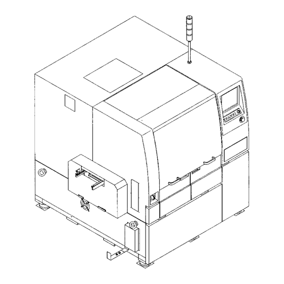
Page 40: Outer Size
Specifications of Device 1-3-4 Outer Size Board flow direction Fixed side X-Y table 193C-055E Adjustment bolt Board transfer height 1400 1900 193C-056E 193C-E-EMA01-A01-00 Page 1-8... -
Page 41: Other Specifications
Other Specifications 1-4-1 Specifications of Board Items Specifications 50 mm ≤ L ≤ 330 mm Board size 50 mm ≤ W ≤ 250 mm Transfer direction 0.4 mm ≤ H ≤ 3.0 mm Max.: 330 mm (L) × 250 mm (W) Min. -
Page 42: Accessories And Spares
Accessories and Spares Following accessories and spares are attached to this machine in addition to the main body. c t i g i j l l a l l a t s i l l o 193C-E-EMA01-A01-00 Page 1-10... -
Page 43: Main Option
Main Option Atmosphere control unit Items Contents Blowing duct Filter Operation panel Drain tank (internal organ type) Main body e i l l i t n i l l i b y t i l l e e l l t l i f 2 °... - Page 44 Main Option Others (1/2) Items Appearance 100 of support pins are attached Matrix plate Pickup block Board holder unit Flat squeegee holder for narrow pitch L=270, 220 170 mm, others Dagger squeegee holder L=350, 270 170 mm, others Square squeegee holder L=350 mm For ceramic board Set the shutter for board recognition camera.
- Page 45 Main Option (2/2) Items Appearance Squeegee head setting board Digital head Temporal type of automatic solder paste supply unit Squeegee Syringe 193C-066E Mask cleaning unit for small frame 193C-067E 193C-E-EMA01-A01-00 Page 1-13...
- Page 46 = MEMO = 193C-E-EMA01-A01-01 Page 1-14...
-
Page 47: Basic Operation
Chapter BASIC OPERATION BASIC OPERATION Engineer Mode The functions of touch panel are divided into the operator and engineer modes up to its purpose, to prevent wrong operation. This section describes the main menu for the engineer mode. (See the manual for operators, for the menu and operation switches under the screen for the operator mode.) Main menu of engineer mode 193C-E-EMA02-A01-00... -
Page 48: Functions Of Engineer Mode
Functions of Engineer Mode 2-1-1 Entering the Engineer Mode ∗ The password is required to enter the engineer mode. If the password is not set, see “2-1-4 Changing Passwords,” and set it. . Press Engineer • The password input screen appears. 3Y3C-EOP-Main-001 . -
Page 49: Functions Of The Main Menu
Functions of Engineer Mode 2-1-2 Functions of the Main Menu Pressing the icon switch in the main menu enables to open that operating menu. • Pressing displays the main menu for the operator mode. Check period indication blank • When the period for the daily check comes near (90% of cycle is over), the message in yellow appears. -
Page 50: Menu Tree Functions
Functions of the Engineer Mode 2-1-3 Menu Tree Functions Following menu tree appears on any screens by pressing the key. Pressing the icon switch on the menu tree opens that operating menu. 193C-EEn-PrIs-001 193C-EEn-MaAi-001 193C-EEn-Mp-001 Press the key under the screen. Press the icon. -
Page 51: Changing Passwords
Functions of Engineer Mode 2-1-4 Changing Passwords ∗ The key floppy disk for changing passwords is required for changing (setting) it. . Set the key floppy disk for changing passwords into the disk drive. . Press on the main menu for the Engineer operator mode. -
Page 52: Functions During Production Stop
Functions during Production Stop These are functions to make an immediate stop during production. (The immediate stop is to stop the production shortly during the sequence.) WARNING DO NOT PLACE YOUR HANDS OR BODY INSIDE ACTIVE PART OF THE MA- CHINE WHEN IT IS IN A SINGLE STOP OR CYCLE STOP CONDITION. -
Page 53: Maintenance
Functions during Production Stop 2-2-1 Maintenance 1. Press Maintenance . • The maintenance for the automatic operation is carried out. Squeegee open and close : Squeegee open and close screen appears. See “7-10 Squeegee Open and Close.” Cleaning 1 round : 1-round mask cleaning is carried out. -
Page 54: Data Input Operation
Data Input Operation Following two ways are available for the data input operation. a) Using the cursor key Press the cursor key. • The highlighted part moves. Enter numerals with numeral keys. • If the wrong numeral is entered, press BS to reenter. -
Page 55: Changing Production Boards
Chapter CHANGING CHANGING PRODUCTION BOARDS PRODUCTION BOARDS Changing Production Boards To print the solder on the different board from the former one, it is necessary to adjust the device for the board and supply production materials. This section describes the changing operation of production boards, taking data of production board on PT100. -
Page 56: Changing Production Data
Changing Production Data This section describes loading data from PT as an example. To load data from PT100, two ways of “a) Transferring from PT100 to this machine” and “b) Loading by file operation” are available. • To load data of the floppy disk, see “Chapter 6 File Operation.” ∗... - Page 57 Changing Production Data b) Loading by file operation . Press File managment • The file operation screen appears. . Press PT100 . • Change the device object to PT100. ∗ To display data of PT100 by this machine, it is necessary to register in the list on PT100.
- Page 58 Changing Production Data . Select the data name to load. • The selected data name is highlighted. . Press Yes . • Loading data starts. ∗ To quit loading data, press No . • The message “Loading data” appears. • When loading ends, the data name on the right of screen changes to the loaded data name.
-
Page 59: Board Positioning And Adjusting The Lift And Rail Width
Board Positioning and Adjusting the Lift and Rail Width WARNING TAKE CARE NOT TO PINCH YOUR HANDS OR FINGERS. You will have serious injury if your hands or fingers are caught in the conveyors during manual (or automatic) width adjustment. M09E CAUTION BEFORE PERFORMING AUTOMATIC WIDTH ADJUSTMENT, BE SURE TO... -
Page 60: Removing The Board Under Holder
Positioning and Lift Transfer Rail Width Adjustment 3-2-1 Removing the Board Under Holder Remove the board under holder for width adjustment at fast. Check the X-Y table at the origin. If it is not there, return to the machine adjustment and carry out the returning to origin. -
Page 61: Rail Width Adjustment
Positioning and Lift Transfer Rail Width Adjustment 3-2-2 Rail Width Adjustment The rail width of front and rear transfer conveyors and board holder are automatically adjusted. Turn on the servo switch. SERVO OFF ( ) ON ( Press Machine adjust •... - Page 62 Positioning and Lift Transfer Rail Width Adjustment UNLOCK Press and Width adjust . • The width adjustment screen appears. UNLOCK Press and Run . • The width is adjusted for the set board. • “Conveyor width adjust preparing” The message “Conveyor width adjusting” appears, and the transfer rail is automatically adjusted.
-
Page 63: Setting The Board Under Holder Plate On The Movable Side
Positioning and Lift Transfer Rail Width Adjustment 3-2-3 Setting the Board Under Holder Plate on the Movable Side Set the board under holder plate on the movable side which is removed at the procedure 3-2-1. Turn off the servo switch. SERVO OFF ( ) ON (... -
Page 64: Setting The Board Under Holder
Setting the Board Under Holder WARNING TURN OFF THE POWER AND THE SERVO SWITCH BEFORE WORKING INSIDE ACTIVE PART OF THE MACHINE FOR MACHINE SET-UP. You will have serious injury if the machine is actuated. M45EB The following three types are available for the board under holder, and the under holder set de- pends upon each board type. - Page 65 Setting the Board Under Holder Insert the support pin to the matrix Board support pin plate so as they get the board equally. • If the mount part is on the back side of board, insert it not to touch to other thing. Matrix plate b) Setting the board under holder block Block for fixed side...
-
Page 66: Adjusting The Board Clamp Force
Adjusting the Board Clamp Force The board clamp force (force to fix the board) is adjusted according to the shape and quality of board. Regulator knob for Turn the regulator knob for the board board clamp clamp to adjust. • Pull up the knob upward and turn it. After adjustment, push it down. -
Page 67: Setting The Board Holder (Optional)
Setting the Board Holder (Optional) The board holder unit is used when the board to print is thin or having warp. Adjust the interval between board holder bars according to the board size. Loosen this screw and adjust the interval between board holder bars. -
Page 68: Checking Solder And Print Condition Data
Checking Solder and Print Condition Data For the automatic solder supply as an option, check that the set solder matches to that in the print condition data in following procedures. Press Data modify • The data modification menu screen appears. Press Form print . - Page 69 Checking Solder and Print Condition Data Check that the solder of form YYYY-MM-DD (∗) HH:MM:SS Data : CREATE matches to the actual one. ∗∗∗∗ Print cond data ∗∗∗∗ F[mm/s] R[mm/s] WaitPrnt Pressure F Pressure R Length 0.00 10.000 18.000 350.000 Squeegee Act mode : Single Kind...
-
Page 70: Board Transfer Test
Board Transfer Test After adjusting the board rail width and support pins, the board transfer test is carried out on the board transfer screen. The board transfer end position blinks as Carry in → Load → Unload → Carry out and on the screen during board transferring. NOTICE Actually, the transfer test for whole line is carried out. - Page 71 Board Transfer Test UNLOCK Press and Carry in . • The board is transferred from the pre-station to the front conveyor. UNLOCK Press and Load . • The board is transferred from the front con- veyor to the middle conveyor, and the board positioning is carried out.
-
Page 72: Changing Squeegees
Changing Squeegees Squeegees are changed according to print condition data. Turn on the servo switch. SERVO OFF ( ) ON ( Press Machine adjust • The machine adjustment screen appears. Press Squeegee open/close . • The squeegee open and close screen appears. UNLOCK Press and SQ. - Page 73 Changing Squeegees Turn OFF the servo switch. SERVO OFF ( ) ON ( Knob 1 Loosen the knobs 1 and 2, and re- move the squeegee. • Remove both of F and R squeegees. F squeegee R squeegee 193C-027P Knob 2 Fit the print mark for positioning to the left and right to the edge of holder to set, and tighten the knob 1.
- Page 74 Changing Squeegees Turn ON the servo switch. SERVO OFF ( ) ON ( UNLOCK Press and SQ. close . • The squeegee closes. The angle is displayed by the angle adjustment Loosen the T type knob 2, and turn the knob 3 looking at the angle dis- played on the screen to adjust the angle slightly.
- Page 75 Changing Squeegees Changing Squeegees After adjusting the angle, tighten the T After adjusting the angle, tighten the T type knob 2. type knob 2. T type knob 2 193C-030P Press Press • The machine adjustment menu screen reap- • The machine adjustment menu screen reap- pears.
-
Page 76: Setting The Mask
Setting the Mask The mask for the board to print is set. Turn OFF the servo switch. SERVO ) ON ( OFF ( Set the mask. • Check the board pattern not to set the inner and front masks improperly. 193C-031P Turn ON the servo switch. - Page 77 Setting the Mask Press Data modify • The data modification screen appears. Press Prod data teach . • The production data teaching screen appears. Press Mask / Paste recog . • Carry out mask / solder recognition teaching. See “5-3 Mask / Solder Recognition Teaching” for details.
-
Page 78: Automatic Print Pressure Teaching
3-10 Automatic Print Pressure Teaching Changing squeegees differs the actual print pressure from the setting value, with the changed weight of squeegee. Make sure of the automatic print pressure teaching after changing squeegees. Press Pressure . • The print pressure teaching starts. The switch lights during teaching. -
Page 79: Checking The Printing By Printing Test
3-11 Checking the Printing by Printing Test The printing state is checked by printing test. Press Machine adjust • The machine adjustment menu screen ap- pears. Press Test print . • The test printing mode screen appears. Press Print state check . •... - Page 80 = MEMO = 193C-E-EMA03-A02-01 Page 3-26...
-
Page 81: Data Modification
Chapter DATA MODIFICATION DATA MODIFICATION Data Modification This chapter describes how to edit and create production data. Production data can be edited on PT100 and this machine (only some data can be modified through the data modifying function). ∗ For the PT-less specification, all data can be edited on the machine. 193C-E-EMA04-A01-04 Page 4-1... -
Page 82: Summary Of Data Editing
Summary of Data Editing 4-1-1 Before Data Editing This chapter describes the procedures by using the PT editor screens, except the data that can be modified only on this machine and the operations and screens which are greatly different from those of the PT. - Page 83 Summary of Data Editing PT specification New production data of SP22 are created on PT Filer. SP22 Editor is used to edit these data so that SP22 can use them to print boards. The production data created and edited on the PT are downloaded to SP22, which uses this data to print boards.
-
Page 84: Flow Chart Of Data Editing
Summary of Data Editing 4-1-2 Flow Chart of Data Editing Printing conditions data (Library) 1. Outline of board data When creating new data, set them according (Board data, Recognition data, Positioning to the solder type and the production quality. data) Input the data of the board to be printed. - Page 85 Summary of Data Editing 4. Printing position data Input the difference between the actual printing position and the mask position. When the mask recognition or the batch teaching has been performed, the data are set automatically. When the printing When changing the printing condi- When modifying a part of the conditions data does tions data by using the library...
-
Page 86: Basic Functions Of Editor
Basic Functions of Editor 4-2-1 Starting Editor To start it, double-click on a data file displayed on file information area of the Filer. When starting a new data file, see “4-2-2 Starting New Data File”. 4-2-2 Starting New Data File When you start the Editor of a data file created newly by the Filer, the following screen is displayed. - Page 87 Basic Functions of Editor PatternLibrary When you click on , the registered library data are displayed. When you choose a library data, the contents of the chosen library data and the chosen library data name is displayed in the Refer- ence field.
-
Page 88: Editor Main Menu
Basic Functions of Editor 4-2-3 Editor Main Menu When you start Editor, the following screen is displayed. Menu bar Buttons for each type of data editing Buttons for each type of function Menu bar When you place a pointer on each menu on the menu bar and click on it, its command menu opens. -
Page 89: Structure And Functions Of Menu Bar
Basic Functions of Editor 4-2-4 Structure and Functions of Menu Bar ∗ Each data editing screen Displays the help screen. Sub menu Displays the chosen data editing screen. Used to print each data. Closes each data editing screen or finishes the data editing. 4-2-5 Exiting Editor When you click on Close on the main menu, the following screen is displayed. -
Page 90: Basic Operation For Modifying Data (Sp22)
Basic Operation for Modifying Data (SP22) This section describes the initial step necessary for editing and modifying data on this machine. . Press on the main menu. Data modify • ”Data modify” menu is displayed. • Pressing any button displays that data’s setting screen. -
Page 91: Creating Board Data
Creating Board Data 4-4-1 Board Data 193C-EPt-EdBd-001 1. Board size Enter the size of the board. “L (length)” is the length of the surface parallel to the board transport direction. “W (width)” is the length of the surface vertical to the board transport direction. T (thick- ness)”... -
Page 92: Editing Board Data
Creating Board Data 4-4-2 Editing Board Data Sample board data are input as in the example that follows. . Click on BoardData on the main menu. • [BoardData] sheet on [BoardData] window opens. . Enter the size of the board. ∗... -
Page 93: Creating Board Recognition Data
Creating Board Recognition Data 4-5-1 Board Recognition Data 1. Board recognition mode • Board recognition points AB ....Points A and B are recognized for each board. The devia- tion (∆x, ∆y and ∆θ ) calculated on the basis of the two points is corrected. -
Page 94: Editing Board Recognition Data
Creating Board Recognition Data 4-5-2 Editing Board Recognition Data ∗ When the board recognition motion is disabled in the function switches, you cannot edit. . Click on BoardRecogData . • [BoardRecogData] sheet on [BoardData] window opens. . Enter the coordinates of board recog- nition point A. -
Page 95: Board Positioning Data
Board Positioning Data 4-6-1 Board Positioning Data 1. Y-axis direction clamp motion timing Set the motion timing of the support and the clamp for when the board is fixed. The default is the upper limit. (Except in the case that the other production board data is used) Upper limit DelayTime Board is... -
Page 96: Editing Board Positioning Data
Board Positioning Data 3. Board vacuum motion timing (option) To prevent the board from being moved during board positioning and printing, the vacuum block (option) fixes the board. And setting the vacuum start time and end time decides the timing with the clamp motion. -
Page 97: Mask Data
Mask Data 4-7-1 Mask Data 1. Mask registration No. When registering mask data, input the registration No. and a name that describes it. 2. Mask size Enter the size of mask: Y (length), X (width) and T (thickness). Operator’s side 193C-E-EMA04-A02-00 Page 4-17... - Page 98 Mask Data 3. Plate-making reference Choose the mask plate-making reference according to each condition. Rear Center 550mm (550X650) mask Sample board Longitudinal X-direction center distribution pattern position frame Position of 200mm from the inner standard side of Y-direction mask frame Transport direction (650X550) mask...
- Page 99 Mask Data (160mm) 110mm 550mm Left Rear Sample board (550X650) mask pattern position Position of 110mm from the left edge side of X-direction mask frame Position of 200mm from the inner side of Y-direction mask frame 250mm (650X550) mask Transport Position of 160mm from the left edge 330mm direction...
- Page 100 Mask Data 4. Plate-making reference origin Input the difference between the origin and the mask plate-making reference. 550mm • On the figure on the left, the arrows show a positive xy directions. Positive and negative direction of the difference • The example mask on the left (550 X 650) is made as longitudinal frame standard and rear center reference.
-
Page 101: Editing Mask Data
Mask Data 4-7-2 Editing Mask Data . Click on MaskData . • [MaskData] window opens. . Enter the mask registration No. and name. . Enter the size of the mask. . Choose a plate-making reference. . Enter the Plate-making reference origin. -
Page 102: Mask/Solder Recognition Data
Mask/Solder Recognition Data 4-8-1 Mask/Solder Recognition Data 1. Solder recognition counter 2. Recognition mode 3. Board side/Mask side block data a. Block d. 1 point or 1 pair X b. Solder recognition 1 point or 1 pair Y c. 1 point/1 pair e. - Page 103 Mask/Solder Recognition Data 3. BoardSide/MaskSide Block data The block data for board or mask can be displayed by clicking BoardSide or MaskSide . a. Block It shows each block No. Block 1 and block 2 are used also for mask recognition. So, be sure to set them so that they will be located diagonally and the distance between them should be long.
-
Page 104: Editing Mask/Paste Recognition Data
Mask/Solder Recognition Data 4-8-2 Editing Mask/Paste Recognition Data Click on Mask/Paste Recog . • [Mask/Paste Recog] window opens. . Set the solder recognition counter. • When regarding the check as important : Set the higher number of times. • When regarding the tact time as important : Set the lower number of times. - Page 105 Mask/Solder Recognition Data Input the block data of board side. Set whether to use solder recognition function. Choose 1-point or 1-pair. . Input the coordinates of the recogni- tion point. . Input the next block data by repeating the steps from 5. to 7. Click on DataShift(Board->Mask) .
-
Page 106: Printing Conditions Data
Printing Conditions Data 4-9-1 Printing Conditions Data 1. Squeegee a. Motion mode Choose 1-round printing motion (Single) or 2-round printing motion (Double). b. Priority After Printing Set which should move first after printing, lift, squeegee or both together. Lift : The squeegee is fixed and the mask is released while the squeegee is down. After that, the squeegee rises up. - Page 107 Printing Conditions Data 2. Printing range Input the range of the printing motion for the squeegee. If nothing has been input, the board is printed from edge to edge. When printing area is limited to a portion of the board, input this value to adjust the range. This can improve the tact time. •...
-
Page 108: Editing Printing Conditions Data
Printing Conditions Data 4-9-2 Editing Printing Conditions Data . Click on PrintCondition on the main menu. • [PrintCondition] sheet on [PrintCondition] window opens. . Set the data about the squeegee. . Set the printing range. . Set the data about the lift. . -
Page 109: Cleaning Data
Printing Conditions Data 4-9-3 Cleaning Data 1. Motion mode Choose 1-round cleaning or 2-round cleaning for the periodic cleaning. 2. Cleaning motion Choose whether or not to perform the cleaning motion on the board-contacting side of the mask. 3. Interval Set the board printing count that shows the interval of cleaning motion. - Page 110 Printing Conditions Data Mask cleaning Forward Removes solder balls and flux. ∗ Solder paste Backward = Solder balls + Flux Forward Removes the thin-film-like residual flux. Backward Removes remaining solvent. Dry cleaning : Removes solder balls and flux (from the aperture and the back of mask). Wet cleaning : Removes the thin-film-like residual flux (from the back of mask).
-
Page 111: Editing Cleaning Data
Printing Conditions Data 4-9-4 Editing Cleaning Data . Click on CleaningData . • [CleaningData] sheet opens. . Choose the motion mode. . Set whether to perform the cleaning during a wait of process and the amount of waiting time. . Set the speed and method of clean- ing, and whether to perform the suc- tion function. -
Page 112: Printing Counter
Printing Conditions Data 4-9-5 Printing Counter 1. Paste Count It decreases by one whenever one board is printed during an automatic operation. When it is “0”, the automatic operation stops (Automatic operation - Residual solder check) or solder is dispensed automatically (option, set in the function switch). -
Page 113: Editing Printing Counter
Printing Conditions Data 4-9-6 Editing Printing Counter . Click on PrintCounter . • [PrintCounter] sheet opens. . Set the paste count. . Set the method of solder runout check and the dispensing time. . Click on Close . • The main menu is displayed. 193C-E-EMA04-A03-00 Pag 4-33... -
Page 114: Library Data
Printing Conditions Data 4-9-7 Library Data The data which are difficult to adjust such as printing conditions data, cleaning data and printing counter can be saved as a library. Even operators who are unaccustomed to this machine can easily create the data by loading the prepared data as a set. 6 patterns for each type of solder have been prepared for the standard library data. -
Page 115: Returning Printing Conditions Data To Library Data
Printing Conditions Data 4-9-8 Returning Printing Conditions Data to Library Data Case of PT specification . Click on Return to LibData . • [Read from Library] window opens. . Choose the name of the pattern li- brary to load. . Click on OK . •... - Page 116 Printing Conditions Data Case of PT-less specification . Press PrintCondAutoSet in “Data modify” menu. • ”PrintCondAutoSet” screen is displayed. Pattern . Press load . Choose the name of the pattern to load. • The pattern begins loading. • After it has been loaded, pressing displays “Data modify”...
-
Page 117: Reflecting Printing Conditions Data On Library Data
Printing Conditions Data 4-9-9 Reflecting Printing Conditions Data on Library Data Case of PT specification . Click on Reflect to LibData . • [Write to Library] window opens. . Input the pattern library name. . Click on OK . • The data are registered in the pattern library. 193C-E-EMA04-A03-00 Pag 4-37... - Page 118 Printing Conditions Data Case of PT-less specification . Press PrintCondAutoSet in “Data modify” menu. • ”PrintCondAutoSet” screen is displayed. Pattern . Press save . Press a pattern No. where nothing is currently saved. • The key operation screen for entering a pattern name is displayed.
-
Page 119: Printing Position Data
4-10 Printing Position Data 4-10-1 Printing Position Data 1. Printing position data When the board of specified size is printed at the center of specified mask plate-making reference, (0, 0, 0) point of printing position data agrees. (But, the origin of machine might deviate a little.) ∗... -
Page 120: Data Check
4-11 Data Check 4-11-1 Data Check This is used to check that all the data in the program is valid. 4-11-2 Executing Data Check . Click on DataCheck . • [DataCheck] window opens. 193C-EPt-Ed-001 . Confirm the (correct) result. • When all the data are correct, data editing is completed. -
Page 121: Function Switch
4-12 Function Switch 4-12-1 Function Switch c i t t i s c i t y l l c i t c i t e l l t i s , y l " " F ) . t c i t n i l e l l t i s... -
Page 122: Setting Function Switch
Function Switch 4-12-2 Setting Function Switch . Click on FuncSwitch . • [FuncSwitch] window opens. 193C-EPt-Ed-001 . Set ON the function to be executed on the machine side during produc- tion. • After setting, click on Close to return to the main menu. -
Page 123: Form Printing
4-13 Form Printing 4-13-1 Form Printing This is used to print out the data of chosen item(s). 1. Preview (PT only) See the next page. 2. Form Printing After setting for printing, the data are printed out to the printer. ∗... - Page 124 Form Printing Preview 1. Top of page, End of page 2. Previous, Next 3. Reduce, Magnify 4. Print 5. Set Font 6. Set Form The above contents are explained as follows. 1. Top of page, End of page The first or end page of the pages to be printed out is displayed. 2.
-
Page 125: Executing Print
Form Printing 4-13-2 Executing Print . Click on Print . • [Select Items to print] window opens. 193C-EPt-Ed-001 . Check off the item(s) you will print out. • is displayed at the head of the selected item. . Click on Print . •... -
Page 126: Batch Teaching Data
4-14 Batch Teaching Data 4-14-1 Batch Teaching Data This is used to decide whether or not to use the batch teaching function. It is also used to set the coordinates data of mask recognition, etc. 193C-EPt-Bt-001 1. Batch teaching function Decide whether or not to use the batch teaching function. -
Page 127: Editing Batch Teaching Data
Batch Teaching Data 4-14-2 Editing Batch Teaching Data . Set the batch teaching function to “Use”. . Input recognition position data. 193C-EPt-Bt-001 . Click on Copy BoardRecogData . • Mask recognition data is written to board recognition data. . Set the data modification to “Yes”. 193C-EPt-Bt-001 193C-E-EMA04-A03-00 Pag 4-47... - Page 128 = MEMO = 193C-E-EMA04-A03-01 Page 4-48...
-
Page 129: Teaching
Chapter TEACHING TEACHING Teaching This machine corrects the print data by the recognition device (PRU), based on data (machine data) created by PT100. Teaching consists of the print pressure, print position, board recognition, and mask and solder recognition data (mask and board sides) teaching. Production data teaching menu 193C-E-EMA05-A01-01 Page 5-1... -
Page 130: Before Teaching
Before Teaching 5-1-1 Recognition This machine has the function to recognize by the number registered to the recognition device as a reference number. 1. Shape set recognition (board recognition, package teaching <mask recognition>) When the object to be recognized has following shapes, set each size to use it. •... -
Page 131: Recognition Area
Before Teaching 5-1-2 Recognition Area • The image view of SP22P-M is about 5 mm (512 pixel) × 5 mm (512 pixel). The effective area of it is about 4.8 mm (490 pixel) × 4.8 mm 490 pixel) and this area is the recognition area. Recognition area F fl... -
Page 132: Lighting
Before Teaching 5-1-3 Lighting Mask recognition The recognition is carried out by the reflected light (mask recognition) using LED lighting like the left figure. Mask Recognition mark Recognition device (PRU image process) LED lighting Camera Board recognition (Lighting by two LED lights) The recognition is carried out by the reflected Camera light (board and bad mark recognition) using... -
Page 133: (Mask And Solder Recognition Teaching)
Before Teaching 5-1-4 Precautions for Registering Recognition Data (Mask and Solder Recognition Teaching) Precautions for registering from the board recognition to mask recognition (print position data) ∗ The mask recognition teaching is for matching the mask opening to the pattern on the board. Make sure of inserting the board and carrying out the board recognition before starting the mask recognition teaching. -
Page 134: Board Recognition Teaching
Board Recognition Teaching 5-2-1 Board Recognition This machine has the function to correct the deviation between the materials of board and print pattern before printing, and print. This function gets that position by recognizing the mark set on the print pattern and is done by comparing it with original position. 5-2-2 Flowchart of Board Recognition Teaching Entering board data... -
Page 135: Creating Procedures
Board Recognition Teaching 5-2-3 Creating Procedures . Display the main menu screen and transfer board data to change the production board through PT100. . Press Data modify • The data modification menu screen appears. . Press Prod data teach . •... - Page 136 Board Recognition Teaching . Set the board to the front conveyor. UNLOCK . Press + Teach start . • The board is transferred. . The recognition is automatically carried out. If the recognition result is A : 100, press Complete . •...
- Page 137 Board Recognition Teaching NOTICE When using CAD data, do not carry out the data modification. It worsens mount accuracy. UNLOCK . Press + Recognition . • Check that the recognition is carried out properly. Print the recognition result. . Press Fiducial data edit . •...
-
Page 138: Using The Block Match Recognition
Board Recognition Teaching . Press • The board is carried out, and teaching is over. • The production data teaching screen reap- pears. 193C-EEn-DmPtBr-005 5-2-4 Using the Block Match Recognition Carrying out the block match recognition for the board recognition points A and B. . - Page 139 Board Recognition Teaching . Press Prod data teach . • The production data teach screen appears. . Press Board recog . • The board recognition screen appears. . Set the board to the front conveyor. UNLOCK . Press and Teach start . •...
- Page 140 Board Recognition Teaching . Set the lamp value 1 and 2. . Press Complete . • The lamp value data is saved. . Overlap the board recognition mark to the cross hair. UNLOCK • Move the image of mark by a.The size changes by Set the outer size of recognition mark.
- Page 141 Board Recognition Teaching 11. Set the image data. a.Set the point. Move the image setting area to the position to register the shape by the keys, sur- rounding the recognition mark. • After setting, press Complete . 193C-079E b.Set the image. Enlarge the inner frame appeared at the center of point setting part by the keys, and...
- Page 142 Board Recognition Teaching d.Set the skip value. Set the skip value by the keys. ∗ The skip value is the pitch to search the corresponding image to the shape. Usually, set it to 4. • After setting, press Complete . SKIP : 4 193C-082E e.Check the teaching screen.
-
Page 143: Mask And Solder Recognition Teaching
Mask and Solder Recognition Teaching 5-3-1 Mask and Solder Recognition The pattern of mask opening is compared with that of print board and the print deviation between the mask and board is recognized, and then the corrected value is displayed. (In not using the package teaching) 5-3-2 Flowchart of Mask and Solder Recognition Teaching... -
Page 144: Creating Procedures
Mask and Solder Recognition Teaching 5-3-3 Creating Procedures . Press Data modify • The data modification screen appears. . Press Prod data teach . • The production data teaching screen appears. . Press Mask / Paste recog . • The mask and paste recognition screen appears. - Page 145 Mask and Solder Recognition Teaching Set the board to the front conveyor. UNLOCK PCB loadibg Press Board recog • The operation to the board recognition is automatically carried out. UNLOCK Press and Mask Side Teach . • The mask recognition screen appears. •...
- Page 146 Mask and Solder Recognition Teaching Lamp Press Auto set • The lamp value setting key is displayed. 3Y3C-086P Adjust the brightness to get the mask opening. In board recognition • Lamp value 1 (around mark) ---------------- Ring light (about 30 to 50) •...
- Page 147 Mask and Solder Recognition Teaching Press Complete . • Data is automatically saved . UNLOCK Press and Next point . • The next point appears. Repeat procedures from 7 to 10, and press after teaching. • The mask and solder recognition screens appear.
- Page 148 Mask and Solder Recognition Teaching UNLOCK Mask side Press recog test • Whether the recognition point is proper or not and the recognition is properly carried out or not can be checked. UNLOCK Press and PCB Side Teach . • The board recognition screen appears. •...
- Page 149 Mask and Solder Recognition Teaching UNLOCK PCB side Press recog test • Whether the recognition point is proper or not and the recognition is properly carried out or not can be checked. Press Print Pos Calc . • See “5-4 Print Position Teaching.” Press Mask recog .
-
Page 150: Print Position Teaching
Print Position Teaching 5-4-1 Print Position Teaching The print position is calculated, based on the result of teaching on the mask and board sides. If teaching is not carried out, It is calculated, based on data sent from PT100. 5-4-2 Flowchart of Print Position Teaching Enter the mask and solder Entering mask and solder recognition data... -
Page 151: Creating Procedures
Print Position Teaching 5-4-3 Creating Procedures Display the main menu screen and send board data to change the pro- duction board from PT100. Press Data modify • The data modification menu screen appears. Press Prod data teach . • The production data teaching screen appears. Press Print position . - Page 152 Print Position Teaching Press Yes . • The taught data is saved and the position check moving screen appears. Press Yes . • The X-Y table rises and moves to the print position. • The print position screen appears. Turn OFF the servo switch. SERVO •...
- Page 153 Print Position Teaching Turn ON the servo switch. SERVO ) ON ( OFF ( Check the print position data. • As for the fault print position, correct data and UNLOCK press and Complete . Register Press position Press Yes . •...
-
Page 154: Print Pressure Teaching
Print Pressure Teaching 5-5-1 Print Pressure Teaching The printing pressure is automatically adjusted according to the length and type (mass) of the squeegee, and the data is modified. Therefore, when the length and type (mass) of the squeegee are changed, be sure to perform the printing pressure teaching. -
Page 155: Creating Procedures
Print Pressure Teaching 5-5-3 Creating Procedures Display the main menu screen and send board data to change the pro- duction board from PT100. Press Data modify • The data modification menu screen appears. Press Prod data teach . • The production data teaching screen appears. Press Pressure . -
Page 156: Package Teaching
Package Teaching 5-6-1 Package Teaching The board recognition teaching and mask recognition teaching are carried out together. Even if the mark is not in the view of the recognition by camera, it is automatically searched, and the one of highest matching rate is recognized. The print position is calculated, based on it. •... -
Page 157: Creating Procedures
Package Teaching 5-6-3 Creating Procedures Display the main menu screen and send board data to change the pro- duction board from PT100. Press Data modify • The data modification menu screen appears. Press Prod data teach . • The production data teaching screen appears. UNLOCK Package teac Press... - Page 158 = MEMO = 193C-E-EMA05-A01-01 Page 5-30...
-
Page 159: File Operation
Chapter FILE OPERATION File Operation This section describes operations related to PT100 and floppy disk such as saving data created and loading data saved in the disk to this machine. The highlighted part in device select means the device selected now. Device select PT100 Hard disk... -
Page 160: File Operation Of Pt100
File Operation of PT100 Data created in PT100 is loaded and saved. . Press File managment • The file operation screen appears. . Press PT100 . • The object device is changed to PT100. 193C-E-EMA06-A01-00 Page 6-2... -
Page 161: Loading Data
File Operation of PT100 6-1-1 Loading Data Production data in PT100 is loaded to the memory of machine. ∗ Data memorized in the machine is deleted. Load data after saving. . Press Load . • Load is highlighted. . Select a data name to load. •... - Page 162 File Operation of PT100 • The message “Loading data...” appears. • After loading, the screen on the left appears. 193C-E-EMA06-A01-00 Page 6-4...
-
Page 163: File Operation Of Floppy Disk
File Operation of Floppy Disk The file operation of floppy disk is carried out. . Press File managment • The file operation screen appears. . Insert the floppy disk into the disk drive. . Select Floppy disk . • The object device is changed to floppy disk. 193C-E-EMA06-A01-00 Page 6-5... -
Page 164: Loading Data
File Operation of Floppy Disk 6-2-1 Loading Data Production data of floppy disk is loaded to the memory of machine. ∗ Data memorized in the machine is deleted. Load data after saving. . Insert the floppy disk to load. . Press Load . •... - Page 165 File Operation of Floppy Disk • The message “Loading data...” appears. • After loading, the screen on the left appears. 193C-E-EMA06-A01-00 Page 6-7...
-
Page 166: Saving Data
File Operation of Floppy Disk 6-2-2 Saving Data In using the floppy disk which is not initialized, make sure of initialization. ∗ A piece of data can be saved in a floppy disk. Overwriting data on old file . Insert the floppy disk into the disk drive. - Page 167 File Operation of Floppy Disk • The message “Saving” appears. • After saving, the screen on the left appears. NOTICE When data is overwritten, it is saved as data name selected at procedure 3. E.g.) Overwriting the data named “CREATE” to the data named “Create-1” makes the data name after saving “Create-1.”...
- Page 168 File Operation of Floppy Disk Creating and saving new file . Insert the initialized (without any data) floppy disk. . Press Save . . After entering data name, press ENT . ∗ To quit entering the data name, press ESC . .
-
Page 169: Loading And Saving The Machine Parameter
File Operation of Floppy Disk 6-2-3 Loading and Saving the Machine Parameter This section describes loading and saving the machine parameter. a) Loading The machine parameter of floppy disk is loaded to the memory of machine. . Press Sub opn . •... - Page 170 File Operation of Floppy Disk b) Saving The machine parameter in the memory of machine is saved to floppy disk. . Press Sub opn . • The sub operation menu screen appears. Mach prmtr . Press save . Press Yes . •...
-
Page 171: Loading Coordinate Data
File Operation of Floppy Disk 6-2-4 Loading Coordinate Data Only machine data in production data of floppy disk is loaded to the memory of machine. . Press Sub opn . • The sub operation menu screen appears. . Press Load coord . •... -
Page 172: Loading Recognition Data
File Operation of Floppy Disk 6-2-5 Loading Recognition Data Only recognition data in production data in the floppy disk is loaded to the memory of machine. . Press Sub opn . • The sub operation menu screen appears. . Press Load recog . •... -
Page 173: Deleting Data
File Operation of Floppy Disk 6-2-6 Deleting Data Production data of floppy disk is deleted. . Press Sub opn . • The sub operation menu screen appears. . Press Delete . • The data name is highlighted and the message appears. -
Page 174: Initializing The Floppy Disk
File Operation of Floppy Disk 6-2-7 Initializing the Floppy Disk Initialize the new floppy disk to use. Data in the floppy disk is deleted by Initializing. . Press Sub opn . • The sub operation menu screen appears. . Set the floppy disk to initialize. . - Page 175 File Operation of Floppy Disk . Press Yes . ∗ To stop initializing the disk, press No . • The message “Initializing...” appears. . Press OK . • The file operation screen of floppy disk reap- pears. 193C-E-EMA06-A01-00 Page 6-17...
- Page 176 = MEMO = 193C-E-EMA06-A01-01 Page 6-18...
-
Page 177: Machine Adjustment
Chapter MACHINE ADJUSTMENT MACHINE ADJUSTMENT Machine Adjustment Each movement of machine is adjusted. Return to origin 7-11 Input check All axes return to origin. Each input I / O is checked. Width adjust 7-12 Output check The width of board conveyor is adjusted. The output test of each output I / O is carried out. -
Page 178: Returning To Origin
Returning to Origin All of X, Y, and theta axes return to their origins. ∗ Check no board on the conveyor before operation. UNLOCK Press and Return to origin . • After returning to origin, the machine adjust- ment menu reappears. Conveyor Width Adjustment The width of board transfer conveyor is adjusted according to production board data or board data optionally set. -
Page 179: Pcb Transfer
PCB Transfer The transferring state of board between each conveyor is checked and moved to the optional position. The machine checks the board on the conveyor at first. In this case, the board appears in green at that conveyor of screen. Pressing the button of position to transfer starts transferring the board. The board at the transfer end position lights during transferring. -
Page 180: Board Recognition
Board Recognition It moves only when the board recognition is set by the function switch. UNLOCK 1. Press and Board recog . • The board recognition is automatically carried out. • After the board recognition, the corrected value of board recognition point is displayed. “Board” appears in the parenthesis. -
Page 181: Printing
Printing The board moves to the print position, and the printing menu appears. In the printing menu, moving up and down of squeegee, printing only in 1 cycle, or moving up and down of lift are carried out. The present state of squeegee lift is displayed. UNLOCK Lift up Lift down... -
Page 182: Mask Cleaning
Mask Cleaning “Automatic mask cleaning” must be set by the function switch. The mask cleaning is checked. UNLOCK Cleaning 1 round The mask cleaning of 1 round is carried out. UNLOCK Cleaning 2 round The mask cleaning of 2 rounds is carried out. UNLOCK Cleaning 1 step Cleaning is carried out by 1 step. -
Page 183: Mask Recognition
Mask Recognition Compare the mask opening position with the mask recognition data. UNLOCK 1. Press and Mask recog . • The mask recognition is automatically carried out. • After the mask recognition, the corrected value of mask recognition point is displayed. “Mask” appears in the parenthesis. -
Page 184: Solder Supply (Option)
Solder Supply (Optional) It works only when the automatic solder supply is set by the function switch. UNLOCK Squeegee ↓ The squeegee moves up. UNLOCK Squeegee ↑ The squeegee moves down. UNLOCK Move Throw Up Pos The squeegee head moves to the solder supply position. UNLOCK The solder is . -
Page 185: Test Printing
Test Printing The printing accuracy may not be enough depending upon the state of solder to print. (for the low adhesive due to insufficient solder kneading.) You can expect the proper printing without variation of printing accuracy, by carrying out the solder spread and printing state check. Mask recognition Performs the mask recognition and calculates the printing position. -
Page 186: Squeegee Open And Close
7-10 Squeegee Open and Close To make it easy to change or clean squeegees, the squeegee is opened forward by 90°. SQ. open (Squeegee change) To make it easy to change or clean squeegees, the squeegee is opened forward by 90°. SQ. -
Page 187: Input Check
7-11 Input Check All input addresses used by the machine is sampled for every second, and that state is displayed in bit. List display Address The detailed bit for each address is displayed. • The state of output address used by the machine is displayed in bit with a name. -
Page 188: Output Check
7-12 Output Check The valves to use often in adjusting are checked and each one of them can be operated separately. Solenoid display • The state of output address used by the machine is displayed for each bit with a name. The highlighted button represents that bit is turned on (1). -
Page 189: Axis Information
7-13 Axis Information The present position or status of all axes controlled by the machine is checked. <Descriptions of Items> Present position counter Present position of each axis is displayed in mm or pulse of the status address. Present position is displayed in pulse. mm : Present position is displayed in mm. -
Page 190: Recognition Unit Maintenance
7-14 Recognition Unit Maintenance All recognition can be checked. ( APPENDIX A) Ref no. Present setting value of reference No. can be checked and changed. It can be changed by Threshold Present setting value of binary threshold can be checked and changed. It can be changed by Teach scrn When the reference No. - Page 191 Recognition Device Maintenance 7-14-1 Updating the Recognition Unit This section describes updating the recognition system. The recognition system is copied from the floppy disk including the recognition system to update to RAM, and after comparing (reading check) the system of floppy disk with that of RAM, data is loaded to the memory if no troubles are.
- Page 192 = MEMO = 193C-E-EMA07-A01-01 Page 7-16...
-
Page 193: Machine Setting
Chapter MACHINE SETTING MACHINE SETTING Machine setting The setting of machine state independent of the production data can be set. Adjustment switch The condition of production for adjustment can be temporally changed. Time set The time of machine can be set. PCB RecgRsltCollect The mask and solder recognition result of the past 100 times can be seen. -
Page 194: Adjustment Switch
Adjustment Switch The condition of production for adjustment can be temporally changed. Usually all items except Simulate mode can be changed. Pressing Default or restarting the machine recovers to the normal setting. Simulate mode Printing is carried out repeatedly by ON. Print status check The printing board can be taken out without flowing to the post-station by ON. -
Page 195: Recognition Result Correction
Time Set This screen is for setting the time. Change numerals for year, month, day, hour, and minute, and press Set . The present time is changed. : Time is put ahead : Time is put back Recognition Result Correction The result of mask and solder recognition can be saved as data of maximum of 100 times. -
Page 196: Feedback Range
Feedback Range The conditional value of feedback range is displayed all together, and it can be checked and corrected. • The area of mask opening is compared with that of solder printed, and the printing condition is checked. In that case, OK, NG, or re-check for judgment reference is set. Also, the area of mask opening in mask recognition teaching is compared with that of solder remained on the mask after printing. -
Page 197: Setting The Reversing Distance Of Board
Setting the Reversing Distance of Board The distance to reverse the board is set in using the notched board. Rev Distance PCB The distance to reverse the board before reaching the stopper is set, in using the board positioning stopper. NOTICE Set Rev Distance PCB only when the board is notched and the positioning is not steady. -
Page 198: Setting The Operator Customization
Setting the Operator Customization 8-7-1 Setting Function of Operator Customization Setting the operator customization makes it available to use each function of data modification, file operation, machine parameter, machine adjustment, and machine configuration in the operator mode, which were available only in the engineer mode. In engineer mode . - Page 199 Setting the operator customization In operator mode <Main menu screen> • On the main menu screen, the switches set as “Use” in the operator customization setting are displayed. ∗ This screen shows the one set that all func- tions are available. <Menu tree screen>...
-
Page 200: Immediate Stop Screen In The Customization Setting (In Operator Mode)
Setting the operator customization 8-7-2 Immediate Stop Screen in the Customization Setting (In Operator Mode) This section describes the data modification, machine configuration, and the immediate stop screen when they are set to “Use,” in setting the operator customization. 1) Immediate stop screen when the data modification is selected •... - Page 201 Setting the operator customization 3) Immediate stop screen when the data modification and the machine configuration are selected • When it is the immediate stop screen in the operator mode, the item of data modification and machine configuration appears. ∗ The switch displayed on the immediate stop screen is effective only in data modification and machine configuration.
- Page 202 = MEMO = 193C-E-EMA08-A01-01 Page 8-10...
- Page 203 Data input operation ......... 2-8 Data modification ........... 4-46 Accessories and spares ......... 1-10 Data modify ............2-3 Adjusting the board clamp force ....3-12 Dead space ............1-7 Adjustment switch ..........8-2 Delete ............... 4-7 Automatic print pressure teaching ....3-24 Deleting data ..........
- Page 204 Printing position offset ........4-39 Printing range ..........4-27 Machine adjust ..........2-3 Printing state recognition ....... 4-41 Machine config ..........2-3 Product config ..........2-3 Machine parameter .......... 2-3 Production ............2-3 Main option ............ 1-11 Maintenance............. 2-7 Mask and solder recognition ......5-15 Rail width adjustment ........
- Page 205 Teaching ............5-1 Temporal type of automatic solder paste supply unit .. 1-13 Test mode ............4-41 Test print ............7-1 Test printing ............7-9 Time set ............8-3 Transfer oper ............ 7-1 Tree jump function ........... 1-4 Updating the recognition unit ......7-15 Upper limit ............
- Page 206 = MEMO = 193C-E-EMA0Z-A01-01 Page 4...
Need help?
Do you have a question about the KXF-193C and is the answer not in the manual?
Questions and answers