
Subscribe to Our Youtube Channel
Related Manuals for Avigilon VMA-RPA-4P2


Summary of Contents for Avigilon VMA-RPA-4P2
- Page 1 User Manual Avigilon ACC™ ES Analytics Appliance VMA-RPA-4P2 and VMA-RPA-4P4 (ACC ES firmware releases 1.4.8.50 and earlier)
- Page 2 Avigilon Corporation protects its innovations with patents issued in the United States of America and other jurisdictions worldwide (see avigilon.com/patents). Unless stated explicitly and in writing, no license is granted with respect to any copyright, industrial design, trademark, patent or other intellectual property rights of Avigilon Corporation or its licensors.
-
Page 3: Table Of Contents
Hardware Installation Troubleshooting — Cannot Reach Default IP Address Configuring the Avigilon Control Center™ Software Starting Up and Shutting Down the Avigilon Control Center Client Software Starting Up the Client Software Shutting Down the Client Software Logging Into and Out of a Site... - Page 4 Budgeting PoE Power Assigning a PoE Power Budget PoE Status System Logs Panel Connecting to External Devices LED Indicators Front Panel LEDs Back Panel LEDs Using the Reset Button Restarting the System Restoring Factory Default Settings Supported Network Configurations Troubleshooting — Cannot Reach Default IP Address...
-
Page 5: Introduction
Introduction The Avigilon ACC ES Analytics Appliance is an all-in-one solution for network video recording plus server side video analytics. The appliance features: A network switch to connect and power IP cameras. Built-in server to run the Avigilon Control Center Server Software. -
Page 6: Rear View
Rear View 1. Corporate network uplink port Accepts a 1GbE Ethernet connection to the general network to allow users access to the web interface and connected camera video. 2. Camera network uplink port Accepts a 1GbE Ethernet connection to the cameras that are connected to the PoE switch component. Can be used to link to other PoE switches and cameras. -
Page 7: Supported Network Configurations
The web interface can be accessed from any Windows®, Mac or mobile device using any of the following web browsers: Mozilla Firefox® browser version 3.6 or later Google Chrome™ browser 8.0 or later Microsoft Edge™ browser 25 or later Safari® 5.0 or later Chrome on Android™... -
Page 8: Hardware Installation
Hardware Installation Complete the recommended procedure for installing the device: 1. Connect power and wait for the device to start up. Do not connect any other cables until instructed in this procedure. status LED turns green to indicate that the device is turned on. 2. -
Page 9: Troubleshooting - Cannot Reach Default Ip Address
16. If required, connect other switches and cameras to the camera network. Now, you can configure the device and cameras for daily operation through the Avigilon Control Center Client software. For more information, see Configuring the Avigilon Control Center™ Software on page 6. -
Page 10: Configuring The Avigilon Control Center™ Software
Software Starting Up the Client Software Perform one of the following: In the Start menu, select All Programs or All Apps > Avigilon > Avigilon Control Center Client. Double-click desktop shortcut icon. From the Avigilon Control Center Admin Tool, click Launch Control Center Client. For more information, see the Avigilon Control Center Server User Guide. -
Page 11: Logging In
Logging In 1. Open the Site Login tab. The Site Login tab is automatically displayed if you are launching the Client software for the first time. To manually access the Site Login tab, do one of the following: From the top-right corner of the window, select >... -
Page 12: Connecting Cameras To The Avigilon Control Center Software
To avoid this issue, it is highly recommended that you create at least one other administrator level user as a backup. Connecting Cameras to the Avigilon Control Center Software After all the cameras in your system have been physically connected to the ACC ES Analytics Appliance, you need to connect the cameras to the ACC software so that video can be recorded and indexed for search. -
Page 13: Setting The Recording Schedule
The License Priority: setting decides the order that devices are connected to the server. The server will try to connect cameras with a higher priority before cameras with lower priority. If the server does not have enough camera channel licenses, low priority devices may not be connected. A camera channel license is only used when the device actually connects to the server. -
Page 14: Setting Up A Weekly Recording Schedule
1. In the server Setup tab, click . The Recording Schedule dialog box is displayed. 2. Click Add Template below the Templates: list. 3. Enter a name for the New Template. 4. Click the Set Area button, then click or drag the cursor across the Recording Mode: timeline to set the types of events that the cameras will record throughout the day. - Page 15 The amount of data aging that is available depends on the camera you have connected to your system: For JPEG2000 or JPEG compression cameras, data aging is available at three rates: High Bandwidth keeps recordings at their original quality. Half Image Rate discards half of the recorded data to make room for new recordings. Quarter Image Rate keeps 1/4 of the original recorded data so that you can still see older video.
-
Page 16: Enabling Server Analytics
Be aware that there is a limit to the system's analytic capacity. Refer to the Total Analytic Load bar to avoid exceeding the system's analytic capacity. NOTE: The Avigilon ACC ES Analytics Appliance does not currently support unusual motion detection. 1. In the server Setup tab, click 2. -
Page 17: Adding Groups
Adding Groups 1. In the site Setup tab, click 2. In the following dialog box, select the Groups tab and click Add Group. 3. In the pop-up dialog box, select an existing group to use as a template for your new group, then click OK. 4. -
Page 18: Adding Users
5. In the Login Timeout area, select the Enable login timeout check box to set the maximum amount of time the Avigilon Control Center Client software can be idle before the user is automatically logged out of the application. - Page 19 Alarms Use the Alarms dialog box to create and manage alarms. Once an alarm has been created, you can monitor alarm events in the Alarms tab and in the Avigilon Control Center Mobile App. Configure digital inputs and outputs The digital I/O connector on the appliance can be configured as an independent digital I/O device.
-
Page 20: Configuring The Appliance
Configuring the Appliance The ACC ES Analytics Appliance can be configured through a web interface that is accessible from any browser on the network. The web interface allows you to configure the appliance server settings like the AvigilonControl Center Admin Tool. The web interface allows you to configure the network settings, set how the system keeps time, and allows you to remotely restart or upgrade the system. -
Page 21: Acc Server Panel
Use the menu options under Services and System in the Dashboard navigation bar to access all the other Web Interface panels. Services: Expand ACC in the left sidebar to navigate to the Server page to control the ACC Server on the device and the Logs page to view ACC Server service logs. -
Page 22: Acc Logs Panel
ACC Logs Panel Use the ACC Logs page to view ACC Server service logs. The logs are typically requested by Avigilon Technical Support to help resolve an issue. By default, the page displays 100 warning messages from the ACC Server Logs. - Page 23 Before you can upgrade or reinstall the firmware, download the latest version of the firmware (fp) file from the Avigilon website (avigilon.com) and save it to a location accessible to the Web UI Interface for the device. To upgrade the firmware, use one of these methods: Drag-and-Drop...
-
Page 24: Network Panel
If you are only able to access the web interface and none of the other system features, run the same firmware upgrade again or revert to the factory default settings. NOTE: If an error occurs during the upgrade process or if the firmware becomes corrupted, the system may revert to the factory default settings as the system reboots. -
Page 25: Assigning A Poe Power Budget
If the device uses less than or equal to (<=) 16 W — expect 2.5 W of power loss. If the device uses more than (>) 16 W — expect 4.5 W of power loss. To calculate the recommended power budget for each port, use the following equation: Power budget = <Camera power consumption>... -
Page 26: Poe Status
Low current: ?? System Logs Panel Use the System Logs page to view the device logs. The logs are typically requested by Avigilon Technical Support to help resolve an issue. By default, the page displays 100 warning messages from the Logs. -
Page 27: Connecting To External Devices
Connecting to External Devices External devices are connected to the appliance through the I/O terminal. The pinout for the I/O terminal is shown in the following diagram: 1. OUT 2 (Relay Output) — Form-A dry contact outputs. When active, terminals are connected. Terminals are open when inactive. -
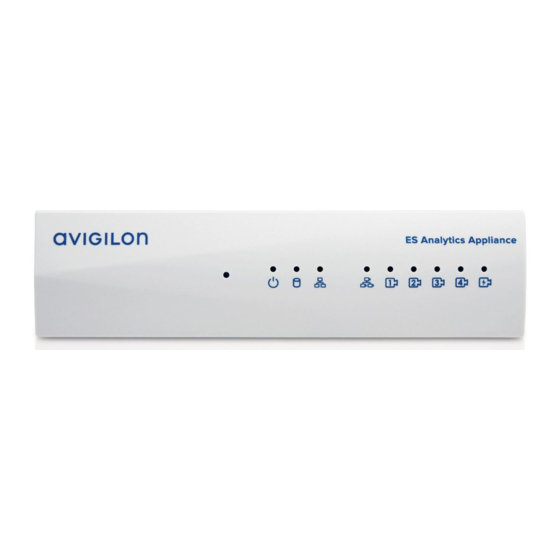
Page 28: Led Indicators
LED Indicators The following list describes what the LEDs on the ACC ES Analytics Appliance indicate. Front Panel LEDs Icons LED Status Description Green Device is powered and running. Orange Device is restarting. Orange - blinking Factory restore button pressed. Green Hard disk drive is connected. -
Page 29: Using The Reset Button
Using the Reset Button The reset button is located at the front of the appliance and is the small unlabeled circle to the left of the System Status LED. For more information, see Front View on page 1 The reset button provides two functions: Restart the system —... -
Page 30: Supported Network Configurations
Supported Network Configurations NOTE: Camera Uplink Port does not support dynamically switching DHCP servers. Supported IP Configurations Camera Web Network Interface Notes Corporate LAN Camera LAN Connections Access Uplink Uplink Camera LAN Uplink and Static or DHCP Unconnected Corporate LAN connected cameras will use Uplink only assigned... -
Page 31: Troubleshooting - Cannot Reach Default Ip Address
ACC Client software: 1. Download and install the ACC Client software on to the configuration laptop. The ACC Client software can be downloaded from the Avigilon website: avigilon.com. 2. Launch the ACC Client software. 3. Log into the site that uses this naming convention: VMA-RPA-4Px-xxxxxxxxxx.AVIGILON. - Page 32 Limited Warranty and Technical Support Avigilon warranty terms for this product are provided at avigilon.com/warranty. Warranty service and technical support can be obtained by contacting Avigilon Technical Support: avigilon.com/contact-us/. Troubleshooting — Cannot Reach Default IP Address...
Need help?
Do you have a question about the VMA-RPA-4P2 and is the answer not in the manual?
Questions and answers