
Related Manuals for Avigilon ENC-4PORT


Summary of Contents for Avigilon ENC-4PORT
-
Page 1: Installation Instructions
Operating and Installation Instructions Avigilon Analog Video Encoder Model ENC-4PORT Avigilon Corporation Vancouver, BC Canada 604.629.5182 604.629.5183 avigilon.com... - Page 2 This page is intentionally left blank.
-
Page 3: Table Of Contents
Contents Important Safety Information Regulatory Notices FCC Notice Disposal and Recycling Information Other Notices Compilation and Publication Notice Intellectual Property Notice Overview Rear View Front View Installation Installation Steps Package Contents Required Tools and Materials Mounting the Encoder Connecting Power Connecting Analog Cameras to the Encoder Connecting the Encoder to a Network Video Recorder (NVR) IP Address Selection... -
Page 4: Important Safety Information
Important Safety Information This manual provides installation and operation information and precautions for the use of this equipment. Incorrect installation could cause an unexpected fault. Before installing this equipment read this manual carefully. Please provide this manual to the owner of the equipment for future use. - Page 5 • Do not use strong or abrasive detergents when cleaning the encoder body. • Use only accessories recommended by Avigilon.
-
Page 6: Regulatory Notices
Changes or modifications made to this equipment not expressly approved by Avigilon Corpo- ration or parties authorized by Avigilon Corporation could void the user’s authority to operate this equipment. Disposal and Recycling Information When this product has reached the end of its useful life, please dispose of it according to your local environmental laws and guidelines. -
Page 7: Other Notices
License and eCos source code are available to the public at http://www.avigilon.com/ ecoslicense. Avigilon reserves all rights to all software not covered under the eCos license. This includes all portions of software that were not distributed to Avigilon as part of the eCos operating system. -
Page 8: Overview
“Connecting the Encoder to a Network Video Recorder” section for more information on the Connection Status LED. It can be turned off during operation for covert installations. See the Avigilon Control Center software documentation for details on how to turn off the encoder’s LEDs. Ethernet Port Provides connection to NVR for communication and image data transmission. -
Page 9: Front View
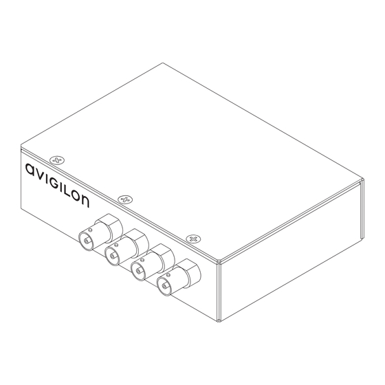
Front View Video Inputs Video Input Status LEDs Feature Description Video Inputs 4 BNC inputs for connecting analog video devices. Video Input Status LEDs Provides information about the status of the analog video signal. The LED turns on when a video signal has been detected. -
Page 10: Installation
Check the package contents against the list below. Mount the encoder. Connect power. Connect cameras to the encoder. Connect the encoder to Avigilon Control Center software. Package Contents The package contains the following: • Avigilon Analog Video Encoder •... -
Page 11: Connecting Power
Warning • If installed in a closed or multi-unit rack assembly, the operating ambient temperature of the rack environment may be greater than room ambient. Ensure that the ambient temperature inside the rack does not exceed the maximum operating temperature of the encoder. •... -
Page 12: Connecting Analog Cameras To The Encoder
Important: To avoid networking problems, use only network switches recommended by Avigilon. Connect the encoder to the same network as the NVR running the Avigilon Control Center software. The encoder will automatically obtain an IP address and will be detected by the software. -
Page 13: Ip Address Selection
When the encoder’s IP address is set using Zeroconf, its IP address is in the 169.254.* subnet. The encoder can be set to a static IP address from the Avigilon Control Center software. Consult the software user guide for details. -
Page 14: Advanced Features
Advanced Features Upgrading the Firmware The encoder’s firmware can be field-upgraded via the Avigilon Control Center software. Consult the software user guide for details on how to perform a firmware upgrade. It is possible for the encoder’s firmware to become corrupted during an upgrade (for instance, if power is lost during the upgrade process). -
Page 15: Connecting To External Devices
Connecting to External Devices The encoder can be connected to external devices through the I/O terminal on the rear of the encoder. The pinout for the I/O terminal is shown in the table below. Consult the software user guide for details on how configure the I/O. Table: External I/O Terminals Pin Function Description... - Page 16 The encoder schematic and example applications are show in the figure below. 9-12 Relay Switch External Device RS-485 (e.g. Tan/Tilt) Encoder Figure: External I/O Terminal Schematics and Example Applications...
-
Page 17: Specifications
Specifications Network Network 100BASE-TX Cabling Type CAT5 Connector RJ-45 Security Protocol UDP, TCP, SOAP, DHCP, Zeroconf Mechanical Dimensions (LxWxH) 140 mm x 122 mm x 44 mm 5.5” x 4.8” x 1.7” Weight 0.62 kg (1.4 lbs) Electrical Power Source VDC: 12-24 V VAC: 24 V PoE: IEEE802.3af Class 3 compliant... -
Page 18: Limited Warranty & Technical Support
Limited Warranty & Technical Support Avigilon warrants to the original consumer purchaser, that this product will be free of defects in material and workmanship for a period of 3 years from date of purchase. The manufacturer’s liability hereunder is limited to replacement of the product, repair of the product or replacement of the product with repaired product at the discretion of the manufacturer. -
Page 19: Notes
Notes... - Page 23 This page is intentionally left blank.
- Page 24 ©2009 Avigilon Corporation V1.2...
Need help?
Do you have a question about the ENC-4PORT and is the answer not in the manual?
Questions and answers