Table of Contents
Advertisement
Quick Links
Advertisement
Table of Contents

Related Manuals for Chen Hsong Ai-02

Summary of Contents for Chen Hsong Ai-02
- Page 1 Ai-02 Operation Manual Chen Hsong Ai-02 Injection Multi-function Computer Operation Manual CHENHSONG HOLDINGS LTD. TEL : +852-26653888,26653222 (Headquaters, Hong Kong) +86-755-84139999 (Industrial park, Shenzhen) Web : www.chenhsong.com.hk Version: 2013_04...
-
Page 2: Table Of Contents
Ai-02 Operation Manual Contents 1.Characteristics:........................5 2.Basic features.........................5 3.Function Comparison ......................6 4. Introduction on each Part of Computer’s Panel..............7 4.1 Computer’s Panel ......................7 4.2 Keys for Operation Mode control..............8 4.3 Keys for function of forming conditions............8 4.4 Digital data key, cursor key and auxiliary operational .........9 4.5Power Switch:...................10... - Page 3 6.4.1 Ai-02 Input Connection (Encoder Version)..........110 6.4.2 Ai-02 I/O Board Layout (potentiometer version)...........111 6.4.3 Ai-02 Motor & Power Control Circuit Diagram(piston pump)....112 6.4.4 Ai-02 Motor & Power Control Circuit (SVP)..........113 ..........................114 6.4.5 Ai-02 Input Point Connection Diagram of Computer I/O Board (potentiometer)......................114...
- Page 4 Ai-02 Operation Manual 6.4.6 Ai-02 Input Point Connection Diagram of Computer I/O Board ....115 6.4.7 Ai-02 Output Point Connection Diagram of Computer I/O Board....116 6.4.8 Ai-02 extension I/O board Connection Diagram...........117 6.4.9 Ai-02 Robot Interface (Euromap 67).............118...
-
Page 5: Characteristics
Ai-02 Operation Manual 1.Characteristics: It is designed, researched and developed by using the technology of Japan and complying with JIS standards, equipped with TFT 320×240 color liquid crystal display. Power range applies to AC110V ~ AC280V 50/60HZ. It features LED backlight, high brightness and long life of usage. -
Page 6: Function Comparison
27. Perfect support for iChen System of workshop network management. 28. Perfect support for iChen Wireless Network. 3.Function Comparison Ai-02 Multi-function computer is the upgraded version of Ai-01 computer. The detailed comparison in function are as follows: FUNCTION AI-02... -
Page 7: Introduction On Each Part Of Computer's Panel
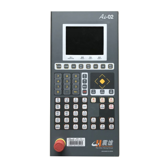
Ai-02 Operation Manual 4. Introduction on each Part of Computer’s Panel 4.1 Computer’s Panel... -
Page 8: Keys For Operation Mode Control
Ai-02 Operation Manual 4.2 Keys for Operation Mode control 4.3 Keys for function of forming conditions The keyboard is responsible for the switch of forming operation status. The keyboard has the following functions: (1)Can set the forming conditions like position, speed, pressure, time, counter and temperature, etc. -
Page 9: Digital Data Key, Cursor Key And Auxiliary Operational
Ai-02 Operation Manual 4.4 Digital data key, cursor key and auxiliary operational This keyboard has the following functions: If press at the same time, then turn on the power of the computer, the mould data and system setting inside the computer can be initialized. -
Page 10: Power Switch
Ai-02 Operation Manual 4.5Power Switch: (1)Emergency Stop Button The Emergency Stop Button locates in the bottom-right of the computer operation panel. If press it, the power can be cut off. If restart is required, the button must be released by turning rightward. - Page 11 Ai-02 Operation Manual (1)After the computer is powered on and when the system is performing automatic test, at which moment the startup screen (00) is displayed, just input the account no. and password you will be authorized to log into the control system if the...
-
Page 12: Setting Normal Operation
Ai-02 Operation Manual Setting normal operation Interface of normal operation (03) is as follows under normal operation: Interface of normal operation (03) (1)Press one time to display this interface (After the normal start of the system, the default is manual operation. After the start is completed, this interface will appear automatically). -
Page 13: Monitor The Cycle
Ai-02 Operation Manual "T2": Stage 2 temperature setting "T3": Stage 3 temperature setting "T4": (depend on machine model) Stage 4 temperature setting "T5": (depend on machine model) Stage 5 temperature setting "T6": (depend on machine model) Stage 6 temperature setting "T7":... -
Page 14: Setting Of Mould Opening
Ai-02 Operation Manual Setting of Mould opening Interface of Setting of Mould opening (05) (1)Press to call mould open close setting screen . (2)Use to select the parameters to be set, input the numerical value and press , then the setting is completed. -
Page 15: Setting Of Mould Closing
Ai-02 Operation Manual “JJ”: Setting for speed of fast mold opening “KK”: Setting for pressure of fast mold opening “LL”: Setting for ending position of fast mold opening “MM”: Setting for speed of slowed mold opening “NN”: Setting for pressure of slowed mold opening “OO”: Setting for ending position of slowed mold opening... - Page 16 Ai-02 Operation Manual (2) press key to select the clamping parameters。 Input proper value ,and then press key,to complete the setting。 clamping force” is use to display the clamping force and correspond pulse position for automatic force adjustment. CLP POS:“25999p”mean the current position of clamping。...
-
Page 17: Interface Of Mould Clamping And Injection Pressure Setting
Ai-02 Operation Manual 5.6 Interface of Mould Clamping and Injection Pressure Setting Interface of Mould Clamping and Injection Pressure Setting (07) (1) Press for three times or for five times and you can enter into interface of mould clamping and injection pressure setting (07). - Page 18 Ai-02 Operation Manual Press and you can enter into interface of injection setting (08). Use to select the parameters of injection to be set, Input the numerical value and press the, then the set is completed. Of which, "AA": Set the filling time from stage 1 – 5 of injection "BB":...
- Page 19 Ai-02 Operation Manual "OO": Set the termination of action of stage 4 of injection "PP": Set the speed of stage 5 of injection "QQ": Set the pressure of stage 5 of injection "RR": Set the termination of action of stage 5 of injection...
-
Page 20: Setting Of Pressure Holding
Ai-02 Operation Manual Setting of pressure holding Interface of setting of pressure holding (09) Press for two times and you can enter into interface of pressure holding (09). Use to select the parameters to be set, Input the numerical value and press the, then the set is completed. - Page 21 Ai-02 Operation Manual “GG”: Setting for pressure of 2 nd stage of pressure holding “HH”: Setting for time of 2 nd stage of pressure holding “II”: Setting for speed of 3 rd stage of pressure holding “JJ”: Setting for pressure of 3 stage of pressure holding “KK”: Setting for time of 3...
-
Page 22: Setting Of Plasticizing/Back Pressure
Ai-02 Operation Manual Setting of plasticizing/back pressure Interface of plasticizing/back pressure setting (10) Press for three times and you can enter into interface of plasticizing/backlash setting (10). Use to select the parameters of plasticizing to be set, Input the numerical value and press the, then the set is completed. - Page 23 Ai-02 Operation Manual "HH": Set the termination of action of stage 1 of plasticizing "II": Set the speed of stage 2 of plasticizing "JJ": Set the pressure of stage 2 of plasticizing "KK": Set the back press of stage 2 of plasticizing "LL":...
-
Page 24: Setting Of Automatic Purge
Ai-02 Operation Manual 5.10 Setting of automatic purge Interface of automatic purge (11) Press for four times and you can enter into interface of (1) automatic purge (11). Use to select the parameters of automatic plastic purge to (2) be set,... -
Page 25: Setting Of Ejector
Ai-02 Operation Manual Function of automatic purge is used when resin is changed. Purge time is the number of purging cycle 5.11 Setting of Ejector Interface of Ejector Setting (12) ( 1 ) Press and you can enter into interface of Ejector setting (12). - Page 26 Ai-02 Operation Manual (i) unused (ii) Ejector pause (iii) several Ejectors "FF": Set the speed of ejection forward 1 "GG": Set the pressure of ejection forward 1 "HH": Set the termination of action of ejection forward 1 "II": Set the speed of ejection forward 2 "JJ":...
-
Page 27: Setting Of Carriage
Ai-02 Operation Manual 5.12 Setting of Carriage Interface of Setting of Carriage (13) Press for two times and you can enter into Interface of Setting of Carriage (13). Useto select the parameters of Carriage to be set, Input the numerical value and press the, then the set is completed. -
Page 28: Setting Of Air Blowing
Ai-02 Operation Manual 5.13 Setting of air blowing Interface of Blowing Setting (14) Press for three times and you can enter into interface of (1) Blowing Setting (14). (2) Useto select the parameters of blowing to be set, Input the numerical value and press the, then the set is completed. -
Page 29: Setting Of Core Pulling A
Ai-02 Operation Manual 5.14 Setting of Core pulling A Setting Interface of Core Pulling A (15) (1) Press for four times and then the interface of setting core pulling A (15) will appear. Useto select the parameters of core pulling to be set,... - Page 30 Ai-02 Operation Manual (4) Unused "BB": Pulling core: useto select from the following four modes (1) Before mould opening (2) After mould opening (3) Mould opening midway (set clamping position of pulling core starting) (4) Unused "CC": Cycle of inserting/pulling core: use to...
-
Page 31: Setting Of Core Pulling B
Ai-02 Operation Manual 5.15 Setting of Core pulling B Setting Interface of Core Pulling B (16) Press for five times and then the interface of setting core pulling B (16) will appear. (2) Useto select the parameters of core pulling to be set,... - Page 32 Ai-02 Operation Manual "BB": Pulling core: useto select from the following four modes Before mould opening After mould opening Mould opening midway (set clamping position of pulling core starting) Unused "CC": Cycle of inserting/pulling core: use to select from the following two modes...
-
Page 33: Setting Of Core Pulling C
5.16 Setting of Core pulling C Setting Interface of Core Pulling C (17) Press for six times and then the interface of setting core pulling C (17) will appear. (2) Use to select the parameters of core pulling to be set, Input the numerical value and press the , then the set is completed. - Page 34 "BB": Pulling core: useto select from the following four modes (1) Before mould opening (2) After mould opening Mould opening midway (set clamping position of pulling core starting) (4) Unused "CC": Cycle of inserting/pulling core: uset select from the following three modes (1) Time (2) Position switch (3) Count...
-
Page 35: Setting Of Timer
5.17 Setting of Timer Interface of Time Setting (18) Press and then the interface of time setting (18) will appear. Use to select the time to be set, Input the numerical value and press the , then the set is completed. - Page 36 "GG": Set the time of monitoring of low pressure clamping "HH": Set the time of quick carriage forward "II": Set the time delay of carriage forward termination "JJ": Set the time delay of injection "KK": Set the time of retraction of Ejector shake "LL":...
-
Page 37: Setting Of Counter 1
5.18 Setting of Counter 1 Interface of Counter Setting (19) Press for two times, and then the interface of counter setting (19) will appear. Use to select the counter to be set, Input the numerical value and press the , then the set is completed. - Page 38 "DD": Standby "EE": Cycle monitor "FF": Set mould clamping by the adjustment "GG": Set mould pressing by the calibrating "HH": Standby "II": C timers of inserting cores "JJ": C timers of pulling cores...
-
Page 39: Setting Of Temperature Deviation Alarm
5.19 Setting of Temperature Deviation Alarm Interface of Setting of Temperature Deviation Alarm (20) (1) Press ,then the interface of temperature alarm (20) will appear. (2)Use to select the deviation alarm of each stage of temperature to be set, input the numerical value and press the, then the set is completed. -
Page 40: Temperature Setting Of Hot Runner
5.20 Temperature setting of hot runner Interface of Temperature setting of hot runner (21) Interface of Temperature setting of heat interval channel (22) - Page 41 ( 1 ) Press for two times, then the interface of temperature setting of heat interval channel (21) will appear. 、 Press for three times, then the interface of temperature setting of heat interval channel (22) will appear. Use to select temperature of each stage of heat interval channel to be set, input the preset alarm numerical value and press then the set is completed.
-
Page 42: Setting Of Function
5.21 Setting of Function Interface of Setting of Function (23) Press then the interface of setting of function (23) will appear. Use to locate the cursor in the function settings, press and select “ON”; press and select “OFF”, then the set is completed. (3) Automatic stop selection: use to select the following four modes, which are used with forming numbers,... - Page 43 (i) Not used (ii) oil pump (iii) electric heat (iv) oil pump and electric heat (4) Switching between filling and pressure holding by pressure holding function: Switching by time: in selecting time switching, timer TIM014 counting is completed and pressure holding is switched.
-
Page 44: The Selection Of Mould Data
5.22 The Selection of Mould Data The interface of Selection of Mould Data (24) The interface of Selection of Mould Data (25) - Page 45 LED light off。 Backup of mold data in FRAM: FRAM is a new memory device on the CPU board of Ai-02 controller, it can be used for backup of mold data and machine parameters when the battery is in failure。...
-
Page 46: Statistical Value
the Mold set data number 1 to 10 saved in the FRAM. 5.23 Statistical value Quality statistics interface (26) Press key for three times, and it will show the quality statistics interface (26). - Page 47 (2) Select the setting item by the key, input the figure and then press key to complete the setting. This screen is for monitoring of quality data. If it is setting with "ON", it is judge to be defective product if data are out of tolerance. key to move the setting of“production time”...
-
Page 48: Time Monitor
5.24 Time monitor Time monitor interface (27) Time monitor interface (28) Time monitor interface (29) - Page 49 Time monitor interface(30)
- Page 50 Time monitor interface (31) Press thekey once, and it will show Time monitor interface (27). In the interface, the setting and operation status of timer can be monitored, in case of monitoring other timers, press simultaneity press keys, switch between interface(27)-(31).
-
Page 51: Counter Monitor
5.25 Counter monitor Counter monitor interface (32) Press key for twice, it will show counter monitor interface (32). The interface is mainly used for monitoring setting and working status of counters. 。 This screen is to monitor counter data... -
Page 52: Input Monitor
5.26 Input monitor Input monitor interface (33) Press key for three times, it will show input monitor (1) interface(33). In the screen, the input status can be monitored, in case of (2) monitoring others screen, press to switch between the interfaces(33)- (34)... -
Page 53: Output Monitor
5.27 Output monitor Output monitor interface (34) Press four times to call the output monitor screen. In this interface, the setting and operation status of outputs can be monitored, in case of monitoring other outputs status, simultaneously press )keys to switch among the page . - Page 54 5.28 Relay monitor Relay monitor (35) Press five times to call the relay monitor screen. In this interface, internal relays status can be monitored, in case of monitoring other relays status, press ) keys to switch among relay monitor interfaces. These interfaces are used to confirm whether the signal receiving and sending function of controller internal relays is in normal condition, in case of failure during the machine operating, troubleshooting can be found through these interfaces( in...
-
Page 55: Program Monitor
5.29 Program monitor Program monitor interface (36) Press six times, it will show program monitor screen. "EI": Input position of internal relay types, press key to switch internal relay types, then press key to confirm. "0": Input position of internal relay serial number, input the serial number, and then press key to confirm. -
Page 56: Injection Termination Position
5.30 Injection termination position Injection termination position interface (37) Press key for one time, it will show injection termination interface (44).The interface can show the injection termination position and the average of 50 mould products produced. -
Page 57: Injection Speed Curve
5.31 Injection speed curve Injection speed curve interface (38) Press twice to call the injection speed curve screen. Press ,move the cursor position,press key to save the previous curve as standard curve for comparsion。 Move cursor to position,press key to select the display of standard curve,if it is“ON”, the standard curve will be display and compared with every new injection curve in e each cycle. -
Page 58: Injection Pressure Curve
5.32 Injection pressure curve Injection pressure curve interface (39) Press three times to call the injection pressure curve screen. key,to move the cursor to position,press key to save the current injection pressure curve as standard curve for comparsion in the next cycle. Move the cursor to position,press key to select... -
Page 59: Help
5.33 Help Help interface (40) Help interface (41) Help interface (42) - Page 60 Help interface (43) (1) Press key for one time, it will show help interface (47). to select help types. (2)Press Help types include Function Introduction, Data Introduction, Alarm and Maintenance.
-
Page 61: Language And System Time Setting
Press key, move the cursor from the main catalogue to the sub- catalogue, then press key, to check the detailed description of help content. 5.34 Language and System time setting Language and System time setting interface (44) Press at the same time to enter into language (1)... -
Page 62: Action Stroke Stage Numbers Selection
5.35 Action stroke stage numbers selection Stage numbers selection (45) Press ,input supervisor password,setting necessary + number of stages need for processing. In which: "A1"~"A5" are respective the stage numbers setting value of mould opening, mould clamping, injection, pressure holding and plasticizing. Data setting locking function Press key,move cursor to... -
Page 63: Ramp Setting
Data keys To release the locking of data key , press , screen comes + out as shown below , inputing the keylock password , then press key “ , ON”will be changed to“OFF” it mean it is unlocked. If the keylock password was forgot, it is necessary to input the supervisor password;or set to“0”,the press 5.36 Ramp setting... -
Page 64: Speed 1 Output Setting
keys, and enter slope setting interface(54). (1)Press Press key, to choose slope, and input corresponding slope, then key, to complete setting. (2)press Of which, "S" :the abbreviation of Speed "PR":the abbreviation of Press "BP":the abbreviation of Back Press S11:Speed slope of fast mould clamping and low pressure mould clamping S12:Speed slope of mould opening;... -
Page 65: Pressure Output
Press keys twice, and it will show speed 1 setting (1) output interface (47). Press key, to choose speed, and input corresponding speed, (2) then press key, to complete setting. (3) Of which, "AA":Speed percentage "BB":Analog value of speed output Note: As the speed percentage increasing, the corresponding analog value of speed output will also increase, decreasing is not allowed, otherwise, the output speed signal will be in disturbance, which causes the machine instable. - Page 66 Pressure output setting interface (48) Press keys for three times, and it will show pressure (1) output setting interface(48). Press key, to choose pressure, and input the (2) corresponding pressure, then press key, to (3) complete setting. Of which, "AA":Pressure percentage "BB":Analog value of pressure output Note: As the pressure percentage increasing, the corresponding analog value of pressure output will also increase, decreasing is not allowed, otherwise, the...
-
Page 67: Back Pressure Output Setting
5.39 Back pressure output setting Page layout of back press output setting (49) Press key for 4 times, and it comes the page layout of (1) back press output setting(49). Press key to select back press, input the (2) corresponding back press figure, and then press (3)... -
Page 68: Speed 2 Output Setting
(The analog voltage output range is 0~10V,current range is 0~0.8A). 5.40 Speed 2 output setting Speed 2 output setting (50) Press key for 5 times, and it comes the page layout of + (1) the velocity 2 output setting(50). Press key to select velocity, input the (2)... -
Page 69: Initial Setting (Origin Setting For Decoder)
corresponding velocity, and then press key to (3) complete the setting. Of which, "AA":Velocity percentage "BB":Analog value of velocity output Note: As the speed percentage increasing, the corresponding analog value of speed output will also increase, decreasing is not allowed, otherwise, the output speed signal will be in disturbance, which causes the machine instable. - Page 70 By pressing key, select item to be input, input corresponding (2) value, and press key to complete setting. (3) Of which, "AA":Set mould thickness "BB":Minimum of mould clamping position "CC":Maximum of mould clamping position "DD":Preset of mould clamping position "EE":Preset of ejector position "FF":Preset of injection position "GG":Original value of mould clamping "HH":Original value of ejector...
-
Page 71: Auxiliary Velocity And Pressure Setting
5.42 Auxiliary velocity and pressure setting Page layout for auxiliary velocity and pressure setting (52) Page layout for auxiliary velocity and pressure setting(53) Press key for seven times at the same time, display + (1) the Page layout for standby velocity and pressure setting(60), and further page down to indicate the page layout for standby velocity and pressure setting(61). -
Page 72: Timer Setting
Clamping force"A6" : clamping speed during automatic clamping force adjustment; Clamping force"B6" : clamping pressure during automatic clamping force adjustment; High clamping pressure"B7":High clamping pressure setting; Open Aux 2"A7":setting auxiliary open position ,sometimes use for position to start the back pressure control of opening。 OT012: is the pressure and speed for origin setting;... - Page 73 press key to complete setting. (3) Of which, "AA":Motor Y→ start time △ "BB":Time resetting for decoder origin "CC":Time setting for mould calibrating monitoring "DD":Siren lasting time setting "EE":Siren stop time setting "FF":Action monitoring time setting "GG":Standby "HH":Standby "II": Ejection and retraction interval setting "JJ":...
-
Page 74: Counter Setting 2
5.44 Counter setting 2 Page layout for counter setting (55) key for 9 times, and it comes the page layout for (1)Press + counter setting(55). Press to select the item to be set, input the corresponding value, and press to complete the setting. -
Page 75: Factory Setting
5.45 Factory setting Page layout for factory setting (56) Page layout for factory setting (57) (1) Press key for 10 times, it comes the page + layout for factory setting (56), and further page down to indicate the page (57). - Page 76 (2) Press key to select item to be input, input corresponding value, and press key to complete setting. Of which, "AA":Machine model setting "BB":Machine number setting "CC":Setting of date of production "DD":Max injecting speed setting "EE":Start delay setting "FF": Regulating delay setting for each closed Loop "GG":Time interval setting for closed Loop regulating Factory setting screen 1 is for machine information.
-
Page 77: Warning Record Display
5.46 Warning record display Page layout of warning record display (58) Press at the same time to display the page layout of (1) warning record display (58). Press key to check the contents of the warning records. (2)... -
Page 78: Network
(which is available when you have bought the iCHEN network system of CHEN HSONG Corp. ). (2) Then, press key to switch to the item to be set.、... - Page 79 "AA": Press key to select following 13 modes (1) Machine regulating (2) Stop (3) Malfunction (4) Waiting for mould (5) Waiting for material (6) Material changing (7) Mould changing (8) Mould testing (9) Mould modifying (10) Color blending (11) Production (12) No order (13) Others 3 "...
-
Page 80: Password Modification
5.48 Password modification Page layout of password modification (60) Press key for over three seconds ,to call the change password + screen (This password is used system operator and supervisor). Press to select the item to be set, input the corresponding value, and press key to complete the setting. -
Page 81: Manual Lubrication Setting
5.49 Manual lubrication setting Page layout for manual lubrication setting (61) Press to call the manual lubrication setting screen . Press key to select the parameters to be set, input the value and press to complete the setting. In this screen: "A1"... -
Page 82: Mould Adjustment Setting
5.50 Mould Adjustment setting Page layout for mould adjustment setting (62) Press to call the mould adjustment setting screen . Press key to select the parameters to be set, input the value and press to complete the setting. is for hydraulic mold adjustment,press select ON and OFF mode。This should be OFF when electric motor is used for mold adjustment。Hydraulic mold adjustmen consist of speed and pressure setting data 。... - Page 83 clamping force adjustment. By turning ON this function ,automatic clamping force adjustment wil be done after mold thickness adjustment was completed 。 is the position where the clamping force can be achieved by automatic clamping force adjustment , is the point for switching high pressure clamping。...
-
Page 84: Machinery Adjustmment
5.51 Machinery Adjustmment Page layout for machinery adjustment(63) Press to call the machine adjustment screen . Press key to switch to A, input the value and press to complete the setting. This screen is mainly used for machine adjustment, all current actions speed of the machine will reduce the set percentage. -
Page 85: Maintenance Setting
5.52 Maintenance setting Page layout for maintenance setting (64) Press 14 times to call the maintenance setting screen . + Press to move the cursor to “Last Date” position, and press key, a “?” appears after the “Last Date”, then press key to confirm and initialize the “Last Date”... -
Page 86: Reset Method Of Initial Point
5.53 Reset method of initial point In the event of machine is in operation, the computer is suddenly cut off. The screen prompts warning signal to remind operator to reset initial point while restarting the computer. Check the following setting values prior to initial point reset: Setting of initial point speed and pressure Speed = 50% Pressure = 99%... -
Page 87: Initial Position Setting Of Decoder
Press button, and the ejector retraction is back to the end after 4 退 针 E J E C T B W D seconds running of Timer TIM20 with warning signal disappearing. The actual position of ejector is automatically changed to preset position with setting value of 0.5mm, and the initial point reset is completed. - Page 88 Presetting — manually adjust initial point position While the machine is operating, if the initial point changes, the right initial point position can be relocated by manually adjusting initial point. (3) Manually adjust initial point position of mould clamping method Before manually adjust initial point, please check the following setting values: Initial...
- Page 89 (4) Manually adjust injection initial point position method Note: Plasticizing cylinder temperature must reach the setting temperature. Injection presetting position: GG = 0.5mm. Press key, injection touched the bottom, and the actual injection position is I N J 射 胶 automatically changed to preset position with setting value of 0.5mm, and the manual injection initial point setting is completed.
- Page 90 Note: Plasticizing cylinder temperature must reach setting temperature. In the initialization setting interface(61),and in the injection initial point position IIp, input a larger value( e.g.100mm).This value must be less than the plasticizing position setting value. (ii) Manual status, it is required for injection and plasticizing for three times respectively.
-
Page 91: Alarm And Treatment
avoid affecting the stability of machine. 6. Alarm and Treatment Title Explanation of Computer Alarm Title Explanation AL000 Alarm 1 Failure to use AL001 Alarm 2 Failure to use AL002 Temperature of the feeding pipe Actual temperature of the feeding pipe is lower than the does not meet the setting value summation of temperature’s setting value and low temperature deviation... - Page 92 Title Explanation Forming moulding number has reached the due Has reached the settting forming AL024 production setting moulding number. It is under the moulding number condition of hand movement. Cycle production time is beyond the due cycle alarm Excessive cycle time AL025 time.
- Page 93 force Title Explanation Actual temperature of the feeding Actual temperature of the feeding pipe is beyond the AL043 pipe is setting value(+high temperature deviation) Safety door limit breakdown Safety door limit switch has no signal within the setting AL045 time Termination breakdown of Mould Mould opening time is beyond the setting time in AL046...
- Page 94 In reserve Failure to use AL077 In reserve Failure to use AL078 In reserve Failure to use AL079 In reserve Failure to use AL080 In reserve Failure to use AL081 In reserve Failure to use AL082 In reserve Failure to use AL083 Ejector does not backspace Does not detect the backspacing signal of the...
-
Page 95: Explanation Of Forming Operation
Explanation of Forming Operation 6.2.1 Temperature Control Setting When starting the power, display the temperature, and refer to the page (03). Sign “◢” appearing on the operating panel shows electro thermal chip is heating, and temperature control button will light. (1) Temperature Setting of Each Stage: While setting the temperature of first stage, press the button , and set the temperature on the screen T1, produce the inverted cursor, and then... -
Page 96: Temperature Deviation (Alarm) Setting
Heat preservation stage of the nozzle is a stage to control constant temperature. The stage could be applied in the nozzle of the feeding pipe where needs the constant temperature control and its setting value is 00%-99%. When setting as 99%, constant temperature inside the computer could be set as 10-30 seconds all time heating, if setting as 20 seconds heating, i.e. -
Page 97: Heat Preservation Setting
6.2.3 Heat Preservation Setting: For setting the heat preservation function, refer to the page (20). Heat preservation means to keep the setting temperature of each stage in the set percentage of the heat preservation. For example: Set 20%, and the setting temperature is 250℃ 250℃... -
Page 98: Adjustment Of Proportional Control
(2) For the positing material setting, there are two methods such as optical decoder parameter (P) and distance setting value (mm). When setting the distance, the computer could automatically switch the value of optical decoder. (3) When stopping in the page of needing action and the operator does not have to revise or set the material, press the button or orany one of there M A N 手... - Page 99 For the details, please carry on the linear adjustment of the pressure and speed according the methods in page (45) and (46). Only finishing the linear adjustment, the computer could continue the next operation. (2) Open Loop Controlling Generally, all belongs to the way of open loop controlling. At this moment, proportional digital controlling can only be adjusted through hand movement.
-
Page 100: Instruction Of The Counter Inside The Computer
6.2.8 Instruction of the Counter inside the Computer Function Explanation CT000 Cycle count Setting of forming moulding number CT001 Non-qualified moulding Setting of non-qualified moulding number number CT002 Production time counter Total time needed in production, per 0.1 hour CT003 In reserve CT004 Variation times of the Setting of the variation times of the ejector... -
Page 101: Instructions For Usage Of Timer Inside The Computer
6.2.9 Instructions for usage of timer inside the computer Function Description TM000 Used by system Time indication of cycle TM001 Used by system Time indication of clamping TM002 Used by system Time indication of carriage advance TM003 Used by system Time indication of filling TM004 Used by system... - Page 102 TM028 Time of core inserting D Reserved Function Description TM029 Time of core pulling D Reserved TM030 Lubrication time Output time of lubricant, which is suggested to set over 10 seconds TM031 Lubrication alarm time Reserved TM032 Carriage advance Duration of rapid stage of carriage advance rapidly TM033 Time of carriage During the half/full automatic operation, time of...
- Page 103 Function Description TM056 Reserved Reserved TM057 Reserved Reserved TM058 Reserved Reserved TM059 Reserved Reserved TM060 Start of electric machine Motor start Y→△time TM061 Origin resetting Origin resetting time of decoder, which is suggested to set 3~5 seconds. TM062 Mould adjustment Mould adjustment sensor monitor time.
- Page 104 TM076 Back pressure of Duration of synchronous opening and back opening pressure TM077 Open the nozzle Action time of opening the nozzle (used by the function of closing the nozzle by oil pressure) TM078 Injection buffer Buffer time of injection TM079 Plasticizing buffer Buffer time of plasticizing...
-
Page 105: Description For Input & Output Point Of Computer
6.2.10 Description for input & output point of computer Function Description Input point Front safe door Input point Rear safe door Input point Safe threshold Input point Front limit of nozzle Input point B limit of inserting core Input point B limit of pulling core Input point Reserved... - Page 106 Function Description Input point Termination of closing door Clamping resetting Input point Input point Ejector resetting Input point Injunction resetting...
- Page 107 Function Description Output point Advance of mould adjustment Output point Retraction of mould adjustment Output point Advance of clamping Output point Advance of carriage Output point Injection Output point Plasticizing Output point Backlash Output point Retraction of carriage Output point Opening Output point Advance of ejector...
- Page 108 Function Description Output point Full automation Output point Opening termination Output point Safe door closing Output point Core inserting C Output point Core pulling C...
-
Page 109: Ai-02 Special Interface Operation
Ai-02 Special Interface Operation 1 Automatic Purge Setting Interface(10) Press injection key for four times 2 Carriage Setting Interface(12) Press Ejector/core pulling key for two times 3 Temperature Alarming Interface(19) Press electric heat key for one time 4 Heat Interval Channel Temperature... -
Page 110: Ai-02 Circuit Diagram
6.4 Ai-02 circuit diagram 6.4.1 Ai-02 Input Connection (Encoder Version) -
Page 111: Ai-02 I/O Board Layout (Potentiometer Version)
6.4.2 Ai-02 I/O Board Layout (potentiometer version) -
Page 112: Ai-02 Motor & Power Control Circuit Diagram(Piston Pump)
6.4.3 Ai-02 Motor & Power Control Circuit Diagram(piston pump) -
Page 113: Ai-02 Motor & Power Control Circuit (Svp)
6.4.4 Ai-02 Motor & Power Control Circuit (SVP) -
Page 114: Ai-02 Input Point Connection Diagram Of Computer I/O Board (Potentiometer)
6.4.5 Ai-02 Input Point Connection Diagram of Computer I/O Board (potentiometer) -
Page 115: Ai-02 Input Point Connection Diagram Of Computer I/O Board
6.4.6 Ai-02 Input Point Connection Diagram of Computer I/O Board... -
Page 116: Ai-02 Output Point Connection Diagram Of Computer I/O Board
6.4.7 Ai-02 Output Point Connection Diagram of Computer I/O Board... -
Page 117: Ai-02 Extension I/O Board Connection Diagram
6.4.8 Ai-02 extension I/O board Connection Diagram... -
Page 118: Ai-02 Robot Interface (Euromap 67)
6.4.9 Ai-02 Robot Interface (Euromap 67)
Need help?
Do you have a question about the Ai-02 and is the answer not in the manual?
Questions and answers