Table of Contents
Advertisement
Quick Links
Advertisement
Table of Contents

Related Manuals for thomann STAIRVILLE Outdoor Stage PAR 12 X 3W Tri


Summary of Contents for thomann STAIRVILLE Outdoor Stage PAR 12 X 3W Tri
- Page 1 Outdoor Stage PAR 12 × 3W Tri LED PAR user manual...
- Page 2 Musikhaus Thomann Thomann GmbH Hans-Thomann-Straße 1 96138 Burgebrach Germany Telephone: +49 (0) 9546 9223-0 E-mail: info@thomann.de Internet: www.thomann.de 26.10.2018, ID: 256293 (V5)
-
Page 3: Table Of Contents
Table of contents Table of contents General notes............................... 5 1.1 Further information........................... 6 1.2 Notational conventions........................7 1.3 Symbols and signal words....................... 8 Safety................................10 Features............................... 15 Installation..............................17 Starting up..............................22 Connections and operating elements................... 25 Operating..............................28 7.1 Starting the device........................... 28 7.2 Main menu............................ - Page 4 Table of contents 7.6 Functions in 8-channel DMX mode................... 38 Technical specifications........................44 Plug and connection assignments....................45 Troubleshooting............................46 Cleaning............................... 48 Protecting the environment......................49 LED PAR...
-
Page 5: General Notes
General notes General notes This manual contains important instructions for the safe operation of the unit. Read and follow the safety instructions and all other instructions. Keep the manual for future reference. Make sure that it is available to all those using the device. If you sell the unit please make sure that the buyer also receives this manual. -
Page 6: Further Information
General notes 1.1 Further information On our website (www.thomann.de) you will find lots of further information and details on the following points: Download This manual is also available as PDF file for you to download. Use the search function in the electronic version to find the topics of Keyword search interest for you quickly. -
Page 7: Notational Conventions
General notes 1.2 Notational conventions This manual uses the following notational conventions: Letterings The letterings for connectors and controls are marked by square brackets and italics. Examples: [VOLUME] control, [Mono] button. Displays Texts and values displayed on the device are marked by quotation marks and italics. Examples: ‘24ch’... -
Page 8: Symbols And Signal Words
General notes 1.3 Symbols and signal words In this section you will find an overview of the meaning of symbols and signal words that are used in this manual. Signal word Meaning DANGER! This combination of symbol and signal word indicates an immediate dangerous situation that will result in death or serious injury if it is not avoided. - Page 9 General notes Warning signs Type of danger Warning – high-voltage. Warning – hot surface. Warning – dangerous optical radiation. Warning – suspended load. Warning – danger zone. Outdoor Stage PAR 12 × 3W Tri...
-
Page 10: Safety
Safety Safety Intended use This device is intended for use as an electronic lighting effect by means of LED technology. The device is designed for professional use and is not suitable for use in households. Use the device only as described in this user manual. Any other use or use under other operating con‐ ditions is considered to be improper and may result in personal injury or property damage. - Page 11 Safety Safety DANGER! Danger for children Ensure that plastic bags, packaging, etc. are disposed of properly and are not within reach of babies and young children. Choking hazard! Ensure that children do not detach any small parts (e.g. knobs or the like) from the unit.
- Page 12 Safety DANGER! Electric shock caused by high voltages inside Within the device there are areas where high voltages may be present. Never remove any covers. There are no user-serviceable parts inside. Do not use the device if covers, protectors or optical components are missing or damaged.
- Page 13 Safety WARNING! Risk of epileptic shock Strobe lighting can trigger seizures in photosensitive epilepsy. Sensitive persons should avoid looking at strobe lights. WARNING! Risk of burns The surface of the device can become very hot during operation. Do not touch the device with bare hands during operation, and after switching off wait for at least 15 minutes.
- Page 14 Safety NOTICE! Power supply Before connecting the device, ensure that the input voltage (AC outlet) matches the voltage rating of the device and that the AC outlet is protected by a residual current circuit breaker. Failure to do so could result in damage to the device and possibly injure the user.
-
Page 15: Features
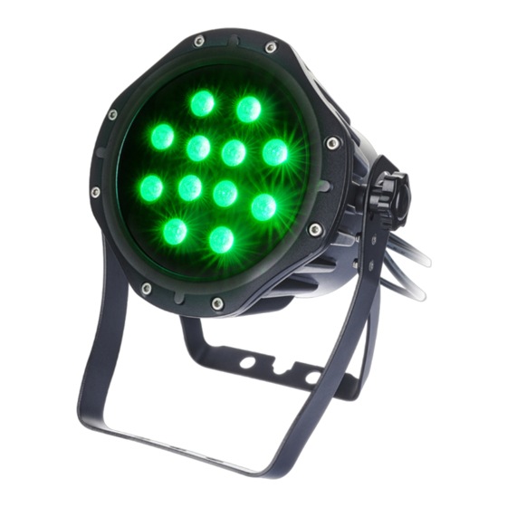
Features Features Due to its sturdy and weather-proof housing made of die-cast aluminium, the Outdoor Stage PAR 12 × 3W Tri is especially suitable for outdoor use. With the very bright three-colour LEDs, it is particularly suitable for professional lighting tasks. Special features of the device: 12 ×... - Page 16 Features Information about protection Equipment with protection class IP65 are dust-tight and completely protected against contact class IP65 (first code number). They are also protected against splash water from any angle (second code digit). That is why this equipment can also be used outdoors. Event technology equipment is generally only designed for temporary use however (event lighting) and not for permanent use outdoors.
-
Page 17: Installation
Installation Installation Unpack and check carefully there is no transportation damage before using the unit. Keep the equipment packaging. To fully protect the product against vibration, dust and moisture during transportation or storage use the original packaging or your own packaging material suitable for transport or storage, respectively. - Page 18 Installation NOTICE! Risk of overheating Always ensure sufficient ventilation. The ambient temperature must not exceed the limits stated in the chapter Tech‐ nical Specifications of the User Manual. NOTICE! Use of stands When mounting the device onto a stand, ensure that the stand is in a safe and stable position and that the weight of the device does not exceed the maximum permissible load capacity of the stand.
- Page 19 Possible damage due to moisture Moisture entering into open connectors (plugs and couplers) of DMX or power cords can cause short circuits. Close unused connectors with end caps intended for this purpose (www.thomann.de). Outdoor Stage PAR 12 × 3W Tri...
- Page 20 Installation Mounting options You can install the unit in hanging or standing position. When in use, the device must always be attached to a solid surface or an approved truss. Benutzen Sie zur Befestigung die dafür vor‐ gesehenen Öffnungen des zweiteiligen Bügels. Always work from a stable platform whenever installing, moving or servicing the unit.
- Page 21 Installation Connecting the DMX IP65 con‐ nectors Proceed as follows to connect the DMX-IP65 connectors: Insert the plug completely and straight into the coupling. Make sure that the flexible sealing ring has complete contact. Turn the union nut straight onto the thread of the coupling. Hand-tighten the union nut. Outdoor Stage PAR 12 ×...
-
Page 22: Starting Up
Starting up Starting up Create all connections while the device is off. Use the shortest possible high-quality cables for all connections. Take care when running the cables to prevent tripping hazards. LED PAR... - Page 23 Starting up Connections in DMX mode Connect the DMX input of the device to the DMX output of a DMX controller or another DMX device. Connect the output of the first DMX device to the input of the second one, and so on to form a daisy chain.
- Page 24 Starting up Connections in ‘Master / When you configure a group of devices in ‘Master / Slave’ mode, the first unit will control the Slave‘ mode others. This feature is especially useful to start a show without much programming. Connect the DMX output of the master unit to the DMX input of the first slave unit.
-
Page 25: Connections And Operating Elements
Connections and operating elements Connections and operating elements Rear panel Outdoor Stage PAR 12 × 3W Tri... - Page 26 Connections and operating elements 1 [Power In] Mains cable for the power supply of the device. 2 [Power Out] Power cord for the voltage supply of a connected device. 3 [DMX IN] DMX input cable 4 [DMX OUT] DMX output cable 5 Pressure equalisation element 6 Display 7 [Down]...
- Page 27 Connections and operating elements 9 [Setup] Selects an option of the respective operating mode. 10 [Mode] Activates the main menu and toggles between menu items. 11 Locking screws for the retaining bracket 12 Retaining bracket Outdoor Stage PAR 12 × 3W Tri...
-
Page 28: Operating
Operating Operating 7.1 Starting the device Connect the device to the power supply to start operation. After a few seconds, the display indicates that a reset is in progress. The device is then ready for use. 7.2 Main menu Press [MODE] to activate the main menu and select an operating mode. Use [UP] and [DOWN] to change the respectively displayed value. - Page 29 Operating DMX mode Press [Mode] until the display shows ‘d.xxx’ . Now you can set the number of the first DMX channel to be used by the device (DMX address). Use [UP] and [DOWN] to select a value between 1 and 510 (display shows ‘d.001’ … ‘d.512’ ). Make sure that this number matches the configuration of your DMX controller.
- Page 30 Operating This setting is only relevant when the device is controlled via DMX. When the display shows the desired value, press [Setup] to confirm the selection and then [Mode] to return to the parent menu. To return to the parent menu without making changes, press [Mode]. LED PAR...
- Page 31 Operating Operating mode ‘Show/Master’ Press [Mode] repeatedly until the display shows ‘Pr.xx’ . Now you can select one of the 10 pre‐ programmed automatic shows. Use [UP] and [DOWN] to select a value between ‘Pr.01’ and ‘Pr.10’ . Program Description Pr.01 Constant colour hue Pr.02...
- Page 32 Operating The auto show can only be activated on the device that works as master. This setting is only relevant if the device is not controlled via DMX. The device can operate in stand-alone mode or control connected devices of the same type, that must be configured as slaves.
- Page 33 Operating Settings programme Pr.01 For programme ‘Pr.01’ , you can choose from three full colours and four mixed colours. Select programme ‘Pr.01’ first, then confirm with ‘Setup’ . Now you can use the [UP] and [DOWN] but‐ tons to select one of the following options: Value Description 1.--r...
- Page 34 Operating Settings programme Pr.02 … For programmes ‘Pr.02’ to ‘Pr.01’ , you can additionally set the speed for the transition from Pr.10 one hue to the next. Use [UP] and [DOWN] to select a value between ‘slow’ and ‘fast’ (display shows ‘d.001’...
- Page 35 Operating Operating mode ‘Slave’ Press [Mode] until the display shows ‘SLAv’ . Confirm with [Setup]. This setting is only relevant if the device is operating as Slave controlled by a Master, but not via DMX. When the display shows the desired value, press [Setup] to confirm the selection and then [Mode] to return to the parent menu.
-
Page 36: Menu Overview
Operating 7.3 Menu overview LED PAR... -
Page 37: Functions In 3-Channel Dmx Mode
Operating 7.4 Functions in 3-channel DMX mode Channel Value Function 0…255 Intensity red (0 % to 100 %) 0…255 Intensity green (0 % to 100 %) 0…255 Intensity blue (0 % to 100 %) 7.5 Functions in 4-channel DMX mode Channel Value Function... -
Page 38: Functions In 8-Channel Dmx Mode
Operating 7.6 Functions in 8-channel DMX mode In 8-channel DMX mode, you can assign a device ID in the range from ‘Id.01’ to ‘Id.66’ via DMX menu ( Ä ‘DMX mode’ on page 29). By assigning such an ID, several devices that work with the same DMX address can be grouped. - Page 39 Operating Channel Value Function 36…44 Red: 200, Green: 255 45…53 Red: 100, Green: 255 54…62 Red: 40, Green: 255 63…71 Green: 255 72…80 Green: 255, Blue: 50 81…89 Green: 255, Blue: 150 90…98 Green: 255, Blue: 255 99…107 Green: 150, Blue: 255 108…116 Green: 50, Blue: 255 117…125...
- Page 40 Operating Channel Value Function 153…161 Red: 220, Blue: 50 162…170 Red: 150, Green: 50, Blue: 100 171…179 Red: 50, Green: 180, Blue: 220 180…188 Red: 50, Green: 220, Blue: 100 189…197 Red: 150, Green: 220 198…206 Red: 150, Blue: 220 207…215 Green: 180, Blue: 220 216…224...
- Page 41 Operating Channel Value Function 0…255 Slow…fast Channel 6 = 0 Intensity Green 0…255 (0 % to 100 %) Channel 6 = 1… Without function Channel 6 = 0 Intensity Blue 0…255 (0 % to 100 %) Channel 6 = 1… Without function 0…9 Without function...
- Page 42 Operating Channel Value Function 100…124 Pr.05 125…149 Pr.06 150…174 Pr.07 175…199 Pr.08 200…224 Pr.09 225…255 Pr.10 Control of all devices that use the same DMX address 0…9 All IDs 10…19 20…29 … 200…209 ID20 ID21 LED PAR...
- Page 43 Operating Channel Value Function ID22 … ID66 0…250 Fast response faders 1, 2, 3 and 4 251…255 Delayed response faders 1, 2, 3 and 4 Outdoor Stage PAR 12 × 3W Tri...
-
Page 44: Technical Specifications
Technical specifications Technical specifications LEDs 12 × tri-colour LEDs, 3 W Beam angle 30 ° Number of DMX channels 3, 4, 8 Operating supply voltage AC 110…230 V 50/60 Hz Power consumption 42 W Protection class IP65 Temperature range –20 °C … +45 °C Dimensions (W ×... -
Page 45: Plug And Connection Assignments
Plug and connection assignments Plug and connection assignments Introduction This chapter will help you select the right cables and plugs to connect your valuable equip‐ ment so that a perfect light experience is guaranteed. Please take our tips, because especially in ‘Sound & Light’ caution is indicated: Even if a plug fits into a socket, the result of an incorrect connection may be a destroyed DMX controller, a short circuit or ‘just’... -
Page 46: Troubleshooting
Troubleshooting Troubleshooting NOTICE! Possible data transmission errors For error-free operation make use of dedicated DMX cables and do not use ordi‐ nary microphone cables. Never connect the DMX input or output to audio devices such as mixers or ampli‐ fiers. In the following we list a few common problems that may occur during operation. - Page 47 DMX interface circuits. If the procedures recommended above do not succeed, please contact our Service Center. You can find the contact information at www.thomann.de. Outdoor Stage PAR 12 × 3W Tri...
-
Page 48: Cleaning
Cleaning Cleaning Optical lenses Clean the optical lenses, that are accessible from the outside, regularly in order to optimize the light output. The frequency of cleaning depends on the operating environment: wet, smoky or particularly dirty surroundings can cause more accumulation of dirt on the optics of the device. -
Page 49: Protecting The Environment
Protecting the environment Protecting the environment Disposal of the packaging mate‐ rial For the transport and protective packaging, environmentally friendly materials have been chosen that can be supplied to normal recycling. Ensure that plastic bags, packaging, etc. are properly disposed of. Do not just dispose of these materials with your normal household waste, but make sure that they are collected for recycling. - Page 50 Notes LED PAR...
- Page 52 Musikhaus Thomann · Hans-Thomann-Straße 1 · 96138 Burgebrach · Germany · www.thomann.de...
Need help?
Do you have a question about the STAIRVILLE Outdoor Stage PAR 12 X 3W Tri and is the answer not in the manual?
Questions and answers