Table of Contents
Advertisement
Advertisement
Table of Contents

Related Manuals for thomann VARYTEC Bull 200 IP


Summary of Contents for thomann VARYTEC Bull 200 IP
- Page 1 Bull 200 IP LED Spotlight...
- Page 2 Thomann GmbH Hans-Thomann-Straße 1 96138 Burgebrach Germany Telephone: +49 (0) 9546 9223-0 Internet: www.thomann.de 28.11.2022, ID: 554028...
-
Page 3: Table Of Contents
Table of contents Table of contents General information..........................5 1.1 Further information........................... 6 1.2 Notational conventions........................6 1.3 Symbols and signal words....................... 7 Safety instructions..........................10 Features............................... 13 Installation..............................15 Starting up..............................18 Connections and controls........................20 Operating..............................22 7.1 Starting the device........................... 22 7.2 Operating on the unit........................ - Page 4 Table of contents Plug and connection assignments....................42 Troubleshooting............................43 Cleaning............................... 45 Protecting the environment......................46 Bull 200 IP LED Spotlight...
-
Page 5: General Information
Our products and user manuals are subject to a process of continuous development. We there‐ fore reserve the right to make changes without notice. Please refer to the latest version of the user manual which is ready for download under www.thomann.de. Bull 200 IP... -
Page 6: Further Information
General information 1.1 Further information On our website (www.thomann.de) you will find lots of further information and details on the following points: Download This manual is also available as PDF file for you to download. Use the search function in the electronic version to find the topics of Keyword search interest for you quickly. -
Page 7: Symbols And Signal Words
General information Letterings The letterings for connectors and controls are marked by square brackets and italics. Examples: [VOLUME] control, [Mono] button. Displays Texts and values displayed on the device are marked by quotation marks and italics. Examples: ‘24ch’ , ‘OFF’ . Instructions The individual steps of an instruction are numbered consecutively. - Page 8 General information Signal word Meaning DANGER! This combination of symbol and signal word indicates an immediate dangerous situation that will result in death or serious injury if it is not avoided. WARNING! This combination of symbol and signal word indicates a pos‐ sible dangerous situation that can result in death or serious injury if it is not avoided.
- Page 9 General information Warning signs Type of danger Warning – suspended load. Warning – danger zone. Bull 200 IP LED Spotlight...
-
Page 10: Safety Instructions
Safety instructions Safety instructions Intended use This device is intended for use as an electronic lighting effect by means of LED technology. The device is designed for professional use only and is not suitable for use in households. Use the device only as described in this user manual. - Page 11 Safety instructions DANGER! Electric shock caused by short-circuit Always use proper ready-made insulated mains cabling (power cord). Do not modify the mains cable. Failure to do so could result in electric shock/death or fire. If in doubt, seek advice from a registered electrician. DANGER! Electric shock caused by high voltages inside Within the device there are areas where high voltages may be present.
- Page 12 Safety instructions NOTICE! Power supply Before connecting the device, ensure that the input voltage (AC outlet) matches the voltage rating of the device and that the AC outlet is protected by a residual current circuit breaker. Failure to do so could result in damage to the device and possibly injure the user.
-
Page 13: Features
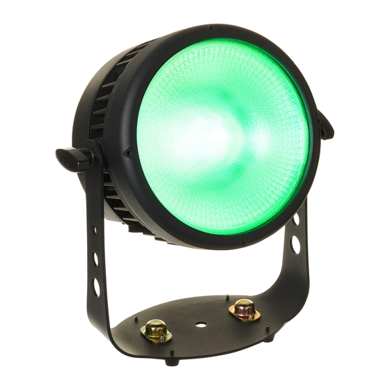
Features Features The fanless spotlight is suitable for demanding outdoor use as well as for TV and theatre. Special features of the device: 1 × 4in1 RGBWW COB LED (200 W each) Control via DMX (3 modes) or via buttons and display on the unit Large beam angle with even light spread Four selectable dimmer curves and halogen dimming behaviour Flicker-free PWM dimming... - Page 14 Features The specified protection class does not make a statement about the weather resistance of the equipment (resistance to changing ambient conditions as well as against the effects of sun‐ light and UV rays). The seals and screw connections of the equipment must be checked regularly to ensure a fault-free operation.
-
Page 15: Installation
Installation Installation Unpack and check carefully there is no transportation damage before using the unit. Keep the equipment packaging. To fully protect the product against vibration, dust and moisture during transportation or storage use the original packaging or your own packaging material suitable for transport or storage, respectively. - Page 16 NOTICE! Possible damage due to moisture Moisture entering into open connectors (plugs and couplers) of DMX or power cords can cause short circuits. Close unused connectors with end caps intended for this purpose (www.thomann.de). Bull 200 IP LED Spotlight...
- Page 17 Installation Mounting options You can install the device in hanging or standing position. When in use, the device must always be attached to a solid surface or an approved truss. Use the openings of the bracket provided for mounting. Always work from a stable platform whenever installing, moving or servicing the device. In doing so, the area underneath the device must be cordoned off.
-
Page 18: Starting Up
Starting up Starting up Create all connections while the device is off. Use the shortest possible high-quality cables for all connections. Take care when running the cables to prevent tripping hazards. Connections in DMX mode Connect the DMX input of the device to the DMX output of a DMX controller or another DMX device. - Page 19 Starting up Connections in master/slave When you configure a group of devices in master/slave mode, the first unit will control the mode other units for an automatic, sound-activated, synchronized show. This function is ideal when you want to start a show immediately. Connect the DMX output of the master device to the DMX input of the first slave device.
-
Page 20: Connections And Controls
Connections and controls Connections and controls & ' ö Bull 200 IP PUSH MENU DOWN ENTER Bull 200 IP LED Spotlight... - Page 21 Connections and controls 1 Bracket for floor placement or hanging 2 Locking screws for the brackets. 3 Pressure compensation element 4 Display and function buttons. [MENU] | calls up the settings menu, skips one menu level back and closes an opened submenu without saving any changes.
-
Page 22: Operating
Operating Operating 7.1 Starting the device Connect the device to the power supply to start operation. The LED lights. The device is imme‐ diately operational. 7.2 Operating on the unit Navigating in the menu Press [MENU] to activate the main menu. Press [UP] or [DOWN] to call up further menu items. - Page 23 Operating 7.2.1 DMX address This setting is only relevant if the device is controlled via a DMX controller. Press [MENU] to activate the main menu. Press [UP] or [DOWN] repeatedly until the display shows ‘DMX’ . Confirm with [ENTER]. Use [UP] or [DOWN] to select the desired DMX address between ‘001’ and ‘512’ . Confirm with [ENTER].
- Page 24 Operating 7.2.2 DMX mode This setting is only relevant if the device is controlled via a DMX controller. Press [MENU] to activate the main menu. Press [UP] or [DOWN] repeatedly until the display shows ‘Mode’ . Confirm with [ENTER]. Press [UP] or [DOWN] repeatedly until the display shows ‘DMX’ . Confirm with [ENTER]. Use [UP] or [DOWN] to select the desired DMX mode ‘(4Ch’...
- Page 25 Operating 7.2.3 Selecting and configuring automatic programmes In this operating mode you select an automatic programme and configure the running speed of the automatic programme. This operating mode can only be activated when the device is operating in stand alone mode or as master in a master / slave combination. This setting is only relevant if the device is not controlled via a DMX Press [MENU] to activate the main menu.
- Page 26 Operating 7.2.4 Sound control In this mode, the unit follows the rhythm of the background music or sounds detected by the built-in microphone. Press [MENU] to activate the main menu. Press [UP] or [DOWN] repeatedly until the display shows ‘Mode’ . Confirm with [ENTER]. Press [UP] or [DOWN] repeatedly until the display shows ‘Sound’...
- Page 27 Operating 7.2.5 Constant colours and colour macros This setting can only be made when the device is operating in stand alone mode or as master in a master / slave combination. This setting is only relevant if the device is not controlled via a DMX controller.
- Page 28 Operating 7.2.6 Enabling Slave mode This setting can only be made when the device is operating in stand alone mode or as master in a master / slave combination. This setting is only relevant if the device is not controlled via a DMX controller.
-
Page 29: System Settings
Operating 7.3 System settings 7.3.1 Setting display illumination Press [MENU] to activate the main menu. Press [UP] or [DOWN] repeatedly until the display shows ‘Mode’ . Confirm with [ENTER]. Press [UP] or [DOWN] repeatedly until the display shows ‘Display’ . Confirm with [ENTER]. Use [UP] or [DOWN] to select ‘On’... - Page 30 Operating 7.3.3 Power saving mode Press [MENU] to activate the main menu. Press [UP] or [DOWN] repeatedly until the display shows ‘Mode’ . Confirm with [ENTER]. Press [UP] or [DOWN] repeatedly until the display shows ‘Limiter’ . Confirm with [ENTER]. Use [UP] or [DOWN] to select ‘On’...
- Page 31 Operating 7.3.5 PWM (pulse width modulation) Press [MENU] to activate the main menu. Press [UP] or [DOWN] repeatedly until the display shows ‘Mode’ . Confirm with [ENTER]. Press [UP] or [DOWN] repeatedly until the display shows ‘Frequency’ . Confirm with [ENTER].
- Page 32 Operating 7.3.6 Setting the dimmer response Press [MENU] to activate the main menu. Press [UP] or [DOWN] repeatedly until the display shows ‘Mode’ . Confirm with [ENTER]. Press [UP] or [DOWN] repeatedly until the display shows ‘Dim Response’ . Confirm with [ENTER].
- Page 33 Operating 7.3.7 Dimmer curve Press [MENU] to activate the main menu. Press [UP] or [DOWN] repeatedly until the display shows ‘Mode’ . Confirm with [ENTER]. Press [UP] or [DOWN] repeatedly until the display shows ‘Dimmer Curve’ . Confirm with [ENTER]. Use [UP] or [DOWN] to select the desired dimmer curve.
-
Page 34: System Information
Operating 7.4 System information 7.4.1 Firmware version Press [MENU] to activate the main menu. Press [UP] or [DOWN] repeatedly until the display shows ‘Information’ . Confirm with [ENTER]. Press [UP] or [DOWN] repeatedly until the display shows ‘Firmware’ . Confirm with [ENTER]. - Page 35 Operating 7.4.3 Device temperature Press [MENU] to activate the main menu. Press [UP] or [DOWN] repeatedly until the display shows ‘Information’ . Confirm with [ENTER]. Press [UP] or [DOWN] repeatedly until the display shows ‘Temperature’ . Confirm with [ENTER]. ð The device temperature. is displayed. Bull 200 IP LED Spotlight...
-
Page 36: Menu Overview
Operating 7.5 Menu overview Mode Information 001...512 Display Dim Response Firmware Fast Ver1.0 Standard TimeInfo Halogen Display Rev Auto Dimmer Curve Temperature Step Sp00...Sp99 Linear Prog Sp00...Sp99 Limiter Fade Sp00...Sp99 S-Curve Sound Step Se00...Se99 DMX Fail Fade Se00...Se99 Blackout Static Hold Dimmer 000...255... -
Page 37: Functions In 4-Channel Dmx Mode
Operating 7.6 Functions in 4-channel DMX mode Channel Value Function 000…255 Intensity red (0 %…100 %) 000…255 Intensity green (0 %…100 %) 000…255 Intensity blue (0 %…100 %) 000…255 Intensity white (0 %…100 %) Bull 200 IP LED Spotlight... -
Page 38: Functions In 6-Channel Dmx Mode
Operating 7.7 Functions in 6-channel DMX mode Channel Value Function 000…255 Intensity red (0 %…100 %) 000…255 Intensity green (0 %…100 %) 000…255 Intensity blue (0 %…100 %) 000…255 Intensity white (0 %…100 %) 000…255 Master dimmer (0 %…100 %) 000…255 Strobe effect, increasing speed Bull 200 IP... -
Page 39: Functions In 8-Channel Dmx Mode
Operating 7.8 Functions in 8-channel DMX mode Channel Value Function 000…255 Master dimmer (0 %…100 %) 000…255 Strobe effect, increasing speed 000…255 Intensity red (0 %…100 %) 000…255 Intensity green (0 %…100 %) 000…255 Intensity blue (0 %…100 %) 000…255 Intensity white (0 %…100 %) 000…004 No function... -
Page 40: Technical Specifications
Technical specifications Technical specifications 281 mm Item no. Light source 4in1 RBGWW COB LED, 200 W Optical properties Beam angle 60 ° Control DMX, buttons and display Number of DMX channels 4, 6, 8 Input connections Power supply Lockable input socket Power Twist TR1 IP65 DMX control XLR chassis socket (IP65), 3-pin... - Page 41 Technical specifications Item no. Dimensions (W × H × D), with bracket 281 mm × 323 mm × 150 mm Weight 5.5 kg Ambient conditions Temperature range 0 °C…40 °C Relative humidity 20 %…80 % (non-condensing) Bull 200 IP LED Spotlight...
-
Page 42: Plug And Connection Assignments
Plug and connection assignments Plug and connection assignments Introduction This chapter will help you select the right cables and plugs to connect your valuable equip‐ ment so that a perfect light experience is guaranteed. Please take our tips, because especially in ‘Sound & Light’ caution is indicated: Even if a plug fits into a socket, the result of an incorrect connection may be a destroyed DMX controller, a short circuit or ‘just’... -
Page 43: Troubleshooting
Troubleshooting Troubleshooting NOTICE! Possible data transmission errors For error-free operation make use of dedicated DMX cables and do not use ordi‐ nary microphone cables. Never connect the DMX input or output to audio devices such as mixers or ampli‐ fiers. In the following we list a few common problems that may occur during operation. - Page 44 DMX interface circuits. If the procedures recommended above do not succeed, please contact our Service Center. You can find the contact information at www.thomann.de. Bull 200 IP LED Spotlight...
-
Page 45: Cleaning
Cleaning Cleaning Optical lenses Clean the optical lenses, that are accessible from the outside, regularly in order to optimize the light output. The frequency of cleaning depends on the operating environment: wet, smoky or particularly dirty surroundings can cause more accumulation of dirt on the optics of the device. -
Page 46: Protecting The Environment
Protecting the environment Protecting the environment Disposal of the packaging mate‐ rial For the transport and protective packaging, environmentally friendly materials have been chosen that can be supplied to normal recycling. Ensure that plastic bags, packaging, etc. are properly disposed of. Do not just dispose of these materials with your normal household waste, but make sure that they are collected for recycling. - Page 48 Musikhaus Thomann · Hans-Thomann-Straße 1 · 96138 Burgebrach · Germany · www.thomann.de...
Need help?
Do you have a question about the VARYTEC Bull 200 IP and is the answer not in the manual?
Questions and answers