Table of Contents
Advertisement
Quick Links
SCC Inc.
LMV5 Series
OCI415.30
for use with LMV5... Linkageless Burner Management Systems
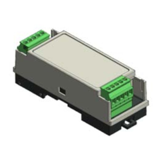
Description
OCI415.30
The OCI415.30 provides the LMV5... family of flame controllers
with a Modbus RTU or BACnet MS/TP interface. This allows the
interconnection of one or more LMV5... to a PLC or building
management system (BMS).
Installation Instructions
Document No. LV5‐6100
February 12, 2018
SCC Inc.
Advertisement
Table of Contents

Subscribe to Our Youtube Channel
Related Manuals for SCC OCI415.30


Summary of Contents for SCC OCI415.30
- Page 1 SCC Inc. Installation Instructions Document No. LV5‐6100 February 12, 2018 LMV5 Series OCI415.30 for use with LMV5... Linkageless Burner Management Systems OCI415.30 Description The OCI415.30 provides the LMV5... family of flame controllers with a Modbus RTU or BACnet MS/TP interface. This allows the interconnection of one or more LMV5... to a PLC or building management system (BMS). ...
-
Page 2: Table Of Contents
Compatible Controls ........................ 3 Linkageless Burner Management Systems ................. 3 Physical Connections ........................ 4 Power .......................... 4 Connection to LMV5 ...................... 4 Connection to BMS ...................... 5 Status LED ........................... 5 Tx/Rx LED .......................... 5 Required LMV5 Configuration .................... 6 Modbus RTU Connection Details.................... 7 BACnet MS/TP Connection Details ..................... 8 Configuration Utility ........................ 9 Using the Configuration Utility ................... 9 Updating Firmware ...................... 11 Modbus RTU Mapping ...................... 12 BACnet MS/TP Mapping ...................... 13 Page 2 SCC Inc. ... -
Page 3: Compatible Controls
LMV5 Series Installation Instructions Document No. LV5‐6100 Compatible Controls Linkageless Burner Management Systems LMV51... LMV52... SCC Inc. Page 3 ... -
Page 4: Physical Connections
Installation Instructions LMV5 Series Document No. LV5‐6100 Physical Connections Power Power to the OCI415.30 must be either 9‐24VDC or 9‐24VAC (nominal). Power consumption is 2.5W or less. SCC part number AGA15‐24 is available as a suitable power supply. Terminal designations: Label Function L+ DC + / AC ~ N‐ DC ‐ / AC ~ Connection to LMV5... The connection from the OCI415.30 to the LMV5… should be made with the supplied cable. The connection at the LMV5… is to the AZL X72 (COM2) port. Maximum allowed cable length is 5 meters. Page 4 SCC Inc. ... -
Page 5: Connection To Bms
LMV5 Series Installation Instructions Document No. LV5‐6100 Physical Connections (continued) Connection to BMS The connection from the BMS to the OCI415.30 is via terminal block. The physical medium is RS‐485. Multiple RS‐485 nodes may be connected in a daisy‐chain. For long runs (typically greater than 1000 feet) or noisy environments, termination may be required on the end node. Terminal designations: Label Function A RS‐485 Data (+) B RS‐485 Data (‐) G RS‐485 Common Ground Status LED The status LED annunciates the status of the OCI415.30 and the connection to the LMV5… Color Status Green Flashing No Connection to LMV5… Green / Red Alternating Communicating with LMV5… Red Flashing Internal Error OCI415.30 ... -
Page 6: Required Lmv5 Configuration
When a parameter needs to be changed, the Select < and Select > buttons allow the value to be changed and Enter confirms the change. Press the Esc button to return after the change is made. First, activate the Modbus port on the AZL (no password required): 1. Operation > OptgModeSelect > Type of Gateway = Modbus 2. Operation > OptgModeSelect > GatewayBASon Note: Older AZL units may read 'GatewayDDCon' instead. 3. The AZL should now read 'Gateway Mode active'. Next, set up the required parameters through the AZL (no password required): 1. Params & Display > Access w‐out PW > AZL > Modbus > Address = 1 2. Params & Display > Access w‐out PW > AZL > Modbus > Baudrate = 19200 bit/s 3. Params & Display > Access w‐out PW > AZL > Modbus > Parity = no 4. Params & Display > Access w‐out PW > AZL > Modbus > Timeout = 30s If remote operation is desired the load controller operating mode must be changed to “IntLC Bus” using the following procedure (no password required): 1. Params & Display > Access w‐out PW > LoadController > Configuration > LC_OptgMode = IntLC Bus The changes take effect immediately (no reboot required). Page 6 SCC Inc. ... -
Page 7: Modbus Rtu Connection Details
LMV5 Series Installation Instructions Document No. LV5‐6100 Modbus RTU Connection Details Modbus RTU protocol selection and addressing is done using the PC tool OCI Configuration Utility (see next section). Supported addresses: 1‐247 Supported baud rates: 2400, 4800, 9600, 19200, 38400, 57600, and 115200 Supported data bits: 8 Supported parity and stop bits: none (1 or 2 stop bits), odd (1 stop bit), and even (1 stop bit) Supported function codes: 3 (read holding registers), 4 (read input registers), 6 (write single holding register), and 16 (write multiple holding registers) Maximum read length: 125 (if beginning and ending registers are valid addresses) SCC Inc. Page 7 ... -
Page 8: Bacnet Ms/Tp Connection Details
Installation Instructions LMV5 Series Document No. LV5‐6100 BACnet MS/TP Connection Details BACnet MS/TP protocol selection and addressing is done using the PC tool OCI Configuration Utility (see next section). Supported addresses: 0‐127 Supported baud rates: 9600, 19200, 38400, 57600, 76800, and 115200 Supported data bits: 8 Supported parity and stop bits: none (1 stop bit) Supported device instances: 0‐4194302 Page 8 SCC Inc. ... -
Page 9: Configuration Utility
LMV5 Series Installation Instructions Document No. LV5‐6100 Configuration Utility Using the Configuration Utility 1. Double‐click the icon to open the configuration utility. 2. The utility will open and show the connection status of the OCI415.30. SCC Inc. Page 9 ... - Page 10 Installation Instructions LMV5 Series Document No. LV5‐6100 Configuration Utility (continued) 3. Use a mini‐USB cable to connect the OCI415.30 to the computer, such as SCC part number AGA5‐05M. A driver may self‐install the first time a connection is made. The connected device will then be indicated on the screen. 4. The protocol can be changed between Modbus RTU and BACnet MS/TP from this screen. See the previous sections for further details on the protocol‐specific settings that can be changed. Once the desired settings have been entered, click Submit to apply. Click Reload to refresh the displayed settings. Page 10 SCC Inc. ...
-
Page 11: Updating Firmware
LMV5 Series Installation Instructions Document No. LV5‐6100 Configuration Utility (continued) Updating Firmware 1. From the OCI415.30 Configuration Utility, click File ‐> Update Device… 2. Locate the supplied update file with a .duf extension and click Open. 3. The device will automatically reboot and reconnect with the OCI415.30 Configuration Utility once the firmware update is complete. When a device is connected, the firmware version is shown as one of the read‐only parameters. SCC Inc. Page 11 ... -
Page 12: Modbus Rtu Mapping
Installation Instructions LMV5 Series Document No. LV5‐6100 Modbus RTU Mapping (continued) Refer to Document No. LV5‐1000 (LMV5 Technical Instructions) for complete Modbus mapping information. Page 12 SCC Inc. ... -
Page 13: Bacnet Ms/Tp Mapping
NO UNITS ‐ ‐ MINUTE ANALOG INPUT 41 NO UNITS ‐ ‐ SECOND ANALOG INPUT 42 NO UNITS ‐ ‐ HOURS GAS RESET (SEE NOTE 6) ANALOG VALUE 43 HOURS ‐ ‐ HRS OIL S1 RESET (SEE NOTE 6) ANALOG VALUE 44 HOURS ‐ ‐ HRS OIL S2 RESET (SEE NOTE 6) ANALOG VALUE 45 HOURS ‐ ‐ SCC Inc. Page 13 ... - Page 14 ‐ OIL GAS UNIT TYPE BINARY INPUT 2 ‐ STANDARD METRIC CONTROL SWITCH BINARY INPUT 3 ‐ ON OFF FAN CONTACTOR BINARY INPUT 4 ‐ ON OFF OIL SELECTED BINARY INPUT 5 ‐ ON OFF GAS SELECTED BINARY INPUT 6 ‐ ON OFF Page 14 SCC Inc. ...
- Page 15 GAS Note 1 – Sensor type. 0: Pt100 1: Pt1000 2: Ni1000 3: Temperature (4‐20mA, 0‐10V) 4: Pressure (4‐20mA, 0‐10V) 5: Pt100Pt1000 6: Pt100Ni1000 7: No sensor Note 2 – LMV program stop. 0: deactivated 1: prepurge phase 24 2: ignition position phase 36 3: interval 1 phase 44 4: interval 2 phase 52 SCC Inc. Page 15 ...
- Page 16 0: Automatic 1: Burner on 2: Burner off Note 5 – Set local/remote (AV29) to 1 for remote. Once in remote the desired mode can be set using AV31 (0 = local/automatic, 1 = burner on, 2 = burner off). If AV31 is set to automatic, write the desired setpoint using AV32. If AV31 is set to burner on, write the desired firing rate using AV33. The firing rate must be between 0% and 100% to remain valid. AV29 must be actively written at least once during the timeout period to reset the timeout counter. Once the timeout counter reaches the timeout value local/remote will revert to local (failsafe operation). Note 6 – Counter values can only be reset to zero. Note 7 – There are 9 lockouts in memory (current plus 8 history). There are 21 errors in memory (current plus 20 history). The addresses for the historical data are all in the same format as shown in the mapping. Use the formula to find the correct instance. For example, the analog input instance for the ERROR CODE history index 4 would be (10 x 4) + 280 = 320, or AI320. The analog input instance for the LOCKOUT OUTPUT history index 7 would be (20 x 7) + 104 = 244, or AI244. Information in this publication is based on current specifications. The company reserves the right to make changes in specifications and models as design improvements are introduced. Product or company names mentioned herein may be the trademarks of their respective owners. © 2017 SCC Inc. Page 16 SCC Inc. ...
Need help?
Do you have a question about the OCI415.30 and is the answer not in the manual?
Questions and answers