Table of Contents
Advertisement
Quick Links
Advertisement
Table of Contents

Related Manuals for SCC MPPT 3KW


Summary of Contents for SCC MPPT 3KW
- Page 1 User Manual Solar Charge Controller 3KW...
-
Page 2: Table Of Contents
CONTENTS 1 ABOUT THIS MANUAL ................... 3 1.1 Purpose ...................... 3 1.2 Scope ......................3 1.3 SAFETY INSTRUCTIONS ................3 2 INTRODUCTION ....................4 2.1 Features...................... 4 2.2 Product Overview ..................5 3. INSTALLATION ..................... 6 3.1 Unpacking and Inspection ................6 3.2 Preparation .................... -
Page 3: About This Manual
1 ABOUT THIS MANUAL 1.1 Purpose This manual describes the assembly, installation, operation and troubleshooting of this unit. Please read this manual carefully before installations and operations. Keep this manual for future reference. 1.2 Scope This manual provides safety and installation guidelines as well as information on tools and wiring. -
Page 4: Introduction
2 INTRODUCTION Thank you for selecting this solar charge controller. This solar charge controller is an advanced solar charger with maximum power point tracking. Applying intelligent MPPT algorithm, it allows solar charge controller to extract maximum power from solar arrays by finding the maximum power point of the array. The MPPT battery charging process has been optimized for long battery life and improved system performance. -
Page 5: Product Overview
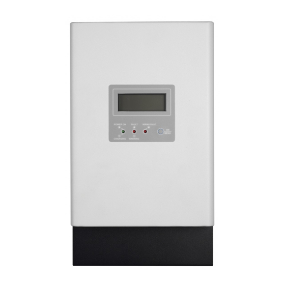
2.2 Product Overview 1. LCD display 2. Power On/Charging indicator 3. Fault and warning indicator 4. Wiring fault indicator 5. Operation button 6. PV connectors 7. Battery connectors 8. Battery voltage sense terminal 9. Remote temperature sensor terminal 10. Wiring box cover 11. -
Page 6: Installation
3. INSTALLATION 3.1 Unpacking and Inspection Before installation, please inspect the unit. Be sure that nothing inside the package is damaged. You should have received the following items inside of package: Solar charge controller x 1 User manual x 1 ... -
Page 7: Power Connection
Install the unit to the wall by screwing four screws. Refer to right chart. 3.4 Power Connection Wire size The four large power terminals are sized for 14 - 2 AWG (2.5 - 35 ) wire. The terminals are rated for copper and aluminum conductors. - Page 8 Connect the Power Wires WARNING: Shock Hazard The solar modules can produce open-circuit voltages in excess of 100 Vdc when in sunlight. Verify if solar input breaker or disconnect has been opened (disconnected) before connecting system wires. Connect terminals by following below steps (Refer to diagram above): 1.
-
Page 9: Grounding And Ground Fault Interruption
to the controller. 4. Connect positive terminal (+) of battery to the battery positive terminal (+) on the controller. 5. Connect negative terminal (-) of battery to one of the Common Negative terminals (-) on the controller. WARNING: Risk of Damage Be sure that solar connection is made with correct polarity. -
Page 10: Battery Voltage Sense
The RTS cable may be pulled through conduit along with the power wires. Tighten the connector screws with 5 in-lb (0.56 Nm) torque. NOTE: The RTS is optional package. Please check local dealer for the details. CAUTION: The controller will not activate temperature compensate charging function if the RTS is not used. -
Page 11: Communication Connections
A battery voltage sense connection is not essential required to operate your controller, but it is recommended for best performance. The battery voltage sense will ensure that the voltage display in LCD is very accurate. The voltage sense wires should be cut to length as required to connect the battery to the voltage sense terminal. - Page 12 Insert bundled software CD into a computer and follow on-screen instruction to install the monitoring software. For the detailed software operation, please check user manual of software inside of CD.
-
Page 13: Operation
4. OPERATION 4.1 Power-Up WARNING: Risk of Damage Connecting the solar module to the battery connector will permanently damage the controller. Confirm that the solar and battery polarities are correctly connected to the controller. A battery must be connected to the controller before operating it. The controller ... -
Page 14: Lcd Display Icons
Operation Button Function Action Description Power on Press the button until LCD backlight is on. Enter Press the button for 5 seconds until it jumps to next screen. Select Press shortly to change selection. If nothing to press in setting menu for 5 seconds, it will Exit automatically save current setting and exit the setting mode. - Page 15 Indicate charging current. Indicates battery level by 0-24%, 25-49%, 50-74% and 75-100% in battery mode and charging status in line mode. Battery Charging Status. Status Battery voltage LCD Display <2V/cell 4 bars will flash in turns. Constant The right bar will be on and the 2 ~ 2.083V/cell other three bars will flash in turns.
-
Page 16: Lcd Setting
4.3 Charging Current Setting After pressing and holding the button for 5 seconds, the unit will enter setting mode. Only charging current is able to set up. Press button shortly to switch setting current figure from C1 to C6, presenting 10A to 60A. After retaining in setting figure and nothing to press for 5 second, it will exit setting mode. -
Page 17: Specifications
5. TROUBLE SHOOTING Situation Fault Solution Fault Event Code Restart the charger. Over charge current If the problem remains, please contact your installer. Keep the charger in the cool environment. Over temperature If the problem remains, please contact your installer. Check the battery wire connection. - Page 18 6. SPECIFICATIONS Table 1 Electrical Specifications MODEL MPPT 3KW Nominal System Voltage 12, 24, or 48 VDC Maximum Battery Current 60 Amps Maximum Solar Input 145V Voltage PV Array MPPT Voltage 60~115VDC Range 12 Volt--800 Watts Maximum Input Power 24 Volt--1600 Watts...
- Page 19 Charging Set points Absorption Stage Float Stage Flooded Battery 14.6V / 29.2V / 58.4V 13.5V / 27V / 54V AGM/Gel Battery 14.1V / 28.2V / 56.4V 13.5V / 27V / 54V Over-charging voltage 15V / 30V / 60V Over-charging 14.5V / 29V / 58V comeback voltage Battery defect voltage 8.5V / 17V / 34V...
Need help?
Do you have a question about the MPPT 3KW and is the answer not in the manual?
Questions and answers