Table of Contents
Advertisement
Quick Links
User Manual
Original Instructions
EtherNet/IP™Absolute Encoder
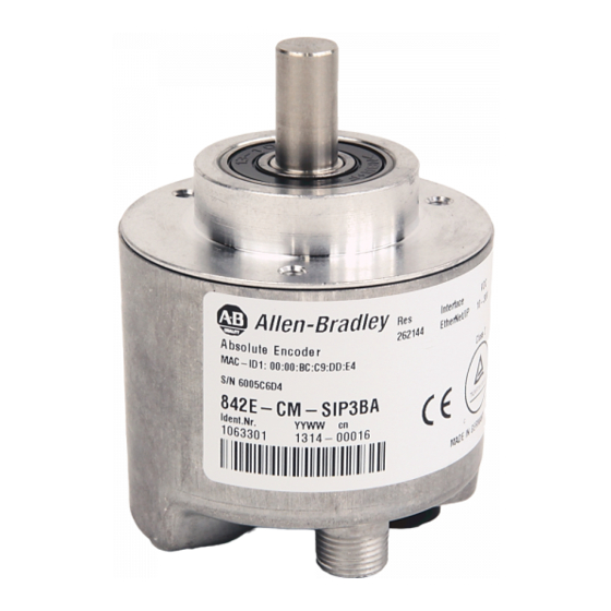
Catalog Numbers 842E-SIP1BA. 842E-SIP2BA, 842E-SIP3BA, 842E-SIP4BA, 842E-SIP5BA, 842E-SIP6BA, 842E-SIP7BA,
842E-SIP8BA, 842E-SIP9BA, 842E-SIP10BA, 842E-SIP11BA, 842E-SIP12BA, 842E-MIP1BA, 842E-MIP2BA, 842E-MIP3BA,
842E-MIP4BA, 842E-MIP5BA, 842E-MIP6BA, 842E-MIP7BA, 842E-MIP8BA, 842E-MIP9BA, 842E-MIP10BA, 842E-MIP11BA,
842E-MIP12BA
Advertisement
Table of Contents

Related Manuals for Allen-Bradley EtherNet/IP 842E-SIP1BA


Summary of Contents for Allen-Bradley EtherNet/IP 842E-SIP1BA
- Page 1 User Manual Original Instructions EtherNet/IP™Absolute Encoder Catalog Numbers 842E-SIP1BA. 842E-SIP2BA, 842E-SIP3BA, 842E-SIP4BA, 842E-SIP5BA, 842E-SIP6BA, 842E-SIP7BA, 842E-SIP8BA, 842E-SIP9BA, 842E-SIP10BA, 842E-SIP11BA, 842E-SIP12BA, 842E-MIP1BA, 842E-MIP2BA, 842E-MIP3BA, 842E-MIP4BA, 842E-MIP5BA, 842E-MIP6BA, 842E-MIP7BA, 842E-MIP8BA, 842E-MIP9BA, 842E-MIP10BA, 842E-MIP11BA, 842E-MIP12BA...
- Page 2 Important User Information Read this document and the documents listed in the additional resources section about installation, configuration, and operation of this equipment before you install, configure, operate, or maintain this product. Users are required to familiarize themselves with installation and wiring instructions in addition to requirements of all applicable codes, laws, and standards.
-
Page 3: Table Of Contents
Table of Contents Preface About This Document ......... .5 Who Should Use This Manual . - Page 4 Table of Contents Identity Object..........24 Assembly Object .
- Page 5 Table of Contents Chapter 7 Diagnostics and Troubleshooting Status Indicators ..........63 Self-test Via EtherNet/IP .
- Page 6 Table of Contents Notes: Rockwell Automation Publication 842E-UM001C-EN-P - September 2016...
-
Page 7: Preface
• Explains how to install and wire your encoder Related Documentation The following documents contain additional information concerning Rockwell Automation® products. To obtain a copy, contact your local Rockwell Automation® office or Allen-Bradley distributor. Resource Description Installation Instructions Pub. # 10000169360 842E EtherNet/IP Multi-turn Encoders EtherNet/IP Modules in Logix5000™... - Page 8 Preface Notes: Rockwell Automation Publication 842E-UM001C-EN-P - September 2016...
-
Page 9: Safety
Chapter Safety This chapter deals with your own safety and the safety of the equipment operators. Read this chapter carefully before working with the 842E EtherNet/IP encoder or the machine or system in which the 842E EtherNet/IP encoder is used. Authorized Personnel ATTENTION: Only authorized personnel can install, commission, and service the 842E EtherNet/IP encoder. -
Page 10: General Safety Notes And Protective Measures
Chapter 1 Safety necessary to comply with the EtherNet/IP specifications and guidelines for installing an EtherNet/IP network. If any modifications are made to the 842E EtherNet/IP encoder, any warranty claim against Rockwell Automation is rendered void. General Safety Notes and Protective Measures ATTENTION: Observe the following procedures to confirm the correct and proper use of the 842E EtherNet/IP encoder. -
Page 11: Encoder Overview
Chapter Encoder Overview The 842E family of encoders uses EtherNet/IP technology to provide its data to a programmable controller. These encoders include an embedded EtherNet/IP switch to connect additional EtherNet/IP capable products in series and/or support a Device Level Ring (DLR) topology for Ethernet media redundancy. -
Page 12: 842E Encoder Features
Chapter 2 Encoder Overview Multi-turn units assign a unique digital output for each shaft position across multiple shaft rotations and have high-resolution capability. Rockwell Automation absolute encoders are available with an enclosure rating of NEMA Type 4 and IP66, and various mounting options. Applications include steel mills, overhead cranes, punch presses, transfer lines, oil rigs, wind mills, machine tools, and packaging. -
Page 13: Configurable Parameters
Encoder Overview Chapter 2 Configurable Parameters The EtherNet/IP technology allows for certain encoder parameters to be configured over the network. • Count direction • Counts per revolution • Preset value • Velocity output • IP addressing The Electronic The electronic data sheet (EDS) file contains all information that is related to the measuring-system-specific parameters and the operating modes of the 842E Data Sheet File EtherNet/IP encoders. -
Page 14: Control Flash
Chapter 2 Encoder Overview Special Features Properties Encoder Single-turn Multi-turn ■ ■ Absolute Encoder in 60 mm (2.36 in.) design ■ ■ Robust nickel code disk for harsh environment ■ ■ High precision and reliability ■ ■ Ball bearings are spaced 30 mm (1.18 in.) apart ■... -
Page 15: Ethernet/Ip Overview
Chapter EtherNet/IP Overview Ethernet Industrial Protocol (EtherNet/IP) is a frame-based computer networking technology for local industrial area networks. It follows the seven layers of the Open Systems Interconnection model: OSI Model Host Layers Layer Function 7. Application Network process to application 6. -
Page 16: Tcp/Ip And Udp/Ip
Chapter 3 EtherNet/IP Overview The encoder is an I/O adapter in the EtherNet/IP. It receives and sends explicit and implicit messages either cyclic or on request (polled). TCP/IP and UDP/IP EtherNet/IP uses TCP/IP or UDP/IP for communication. (TCP is transmission control protocol and UDP is user datagram protocol.) Implicit messaging is used for real-time communication between a programmable logic controller (PLC) and the encoder in EtherNet/IP. -
Page 17: Understanding The Producer/Consumer Model
EtherNet/IP Overview Chapter 3 The Ethernet data field consists of several nested protocols: • The IP datagram is transported in the user data of the Ethernet data field. • The TCP segment or the UDP datagram is transported in the user data of the IP datagram. -
Page 18: Specifying The Requested Packet Interval
Chapter 3 EtherNet/IP Overview Specifying the Requested The requested packet interval (RPI) is the update rate that is specified for a particular piece of data on the network. This value specifies how often to Packet Interval produce the data for that device. For example, if you specify an RPI of 50 ms, it means that every 50 ms the device sends its data to the controller or the controller sends its data to the device. -
Page 19: Linear Topology
EtherNet/IP Overview Chapter 3 Linear Topology The linear topology uses the embedded switching capability to form a daisy- chain style network that has a beginning and an end. Linear topology simplifies installation and reduces wiring and installation costs, but a break in the network disconnects all devices downstream from the break. -
Page 20: Endless Shaft Functionality
Chapter 3 EtherNet/IP Overview Endless Shaft Functionality The endless-shaft feature is not supported for the single-turn encoder. This functionality is applicable only for the multi-turn Ethernet encoders and accessible only via messaging (not the AOP). The round axis functionality or endless shaft functionality removes the restriction that the total resolution must be 2 times the steps per revolution. - Page 21 EtherNet/IP Overview Chapter 3 Enabling Endless Shaft Functionality CIP message instructions must be used to configure the endless shaft functionality. The following attributes must be set for the functionality to be enabled. • Attribute ID 0Eh, Scaling must be set to 1. •...
- Page 22 Chapter 3 EtherNet/IP Overview Figure 8 Attribute 126 (7e hex) Nominator Figure 9 Attribute 127 (7f hex) Divisor Rockwell Automation Publication 842E-UM001C-EN-P - September 2016...
- Page 23 EtherNet/IP Overview Chapter 3 Figure 10 Attribute 17 (11 hex) Total measuring range Figure 11 Update your logic to verify that the encoder is in the RUNNING state before executing the message instruction to set the endless shaft attribute. Otherwise the attribute will not be maintained upon power cycle.
-
Page 24: Features
Chapter 3 EtherNet/IP Overview Figure 12 Features Attribute 14 (e hex) Scaling Function Control (SFC) Attribute 125 (7d hex) Endless Shaft Functionality (ESF) Attribute 126 (7e hex Nominator (CNR_N) Attribute 127 (7f hex)– Divisor (CNR_D) Attribute 17 (11 hex) Total Measuring Range (CMR) IMPORTANT Don’t make online scaling changes through the module profile unless the encoder device is inhibited. -
Page 25: Position Sensor Object
EtherNet/IP Overview Chapter 3 The 842E EtherNet/IP encoder supports the following classes of the encoder profile: Class Code Object Class Description Number of Instances 0x01 Identity object Contains information on the node within the network 0x02 Message router object Processes all messages and routes them to the appropriate objects 0x04 Assembly object... -
Page 26: Identity Object
Chapter 3 EtherNet/IP Overview See Appendix B on page for an example of how to use the position sensor object to create an explicit message in RSLogix 5000®. Identity Object The device information and device parameters are opened via the instances. 48h QoS 47h DLR 23h Position Sensor... - Page 27 EtherNet/IP Overview Chapter 3 Service Code Service Description Get_Attribute_All Returns the values of all attributes Get_Attribute_Single Returns the values of one attribute Reset Resets the device: 0 = The device is reinitialized (power on). 1 = The device is reinitialized (power on) and reset to the factory settings.
-
Page 28: Assembly Object
Chapter 3 EtherNet/IP Overview Name Description Default Value Major Recoverable 0 = No serious error Status 1 = Serious error that can be reset (device in error status) Major Unrecoverable 0 = No serious error Status 1 = Serious error that cannot be reset (device in error status) 12…15 —... -
Page 29: I/O Assembly
EtherNet/IP Overview Chapter 3 Service Code Service Description Get_Attribute_All Returns the values of all attributes Get_Attribute_Single Returns the values of one attribute Table 10 - Instance Services of the Assembly Object Instance Attribute Access Description Bits Bytes Position value Position value Warning and alarm flags Position value Velocity... -
Page 30: I/O
Chapter 3 EtherNet/IP Overview I/O Assembly The I/O data are retrieved/output via instances. 48 h QoS 47 h DLR 23 h Position Sensor 01h Identity 02h Message Router 04h Assembly Network 06h Connection Manager Figure 15 - Connections for the Configuration Assembly Instance Byte Bit 7... - Page 31 EtherNet/IP Overview Chapter 3 Instance Byte Bit 7 Bit 6 Bit 5 Bit 4 Bit 3 Bit 2 Bit 1 Bit 0 101/101WS Fault header (least significant byte, see Table XX on page XXX) Fault header Fault header Fault header (most significant byte) Position value (least significant byte) Position value Position value...
-
Page 32: Config
Chapter 3 EtherNet/IP Overview 48h QoS 47h DLR 23h Position Sensor 01h Identity 02h Message Router 04h Assembly Config Network 06h Connection Manager Figure 16 - Connections for the Configuration Assembly Rockwell Automation Publication 842E-UM001C-EN-P - September 2016... - Page 33 EtherNet/IP Overview Chapter 3 Instance Byte Bit 7 Bit 6 Bit 5 Bit 4 Bit 3 Bit 2 Bit 1 Bit 0 Not used Not used Not used Not used Steps per revolution CPR (least significant byte) CPR (most significant byte) Total resolution CMR (least significant byte) CMR (most significant byte) Not used...
- Page 34 Chapter 3 EtherNet/IP Overview Position Sensor Object Instance Service Name Description 0x05 Reset Restart with all EEPROM parameters of the encoder, restart with the factory defaults 00: Restart Object– read all EEPROM parameters 01: set and save factory defaults and restart object– read all EEPROM parameter 0x0E Get_Attribute_Single...
- Page 35 EtherNet/IP Overview Chapter 3 Attribute ID Attribute ID Access NV / Name Data type Description Min. / Max. (dec) (hex) rule (default) Number of attributes Number of supported attributes in this 0x0039 class Attribute list ARRAY List of supported attributes –...
- Page 36 Chapter 3 EtherNet/IP Overview Attribute ID Attribute ID Access NV / Name Data type Description Min. / Max. (dec) (hex) rule (default) Acceleration format Format of acceleration value (0x0810) UNIT 0x0810: cps/s 0x0811: rpm/s 0x0812: rps/s Acceleration resolution DINT Minimum resolution of acceleration (0x00 00 00 01) value Minimum acceleration setpoint...
- Page 37 EtherNet/IP Overview Chapter 3 Attribute ID Attribute ID Access NV / Name Data type Description Min. / Max. (dec) (hex) rule (default) Slave sign of life DINT Flags for encoder functionalities 0x0000500 (Bit field): Bit 0: Slave sign of life (on/off) Bit 1…7: not used Bit 8…15: UpdateFactor (1…127) Bit 16…31: not used...
- Page 38 Chapter 3 EtherNet/IP Overview Attribute ID Attribute ID Access NV / Name Data type Description Min. / Max. (dec) (hex) rule (default) 0x7F Number of rotations, divisor UDINT This parameter is used if the parameter “endless shaft functionality” is set 65,535 (1:ON) 0x80...
-
Page 39: Mechanical
Chapter Installation Mechanical This chapter describes how to install the 842E EtherNet/IP Encoder. Also refer to the installation sheet provided in the box, Publication No. 100000169360. Shaft Rotation Direction When you view the encoder from the shaft side, the shaft rotation is clockwise (CW) or counterclockwise (CCW), as shown. -
Page 40: Mounting With A Hollow Shaft
Chapter 4 Installation 4. Mount the encoder and tighten with three size M4 mounting screws (not supplied). 5. Center the flexible coupling and tighten the set screws. 6. Rotate the machine slowly and verify that the flexible coupling is not deforming beyond specifications. -
Page 41: Mechanical Specifications
Installation Chapter 4 Mechanical Specifications Face mount flange 10 x 19 mm (0.39 x 0.75 in.) Servo flange 6 x 10 mm (0.24 x 0.39 in.) Blind hollow shaft 8, 10, 12, 15 mm and 1/4, 1/2, 3/8, 5/8 in. Electrical ATTENTION: Switch off the power supply. -
Page 42: Pin Assignments
Chapter 4 Installation Pin Assignments Signal Mating Cable Function Wire Color Versus Brown Supply voltage 10…30V DC White Do not use Blue 0V DC (ground) Black Do not use Table 1 - Voltage Supply Signal Mating Cable Function Wire Color TxD+ White orange Ethernet... -
Page 43: Electrical Specifications
Installation Chapter 4 Electrical Specifications Operating voltage 10…30V DC Power consumption Load current 200 mA Resolution per revolution 262,144 Revolutions 4,096 Repeat accuracy ±0.002° Error limit ±0.03° Code direction CW or CCW programmable Interface EtherNet/IP per IEC 61784-1 Transmission speed 100 MBits/s Duplex Full or half... - Page 44 Chapter 4 Installation Notes: Rockwell Automation Publication 842E-UM001C-EN-P - September 2016...
-
Page 45: Setting The Ip Address
Chapter Configuring the Encoder for Your EtherNet/IP Network Setting the IP Address The 842E encoder is shipped with the network address switches set to 888. Use one of these two methods to assign an IP address. 1. To set the last octet of the IP address (192.168.1.xxx) use the network address switches (see Figure 2 on page 41) on the encoder. -
Page 46: Assigning The Ip Address Using Bootp/Dhcp
Chapter 5 Configuring the Encoder for Your EtherNet/IP Network Assigning the IP Address Using BOOTP/DHCP: Verify that the encoder MAC ID is in the relationship list in the BOOTP Utility or DHCP server before attempting to assign the encoder an IP address. 1. - Page 47 Configuring the Encoder for Your EtherNet/IP Network Chapter 5 5. Disable DHCP: highlight it by clicking once on the encoder in the relation list. Then click Disable BOOTP/DHCP to instruct the 842E encoder to retain the IP address at the next power cycle. Wait for the status message to show that the command was successfully sent.
- Page 48 Chapter 5 Configuring the Encoder for Your EtherNet/IP Network Notes: Rockwell Automation Publication 842E-UM001C-EN-P - September 2016...
-
Page 49: Example: Installing The Hardware
Chapter Configuring the 842 E Encoder Using RSLogix 5000® This chapter guides you through the steps that are required to configure your encoder using RSLogix 5000 software. The modules that are presented in this chapter are configured using RSLogix 5000 software, version 20. Example: Installing the In this example, a CompactLogix™... -
Page 50: Configuring The Encoder
Chapter 6 Configuring the 842 E Encoder Using RSLogix 5000® Configuring the Encoder You must configure your encoder upon installation. The encoder does not work until it has been configured with at least the default configuration. RSLogix 5000 Configuration Software You must use RSLogix 5000, version 18 or later to set configuration for your encoder. -
Page 51: Installing The Add-On Profile In Rslogix 5000
Configuring the 842 E Encoder Using RSLogix 5000® Chapter 6 3. Then open the path AB_ETHIP1, Ethernet. The encoder can be seen with its IP address. Figure 3 4. Install the Add-on Profile according to the instructions in Appendix A, page 71. - Page 52 Chapter 6 Configuring the 842 E Encoder Using RSLogix 5000® 3. Enter the new controller information. Figure 5 4. Right-click on the Ethernet port of the controller and select New Module. Figure 6 Rockwell Automation Publication 842E-UM001C-EN-P - September 2016...
-
Page 53: General Tab
Configuring the 842 E Encoder Using RSLogix 5000® Chapter 6 5. Select the desired 842E encoder and click Create. Figure 7 6. Close the select module type dialog box. 7. To complete the Add-on Profile, continue to the next sections. General Tab 1. -
Page 54: Ethernet Address
Chapter 6 Configuring the 842 E Encoder Using RSLogix 5000® Figure 8 IPAddress When the controller is offline, the IP address can be set. You have three options: • When a private network is used, click the Private Network radio button. - Page 55 Configuring the 842 E Encoder Using RSLogix 5000® Chapter 6 Figure 10 • Click the Host Name radio button and type in the name of the host. In the example below, the host name is QPACK4. Figure 11 Rockwell Automation Publication 842E-UM001C-EN-P - September 2016...
-
Page 56: Module Definition
Chapter 6 Configuring the 842 E Encoder Using RSLogix 5000® Module Definition You do not have to change the default values. If necessary, follow the steps below to change series, revision, electronic keying, connection, and/or input data. 1. On the General tab, click the Change button. The module definition window opens. -
Page 57: Connection Tab
Configuring the 842 E Encoder Using RSLogix 5000® Chapter 6 Connection Tab Figure 13 You do not have to change any settings on the Connection tab. For reference, the settings are: Requested Packet Interval: Specify the number of milliseconds between requests for information from the controller to the encoder. -
Page 58: Module Info Tab
Chapter 6 Configuring the 842 E Encoder Using RSLogix 5000® Module Info Tab Figure 14 The Module Info tab contains read-only data that is populated when the controller goes on line (a program is downloaded or uploaded from the controller). The left panel, Identification, shows the vendor, product type, product code, revision level, serial number, and product name. -
Page 59: Configuration Tab
Configuring the 842 E Encoder Using RSLogix 5000® Chapter 6 Configuration Tab Figure 15 The Configuration tab is used to configure the encoder scaling, direction, and set velocity units. Click the Enable Scaling checkbox to change the encoder resolution. Use the Direction drop down box to set the direction of the encoder (check the definition in the old user manual). -
Page 60: Internet Protocol Tab
Chapter 6 Configuring the 842 E Encoder Using RSLogix 5000® Internet Protocol Tab Figure 16 For this user manual, the user is expected to use a private address, that is, an address of 192.168.1.xxx. This window is automatically populated with the data. -
Page 61: Network Tab
Configuring the 842 E Encoder Using RSLogix 5000® Chapter 6 Network Tab Figure 17 The Network tab contains read-only data that is populated when the controller goes online. Network Topology: Displays the current network topology as either linear/ star or ring. Network Status: Displays the current network status as normal, ring fault, or unexpected loop detected. -
Page 62: Configuration
Chapter 6 Configuring the 842 E Encoder Using RSLogix 5000® Configuration Default Encoder Settings The 842E EtherNet/IP encoder is supplied with the following parameters: • Direction = clockwise • Scaling = none • Steps per revolution = 262,144 • Total resolution = 1,073,741,823 •... -
Page 63: Rslogix 5000 Controller Tags
Configuring the 842 E Encoder Using RSLogix 5000® Chapter 6 RSLogix 5000 Controller Tags During the encoder installation, the encoder tags are automatically loaded as controller tags. Making the tags available for all programs. In the controller organizer, click the Controller Tags. Figure 18 The categories of tags appear. - Page 64 Chapter 6 Configuring the 842 E Encoder Using RSLogix 5000® Figure 19 Enc_1: I.Fault: Fault status of the encoder. Enc_1: I.Position: Position status of the encoder. If position-status is selected from the input data selection in the encoder definition, you also see alarms and warning status.
-
Page 65: Status Indicators
Chapter Diagnostics and Troubleshooting This chapter describes the diagnostic process to correct and clear fault conditions on the 842E encoder. ATTENTION: Cease operation if the cause of the malfunction has not been identified. Stop the machine if you cannot clearly identify the error and/or if you cannot safely rectify the malfunction. - Page 66 Chapter 7 Diagnostics and Troubleshooting Status Indicator Net Description Red blinking Warning, connection time-out Cleared by reset or a new connection Error IP address has been assigned to another device already. Green/Red blinking Self-test at power-on Status Indicator Mod Description No power Green Device operational...
-
Page 67: Self-Test Via Ethernet/Ip
Diagnostics and Troubleshooting Chapter 7 Ethernet Link Status Indicators Link 1 and 2 The Ethernet link status indicators, Link 1, and Link 2, display the status of the physical connection on the Ethernet interface. Link 1 or Link 2 Status Description Indicators No link / power off... -
Page 68: Warnings
Chapter 7 Diagnostics and Troubleshooting Warnings Warning Description FALSE (0) TRUE (1) (47) (47) Frequency exceeded Max. velocity exceeded Exceeded Light control reserve Status indicator current critical Out of Range CPU watchdog Not implemented Always 0 – Operating time limit warning Operating time limit is reached Always 0 –... -
Page 69: Errors
Diagnostics and Troubleshooting Chapter 7 Description Description FALSE (0) TRUE (1) (44) (44) Position ERROR Position error ERROR Diagnostic ERROR Diagnostic error ERROR 2…11 Reserved by CIP – – – Vendor: checksum ERROR Checksum error ERROR Vendor: startup ERROR Startup error ERROR 14…15 Vendor specific... - Page 70 Chapter 7 Diagnostics and Troubleshooting Fault Name Description Header [byte] Position error LY digital random error and LY MFP5 error (single position) Position error Position multi-turn error, synchronization Position error Position multi-turn error, synchronization (quad-single) Position error Position multi-turn error, internal interface Position error Position multi-turn error FRAM (magnitude) Reserved...
-
Page 71: Introduction
Appendix Installing the Add-on Profile Introduction This appendix shows how to install the Add-on Profile (AOP) of the encoder with the RSLogix 5000® program. Add-on Profiles are files that users add to their Rockwell Automation® library. These files contain the pertinent information for configuring a device that is added to the Rockwell Automation®... - Page 72 Appendix A Installing the Add-on Profile 5. At the welcome screen, click Next. Figure 2 6. To accept the licensing terms, click the radio button, then click Next. Figure 3 Rockwell Automation Publication 842E-UM001C-EN-P - September 2016...
- Page 73 Installing the Add-on Profile Appendix A 7. Click the Install radio button and then click Next. Figure 4 8. Click Install to begin the installation. Figure 5 Rockwell Automation Publication 842E-UM001C-EN-P - September 2016...
- Page 74 Appendix A Installing the Add-on Profile 9. Click Next to install the Add-on Profile files. Figure 6 10. Click Finish to complete the installation. Figure 7 Rockwell Automation Publication 842E-UM001C-EN-P - September 2016...
-
Page 75: Linear Scaling Example
Appendix RSLogix 5000® Sample Code This appendix gives examples of using your encoder, including how to use RSLogix 5000 to set and read parameters. • Linear Scaling Example, next section • Installing Your Project on page 76 • Using an Explicit Message Configuration to Set Preset Encoder Value on page 82 •... -
Page 76: Installing Your Project
Appendix B RSLogix 5000® Sample Code Install the Configuration tab as follows. 1. Set Parameter Scaling to Enable. 2. Set Counts per Revolution to 200. 3. Total Measuring Range is 51,200. 4. Position the slide/encoder to a known start position. 5. - Page 77 RSLogix 5000® Sample Code Appendix B 2. In the controller organizer, right-click Ethernet Communication Adapter and select Properties. Figure 2 Rockwell Automation Publication 842E-UM001C-EN-P - September 2016...
- Page 78 Appendix B RSLogix 5000® Sample Code 3. Configure the controller IP address, this example uses 192.168.1.100. Click Apply, then OK. Figure 3 4. Right-click Ethernet Network and select New Module. Figure 4 Rockwell Automation Publication 842E-UM001C-EN-P - September 2016...
- Page 79 RSLogix 5000® Sample Code Appendix B 5. Find the encoder Add-on Profiles under specialty modules. Select the Add-on Profile for either Multi-turn Encoder or Single-turn Encoder, then click Create. Figure 5 6. The encoder Add-on Profile configuration then launches. Name the encoder (In this example it is My_842E).
- Page 80 Appendix B RSLogix 5000® Sample Code Figure 6 7. Click the Configuration tab and set it up as shown per the linear scaling example on page 75. Click Apply, then OK. Figure 7 Rockwell Automation Publication 842E-UM001C-EN-P - September 2016...
- Page 81 RSLogix 5000® Sample Code Appendix B 8. The encoder can now be seen as configured on the Ethernet network in the controller organizer. Figure 8 9. The project can then be downloaded to the controller. Rockwell Automation Publication 842E-UM001C-EN-P - September 2016...
-
Page 82: Using An Explicit Message Configuration To Set Preset
Appendix B RSLogix 5000® Sample Code Using an Explicit Message ATTENTION: The preset function results in a change of position reading. The Configuration to Set Preset change can cause unexpected motion, which could result in personal injury Encoder Value and damage to the product or equipment. During preset, steps are taken to confirm that the shaft is stationary and remains so. - Page 83 RSLogix 5000® Sample Code Appendix B 2. Add an MSG instruction to the program and browse to the Preset_Message data type created in step 1. Then to configure it, double-click the gray box on the message instruction. Figure 10 3. Use the Position Sensor Object to find the values you want to use to send an explicit message.
- Page 84 Appendix B RSLogix 5000® Sample Code 4. In the Communication tab, browse to the encoder on the Ethernet network, then click OK. Figure 11 5. The Tag tab is populated for the Preset_Message Rockwell Automation Publication 842E-UM001C-EN-P - September 2016...
- Page 85 RSLogix 5000® Sample Code Appendix B Figure 12 6. To initialize the message instruction, add a normally open contact and a one-shot instruction. Figure 13 Rockwell Automation Publication 842E-UM001C-EN-P - September 2016...
-
Page 86: Using An Explicit Message Configuration To Read Preset
Appendix B RSLogix 5000® Sample Code 7. After you enter a value into the Preset_Value DINT and toggle the preset contact, the message instruction presets the current count value of the encoder. The position value is changed to the preset value you set. Figure 14 IMPORTANT Always do a Get after a Set to verify that the value was changed. - Page 87 RSLogix 5000® Sample Code Appendix B Figure 15 2. Add an MSG instruction to the program and browse to the Read_Preset data type created in step 1. To configure it, double-click the gray box on the message instruction. Figure 16 Rockwell Automation Publication 842E-UM001C-EN-P - September 2016...
- Page 88 Appendix B RSLogix 5000® Sample Code 3. In the Configuration tab select: Message type: CIP generic Service type: Get attribute single Service Code: (automatically populated) Source element: Preset_Value_Read (browse to this tag). Instance: 1 Class: 23* Attribute: 13* * hexadecimal values 4.
- Page 89 RSLogix 5000® Sample Code Appendix B 5. The Tag tab is populated for the Read_Preset. Figure 18 6. To initialize the message instruction, add a normally open contact and a one-shot instruction. Figure 19 Rockwell Automation Publication 842E-UM001C-EN-P - September 2016...
- Page 90 Appendix B RSLogix 5000® Sample Code 7. Toggle the Get_preset contact, the message instruction returns the preset value form the encoder into Preset_Value_Read DINT. Figure 20 Rockwell Automation Publication 842E-UM001C-EN-P - September 2016...
-
Page 91: Using An Explicit Message Configuration To Obtain The Encoder
RSLogix 5000® Sample Code Appendix B Using an Explicit Message This example is similar to the previous one, “Using an Explicit Message Configuration to Read Preset Encoder Value” on page 86. Configuration to Obtain the Encoder Runtime in Seconds 1. Create a message data type named Run_Time_Message and a DINT named Run_Time Second. - Page 92 Appendix B RSLogix 5000® Sample Code 2. Add an MSG function block to the program, browse to the Run_Time_Message data type created in step 1. To configure the message instruction, double-click the gray box. Figure 22 3. In the Configuration tab select: Message type - CIP Generic Service Type - Get Attribute Single Service Code - (Automatically populated)
- Page 93 RSLogix 5000® Sample Code Appendix B 4. In the Communication tab, browse to the encoder on the Ethernet network, then click OK. Figure 23 5. The Tag tab is populated f or the Run_Time_Message. Rockwell Automation Publication 842E-UM001C-EN-P - September 2016...
- Page 94 Appendix B RSLogix 5000® Sample Code Figure 24 6. To initialize the message instruction, add a normally open contact and a one-shot instruction. Figure 25 Toggle the Get_Run_Time contact to initiate the message instruction and return the current runtime in seconds into Run_Time Seconds DINT. Figure 26 Rockwell Automation Publication 842E-UM001C-EN-P - September 2016...
- Page 95 RSLogix 5000® Sample Code Appendix B Notes: Rockwell Automation Publication 842E-UM001C-EN-P - September 2016...
- Page 96 How Are We Doing? form at http://literature.rockwellautomation.com/idc/groups/literature/documents/du/ra-du002_-en-e.pdf. Rockwell Automation maintains current product environmental information on its website at http://www.rockwellautomation.com/rockwellautomation/about-us/sustainability-ethics/product-environmental-compliance.page. Allen-Bradley, Rockwell Software, and Rockwell Automation are trademarks of Rockwell Automation, Inc. Trademarks not belonging to Rockwell Automation are property of their respective companies.
Need help?
Do you have a question about the EtherNet/IP 842E-SIP1BA and is the answer not in the manual?
Questions and answers