Table of Contents
Advertisement
Quick Links
- 1 About the Module
- 2 Wire the Module
- 3 Set the Encoder's Parameters
- 4 About Communications
- 5 Module Configuration Value Definitions
- 6 Example of Using the 1734-Ssi Module with a 24-Bit Ssi Sensor
- 7 Use the Indicators for Troubleshooting
- 8 Understand Data, Connection, and Communication Formats
- Download this manual
Advertisement
Table of Contents

Related Manuals for Allen-Bradley 1734-SSI


Summary of Contents for Allen-Bradley 1734-SSI
- Page 1 User Manual POINT I/O Synchronous Serial Interface Absolute Encoder Module Catalog Number 1734-SSI...
- Page 2 Arc Flash. Arc Flash will cause severe injury or death. Wear proper Personal Protective Equipment (PPE). Follow ALL Regulatory requirements for safe work practices and for Personal Protective Equipment (PPE). Allen-Bradley, Rockwell Software, and Rockwell Automation are trademarks of Rockwell Automation, Inc. Trademarks not belonging to Rockwell Automation are property of their respective companies.
- Page 3 Summary of Changes This manual contains new and updated information. Changes throughout this revision are marked by change bars, as shown to the right of this paragraph. New and Updated This table contains the changes made to this revision. Information Topic Page Updated Parameters 12, 13, and 14 in Parameter Object table.
- Page 4 Summary of Changes Notes: Rockwell Automation Publication 1734-UM007E-EN-P - October 2015...
-
Page 5: Table Of Contents
Other Module Features ......... . . 31 Example of Using the 1734-SSI Module with a 24-bit SSI Sensor..32... - Page 6 Table of Contents Appendix A Configure Modules in RSLogix 5000 About This Appendix ..........37 Understand Data, Connection, and Communication Formats .
-
Page 7: Purpose Of This Manual
Preface Purpose of This Manual Read this manual for information about how to install, configure, and troubleshoot your module. For This Information Install the Module Chapter 1 Configure the Module Chapter 2 Communicate with Your Module Chapter 3 Set and Operate Your Module Chapter 4 Diagnose Problems Chapter 5... - Page 8 Wiring Base Assembly 1734-TB3 1734-IN013 Installation Instructions 1734-TB3S You can view or download publications at http:/www.rockwellautomation.com/literature/. To order paper copies of technical documentation, contact your local Allen-Bradley distributor or Rockwell Automation sales representative. Rockwell Automation Publication 1734-UM007E-EN-P - October 2015...
-
Page 9: About This Chapter
Chapter Install the Module About This Chapter Read this chapter to learn about how to install, wire, and remove the 1734-SSI module. About the Module The 1734-SSI module collects serial data from industrial absolute-position encoding sensors that use a standard SSI protocol. -
Page 10: Install The Mounting Base
Chapter 1 Install the Module Insert the module into a POINT I/O terminal base that provides common power, communication, and wiring connections for the SSI sensors. Use this Series C module with the following. • ControlNet adapter with RSLogix 5000 software, version 11 or later •... -
Page 11: Install The Module
Turn the keyswitch to align the number with the notch. Position 3 is shown here. 1734-SSI uses keyswitch position 2. 2. Make sure the DIN-rail locking screw is in the horizontal position, noting that you cannot insert the module if the locking mechanism is unlocked. -
Page 12: Install The Removable Terminal Block
Chapter 1 Install the Module 3. Insert the module straight down into the mounting base. 4. Press to secure. The module locks into place. A removable terminal block (RTB) comes with your mounting base assembly. To Install the Removable remove, pull up on the RTB handle. This lets you remove and replace the Terminal Block mounting base as necessary without removing any of the wiring. -
Page 13: Remove A Mounting Base
Install the Module Chapter 1 3. If an I/O module is installed, snap the RTB handle into place on the module. Remove a Mounting Base To remove a mounting base, you must remove any installed module, and the module installed in the base to the right. Remove the removable terminal block, if wired. -
Page 14: Wire The Module
Chapter 1 Install the Module Wire the Module Read this section for information about wiring the module. WARNING: If you connect or disconnect wiring while the field-side power is on, an electrical arc can occur. This could cause an explosion in hazardous location installations. -
Page 15: About This Chapter
Chapter Configure the Module About This Chapter Read this chapter for information about how to use RSNetWorx for DeviceNet software to configure your module. You can configure the module while it is online or offline. This chapter shows configuration in the online mode. Configuration dialogs appear similar in both modes. -
Page 16: Add I/O Modules To Your Network
Chapter 2 Configure the Module Add I/O Modules to Your After you add the communication device, you must add the POINT I/O modules connected to the scanner on the POINTBus backplane, using this Network procedure. 1. Add modules as shown in the figure. 1. -
Page 17: Set The Encoder's Parameters
Configure the Module Chapter 2 Set the Encoder’s Parameters After adding the module to the network, you must configure the module for use. This chapter shows configuration in the online mode. Changes set in this mode IMPORTANT take effect when you download to the individual module. 1. - Page 18 Chapter 2 Configure the Module 2. Refer to the dialogs for an explanation of features. Click the Device parameters tab to get to the dialog for setting the parameters. The module’s name appears here. Type a description here. The module’s address appears here. (This field is read only.) This dialog also shows the module’s device identity.
-
Page 19: Check I/O Status And View The Eds File
Configure the Module Chapter 2 To configure your module, select Configuration and modify the parameters as desired for your application. Click OK when finished. Check I/O Status and View You can view the I/O defaults setup, and the EDS file by clicking the appropriate tab. - Page 20 Chapter 2 Configure the Module Click the EDS File tab to display the statistics of the EDS file used to configure this module. Click View File to view the actual EDS file. You can view the actual EDS file or edit the file. Rockwell Automation Publication 1734-UM007E-EN-P - October 2015...
-
Page 21: About This Chapter
Chapter Communicate with Your Module About This Chapter Read this chapter for information about how the 1734-SSI module transmits SSI sensor data over the DeviceNet network. About Communications Data can be exchanged with the master through a polled, cyclic, or change-of- state connection. -
Page 22: Communicate Real-Time Information
Chapter 3 Communicate with Your Module Byte Description Produce 8 Status Byte 0 C2ST C1ST Produce 9 Status Byte 1 LHON Consume 0 Master ACK Byte SCMP2 SCMP1 CC2 LACK Consume 1 CONS1 Monitor IDF to determine the validity of the produced data. If IDF=1, the SSI data is false. The master must provide the Master ACK Byte in order to receive the polled Produced bytes 0…9. - Page 23 Communicate with Your Module Chapter 3 The following table shows the 1734-SSI module data assemblies. Instances Services Field Bytes #101 (0x65) Present SSI Data Stored SSI Data Module Status #102 (0x66) Set/Get Master ACK Byte CONS1 Firmware Version #103 (0x67) Set/Get 3.001 Only...
-
Page 24: Operating Modes
SSI Word Filter Control (1) This parameter is present in firmware version 4.001 and later. Operating Modes The operating modes of the 1734-SSI module are essentially the parameters you set through the RSNetWorx EDS file. This table lists parameters you set. Parameter... - Page 25 Communicate with Your Module Chapter 3 Parameter Value Notes Trailing Bits 0...16 Sensor Resolution 1...65535 Total number of positions/revolution for a rotary encoder, positions/stroke for a linear displacement transducer, or maximum counts for distance measurement. Sensor Cycles 1...65535 Total number of revolutions for a rotary encoder, strokes for a linear displacement transducer.
- Page 26 Chapter 3 Communicate with Your Module Notes: Rockwell Automation Publication 1734-UM007E-EN-P - October 2015...
-
Page 27: About This Chapter
(produced byte 8, Bit 1; 1 = RUN ON, 0 = RUN OFF). Data Type This refers to the code type of your SSI sensor. The 1734-SSI module supports Gray and Binary code types. The module default is Gray. -
Page 28: Operation Of The Data Latch And Comparator Features
This is the time between successive SSI words that are transmitted by the SSI sensor to the module. The 1734-SSI module features a wide selection of delay times ranging from 16…64,535 μs. The module default delay time is 64 μs. - Page 29 0 of the Master Ack Byte. The Master Ack Byte is consumed Byte 0 sent by the master to the 1734-SSI module. Once the LACK bit is toggled, LHON is set back to 0 and the produced bytes 4 to 7 return to 0 as well. You can also unlatch stored data by turning the Latch Input parameter OFF through the configuration.
- Page 30 Chapter 4 Set and Operate Your Module Comparators 1 and 2 You can store two separate four-byte values and be notified when the SSI sensor attains or exceeds the stored value. Comparators 1 and 2 are mutually exclusive: only one comparator can be active at any given time. You can set a comparator to trigger on an increasing sensor count, decreasing count, or regardless of sensor direction, by choosing Both for the comparator control value.
-
Page 31: Other Module Features
Set and Operate Your Module Chapter 4 Automatic Mode The purpose of the Automatic mode is to provide a means of switching between two comparator values without having to activate each comparator separately through the configuration. In Automatic mode, only the Both comparator control setting is active for Comparator 1 and Comparator 2. -
Page 32: Example Of Using The 1734-Ssi Module With A 24-Bit Ssi Sensor
Example of Using the 1734- See the diagram that illustrates the SSI clock (CLK) signal that is sent to the SSI sensor by the 1734-SSI module and the SSI data (DATA) coming back to the SSI Module with a 24-bit SSI module from the sensor. - Page 33 Set and Operate Your Module Chapter 4 The 1734-SSI module supports only MSB aligned data. This means that the SSI sensor sends the MSB of its data word first, and the least significant bit (LSB) is sent last. Notice that it takes 25 rising clock edges to read in a 24-bit data word from a 24-bit SSI sensor.
- Page 34 Chapter 4 Set and Operate Your Module Notes: Rockwell Automation Publication 1734-UM007E-EN-P - October 2015...
-
Page 35: About This Chapter
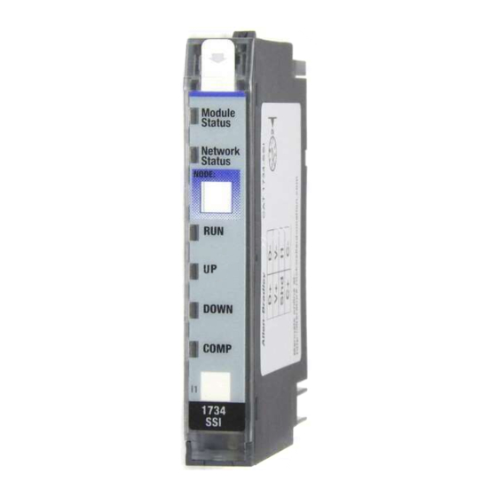
Chapter Diagnose Problems About This Chapter Read this chapter for information about how to troubleshoot using the module indicators. Use the Indicators for Use these indicators to help you troubleshoot problems with your 1734-SSI module. Troubleshooting Module status Module Status... - Page 36 Chapter 5 Diagnose Problems Indication Probable Cause Recommended Action Network Status Device is not online. Apply power to device. – Device has not completed dup_MAC_id test. – Device not powered - check module status indicator. Flashing Green Device is online but has no connections in the None –...
-
Page 37: About This Appendix
Appendix Configure Modules in RSLogix 5000 Software About This Appendix Read this appendix for information about how to configure your modules in RSLogix 5000 software, including how to complete entries on the following dialogs, which are not available for Listen Only connections. •... -
Page 38: Configure Your Module
I/O configuration to include selecting a controller and communication module. 2. Add a 1734-SSI specialty module, according to the instructions in your adapter user manual. 3. From the General dialog, access the following by clicking at the top of the dialog, completing the entries as explained in this chapter. -
Page 39: Work With The Feedback Dialog
Configure Modules in RSLogix 5000 Software Appendix A Work with the Feedback Follow these procedures to complete entries for the Feedback dialog. Dialog 1. From the General dialog, click Feedback to display the Feedback dialog. 2. From the Feedback dialog, complete entries, referring to the table. 3. -
Page 40: Work With The Conversion Dialog
Appendix A Configure Modules in RSLogix 5000 Software Work with the Conversion Follow these procedures to complete entries for the Conversion dialog. Dialog 1. From the General dialog, click Conversion to display the Conversion dialog. 2. From the Conversion dialog, complete entries, referring to the table. 3. -
Page 41: Work With The Input Registration Dialog
Configure Modules in RSLogix 5000 Software Appendix A Work with the Input Follow these procedures to complete the Input Registration dialog. Registration Dialog 1. From the General dialog, click Input Registration to display the dialog. 2. From the Input Registration dialog for Input Latch select one of these, with Off being the default. -
Page 42: Work With The Watch Position Dialog
Appendix A Configure Modules in RSLogix 5000 Software Work with the Watch Follow these procedures to complete the entries for the Watch Position dialog, referring to the Comparators 1 and 2 section of the Set and Operate Your Position Dialog Module chapter for a description of: •... -
Page 43: Rockwell Automation Publication 1734-Um007E-En-P - October
Configure Modules in RSLogix 5000 Software Appendix A • For Manual mode, click a value for Comparator Control 0 and 1 and complete entries for Comparator Value 0 and 1, noting that in the figure the value shows Up Direction for Comparator Control 0. Comparator Control 0 and 1 Comparator Value 0 and 1 Automatic... - Page 44 Appendix A Configure Modules in RSLogix 5000 Software Notes: Rockwell Automation Publication 1734-UM007E-EN-P - October 2015...
- Page 45 28 module installation 11 monitor major module faults 32 EDS file 19 power 32 example mounting base assembly 10 use of 1734-SSI module with a 24-bit SSI mounting base removal 13 sensor 32 Rockwell Automation Publication 1734-UM007E-EN-P - October 2015...
- Page 46 Index node commissioning tool 16 node setting (out of box) 16 parameter setting 17 positioning the keyswitch 11 produced bit and byte definitions 21 real-time information 22 removable terminal base installation 12 RSLogix 5000 software 37 RSNetWorx for DeviceNet software 15 setting module parameters 17 software RSNetworx for DeviceNet 15...
- Page 48 Rockwell Automation Support Rockwell Automation provides technical information on the Web to assist you in using its products. http://www.rockwellautomation.com/support you can find technical and application notes, sample code, and links to software service packs. You can also visit our Support Center at https://rockwellautomation.custhelp.com/ for software updates, support chats and forums, technical information, FAQs, and to sign up for product notification updates.
Need help?
Do you have a question about the 1734-SSI and is the answer not in the manual?
Questions and answers