TMQ AP4 Operation And Installation Manual
Hide thumbs
Also See for AP4:
- Operation and installation manual (63 pages) ,
- Installation and service manual (48 pages)
Table of Contents
Advertisement
Advertisement
Table of Contents

Related Manuals for TMQ AP4


Summary of Contents for TMQ AP4
- Page 1 TMQ – AP4 (AP4S10 Rev 4.96) OPERATION AND INSTALLATION MANUAL www.tmq.com.au...
-
Page 2: Table Of Contents
Selection Switch- Standard or Heavy Duty Feedback ......29 Heavy Duty Rudder Feedback Installation Diagram ......30 Standard Rudder Feedback Installation Diagram ....... 31 Installation of Remote Units ..............32 Remote Calibration................33 NMEA Connection ................. 33 TMQ AP4 Autopilot (AP4S10) 2 of 62 Version 4.96 9/10/2017... - Page 3 Heading Data Output Selection ............36 Heading Data Input ................36 External Alarm Installation ..............37 Wiring Connections – AP4 Rear Panel ..........38 Examples - Drive Connection Diagrams ..........40 General Information - Drive Units ............41 Commissioning Checks ................42 Post Installation Checks .................
-
Page 4: Introduction
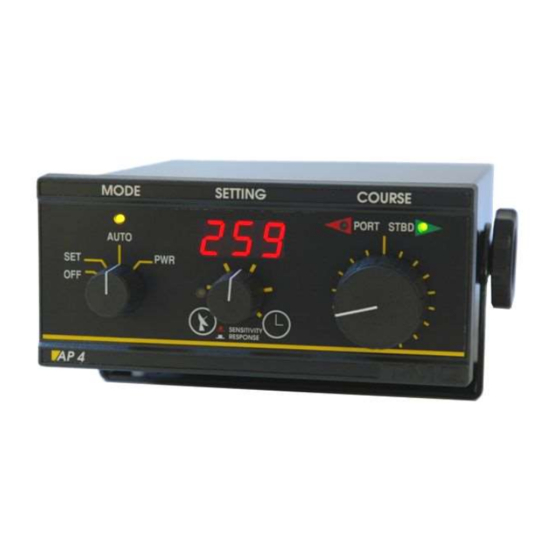
OR OTHER VESSELS. Overview The AP4 autopilot is a rugged & reliable pilot for use on all sorts of vessels, motor or sail, commercial or pleasure. The front panel has large control knobs for ease of use in all sea conditions. It has various special modes of operation to cater for all different requirements. -
Page 5: Autopilot Operation - Standard
(optional at extra cost) if the pipe size and brand of hydraulic system is specified. Autopilot Operation - Standard The following is a brief overview of the capabilities of the AP4 autopilot. Each is described in more detail later in following pages. TMQ AP4 Autopilot (AP4S10) 5 of 62 Version 4.96... -
Page 6: Set (Standby)
The digital display shows the vessels current magnetic course. Watch Alarm may be set (if required) Hand remote or steering lever (if installed) is ignored at first turn on. TMQ AP4 Autopilot (AP4S10) 6 of 62 Version 4.96 9/10/2017... -
Page 7: Auto
Each full rotation of course change knob gives 24º Possible alarms Off course (more than 45º) Watch timer (if set) FUS Indicated advises the internal fuse is open TMQ AP4 Autopilot (AP4S10) 7 of 62 Version 4.96 9/10/2017... -
Page 8: Power Steering
How to adjust the auto mode is explained in the section “Sensitivity & Rudder Adjustments” and also. If necessary some advanced settings, they are described in the sections “AP4 Special Modes” and “Adjusting the PID control”. Engaging GPS Mode ... -
Page 9: Watch Timer Mode
Press the GPS button GPS light is out Pilot locks on to current heading of If no GPS data or AP4 does not receive the data Autopilot maintains lock on the current course No GPS data alarm will sound ... -
Page 10: Commercial Boat Watch Timer
Note: Once the commercial watch alarm has been enabled, it cannot be disabled by the user. To enable the commercial watch timer alarm Switch AP4 to SET mode. Hold down the GPS button and press TIMER button ... -
Page 11: Autopilot Operation - Remote Control
Autopilot Operation - Remote Control The following is a brief overview of the capabilities of the AP4 autopilot with remote control units. Each is described in more detail later in the manual. The RFU control mode must be selected in order to use the remotes, apart from the front panel knob and the jog levers. -
Page 12: Hand Remote Power Steer
The autopilot will return to SET mode. Active Remote The AP4 can be controlled with an active remote unit. Auto, Power Steer, GPS steering can be selected. Response and Rudder settings of AP4 can be adjusted. Special internal remote mode r-2 must be set. -
Page 13: Active Remote Auto Steer
Active Remote Auto Steer Note: AP4 must be set to r-2 special remote mode To engage auto steer mode with Active Remote Unit Switch AP4 MODE to SET, AUTO or PWR Set remote knob to centre position ... -
Page 14: Steering Lever & Electric Helm Steering
Note: AP4 must be set for the correct special remote mode (see page 32) The boat may be steered using a steering lever with the AP4. Special internal remote modes r-3, r-4, r-5 or r-6 must be set in AP4 depending on remote control connection. -
Page 15: Jog Switch Steering
A jog lever is a device comprising a lever under spring tension for centre reference and two switches for bi directional control. With AP4 set for JOG input, a number of operations have been included in the software to extend the use of the AP4 control for some navigational situations (refer to selection of special remote mode 908, r-7 or r-8 in the subsection “Special Modes Display Selection”... -
Page 16: Sensitivity & Rudder Adjustments
To exit JOG control switch the AP4 to OFF/AUTO/PWR Jog Switch Steering with AP4 in AUTO Switch AP4 to AUTO – at initial switch on the system will operate in normal autopilot control; the jog lever will have no effect at this stage ... - Page 17 Note: The sensitivity and rudder are normally adjusted together with sensitivity being adjusted first, then rudder ratio. The sensitivity should be adjusted so that the AP4 is not continually driving back and forth (hunting) as this can prematurely wear your steering system If the centre knob is left out after the sensitivity is set, when 3 seconds has elapsed, the AP4 display will read rudder angle.
-
Page 18: Alarms
The external alarm output is turned on 1 minute after the internal alarm begins to sound. Angle Off Course Alarm The alarm pattern is 0.2 seconds on, 0.2 seconds off when vessel is more than 45 degrees from course-to-steer. TMQ AP4 Autopilot (AP4S10) 18 of 62 Version 4.96 9/10/2017... - Page 19 It is intended for being connected to an external BNWAS controller. In any other mode, different from auto, the external alarm will be open circuit. From the factory, this alarm mode is OFF. TMQ AP4 Autopilot (AP4S10) 19 of 62 Version 4.96...
-
Page 20: Installation Of Autopilot
Installation of Autopilot EMC Considerations & Precautions: All TMQ equipment and accessories are designed to the best industry standard for use in the marine environment. Their design and manufacture conforms to the appropriate Electromagnetic Compatibility (EMC) standards, but good installation is required to ensure that performance is not compromised. -
Page 21: List Of Components
* The Rudder Feedback Unit with 14 m cable may be not attached TMQ Autopilots are intended for use in three (3) basic configurations: 1. AP4 can be used to control most brands of drive units or solenoid control valves (hydraulic). System components: ... -
Page 22: Installation Of Main Control Unit
Rotate compass in the bracket if necessary until the arrow faces the bow of the boat Route the cable to the AP4 control position Connect the compass cable to NMEA 6 pin Connector on rear of unit. TMQ AP4 Autopilot (AP4S10) 22 of 62 Version 4.96... - Page 23 Ground) information to improve compass operation on a steel vessel. The green wire is positive, and the blue is negative. ELECOM Wiring Colour Code Blue TXD+ Yellow (data from Compass) RXD+ Green (data to compass) RXD− Shield (Black) TMQ AP4 Autopilot (AP4S10) 23 of 62 Version 4.96 9/10/2017...
-
Page 24: Installing A Compass-Top Sensor
The magnetic sensor unit or compass-top-sensor, which is supplied with your AP4 autopilot, is fitted with a plug, which fits into the COMPASS socket on the rear of the autopilot. If the cable must be extended, we recommend that TMQ 5- core shielded extension cable be used. -
Page 25: Installing A Magnetic Sensor Unit (Fluxgate Compass)
Plug compass cable into AP4 autopilot Check AP4 display reads the same as the boat compass when pilot is switched on. Note: The compass can be mounted outside the hull of the boat if required (eg: on a mast of a yacht). However, places to be avoided are low in the hull near an engine or machinery because of magnetic interference or too high up a mast because of excessive movement. -
Page 26: Magnetic Sensor Unit & Compass Top Sensor Interchange
If the magnetic sensor unit and compass top sensor are interchanged, the compass detector DIP switches must be altered. The top cover of the AP4 has to be removed. The DIP switch is identified as component DIP2 on the PCB component overlay diagram at the rear of this manual. -
Page 27: Installation Of Rudder Feedback
In case of not fitting a RFU, the device must be set to work in non RFU mode via special mode 922. See more details on page 52, “Operating Without RFU” section. TMQ AP4 Autopilot (AP4S10) 27 of 62 Version 4.96... -
Page 28: Mounting
Connect 3 core cable to the RFU terminal strip (RFUH only) Route the rudder feedback cable to the AP4 position Connect the RFU cable to the RUDDER socket of the AP4 Installation Checks Turn the helm slowly from hard over to hard over and observe the movement of the rudder feedback arm ... -
Page 29: Selection Switch- Standard Or Heavy Duty Feedback
The AP4 is normally dispatched from the factory as ordered. However, when installation of the feedback is completed on the boat the RFUS / RFUH selection switch in the AP4 control unit should be checked for correct selection. Selecting between RFUS and RFUH: ... -
Page 30: Heavy Duty Rudder Feedback Installation Diagram
Note: DIP 1 Switch 2 is used for heading input from a GPS using the COG information. Normally set to Compass (OFF). Refer “NMEA Connection”, page 33. Heavy Duty Rudder Feedback Installation Diagram TMQ AP4 Autopilot (AP4S10) 30 of 62 Version 4.96 9/10/2017... -
Page 31: Standard Rudder Feedback Installation Diagram
Standard Rudder Feedback Installation Diagram TMQ AP4 Autopilot (AP4S10) 31 of 62 Version 4.96 9/10/2017... -
Page 32: Installation Of Remote Units
Route the cable to the AP4 control position Plug the cable into the REMOTE socket at the rear of the AP4 Remotes Calibration The remotes can be calibrated if required; this allows the full range of the steering input to be used. Each remote fitted has to be calibrated. -
Page 33: Remote Calibration
Check BEFORE realigning.. NMEA Connection The NMEA 6 pin socket at the rear of the AP4 (internally labelled T5 DATA) allows for the following connections: 1. GPS data input – for waypoint or GPS steering 2. -
Page 34: Nmea Socket - Pin Configuration
Pin 5 – TMQ data positive input Pin 6 – Power positive 10 VDC GPS Data Input The AP4 pilot will accept two forms of GPS data in NMEA 0183 format as follows: GPS Plotter data – APA, APB or XTE+BOD for waypoint steering –... -
Page 35: Heading Data Connections
Displays shows bearing to waypoint – BTW TMQ Second Station Display Connection When a TMQ second station display (AP56 *) is used with the AP4, it has a pre-wired plug to connect to the NMEA socket. Provision is made for GPS or C-Plot data input via two wires attached to the plug as follows: ... -
Page 36: Heading Data Output Selection
Press TIMER button to save the setting and exit the procedure Heading Data Input The AP4 pilot can accept NMEA 0183 heading data input from any source, for example, GPS compass or other electronic compass. which will connect to the internal terminal strip T4. -
Page 37: External Alarm Installation
A 12 Volt piezo buzzer with current draw not exceeding 250 milliamps should be used (TMQ Part No. SIREN). If a siren or alarm unit is used which draws in excess of 250 milliamps, this should be connected via a relay. -
Page 38: Wiring Connections - Ap4 Rear Panel
Connect SIREN + lead (red) to 10V Power on T4 Connect SIREN – lead (black) Alarm Negative Output T4 Route siren wires through cut out at rear of AP4 Replace top cover of AP4 To enable the commercial watch alarm, refer pages 10 and 18. - Page 39 Rudder Feedback Not used Negative ....Blue Not used RFU Signal ....Green + 5 Volts to RFU ..Red / Brown Compass White Blue (Square Wave Drive Signal) Yellow Green TMQ AP4 Autopilot (AP4S10) 39 of 62 Version 4.96 9/10/2017...
-
Page 40: Examples - Drive Connection Diagrams
Examples - Drive Connection Diagrams TMQ AP4 Autopilot (AP4S10) 40 of 62 Version 4.96 9/10/2017... -
Page 41: General Information - Drive Units
General Information - Drive Units The AP4 autopilot is capable of controlling reversing hydraulic pumps, mechanical drives, linear hydraulic drive systems, linear mechanical systems, solenoid valves on constant running pumps and relays When installing any drive system, refer to the manufacturers’ specifications and instructions. -
Page 42: Commissioning Checks
Solenoid Valves Links are provided to allow jog lever operation in conjunction with AP4 S9 Autopilot. These links should be cut when connecting the AP4 for solenoid operation where a jog lever is also fitted or an isolating switch must be installed. -
Page 43: Pre Sailing Dockside Tests
Note: APART FROM INSTALLATION MODE, AT NO OTHER STAGE SHOULD THE AUTOPILOT DRIVE THE RUDDER INTO THE MECHANICAL STOPS. IF THIS IS ALLOWED TO HAPPEN, DAMAGE TO THE AUTOPILOT MAY RESULT TMQ AP4 Autopilot (AP4S10) 43 of 62 Version 4.96 9/10/2017... -
Page 44: Sea Trials
Check Rudder Drive Speed The speed a rudder is moved by the autopilot drive unit will affect the steering responsiveness of the AP4. A rudder lock to lock time of approximately 15 seconds* is required for good course holding. *Optimum rudder speed will vary between vessels. A larger ship or slower boat may require a slower speed. -
Page 45: Rudder Limits Setting
The starboard limit S_L functions in the same way for rudder angles to starboard. The display symbols do not appear when AP4 is in the SET mode. To Set Rudder Limits Manually ... - Page 46 Check display reads between 150 and 250 (eg: 220) Press TIMER button - this sets the STARBOARD LIMIT To Set Rudder Limits Automatically (Installation Mode) Switch AP4 to SET mode Drive the rudder to its central position Hold down GPS button ...
- Page 47 E1, meaning that the reversing pump is not moving the rudder, or the rudder feed back did not move. To check Rudder Limits Rotate MODE switch on AP4 to PWR Rotate COURSE knob anticlockwise (to port) until pilot stops driving rudder ...
-
Page 48: Compass Calibration
The calibration should only be done if the compass is known to be inaccurate. If the AP4 compass displays a constant offset (eg the autopilot compass reads 3 degrees high on all bearings), simply rotate the AP4 compass case to align bearings with the ships compass. -
Page 49: Calibrating Tmq Electronic Compass - Elecom
North (000 on ships compass) and, if necessary, rotate outer case of AP4 compass in its bracket until heading display reads 000. It is important to realise that on any vessel the ships compass can have heading errors as a result of the vessels magnetic signature. -
Page 50: Ap4 Special Modes
AP4 Special Modes AP4 Special modes are internal settings which allow different operations to be performed by the AP4. Also, special modes allow certain parameters to be set which control the AP4 operation. To Enter Special Modes ... - Page 51 Heading deadband (default: 10 1 ) – This deadband is associated to the readings from the compass. Set with (1) or without (0) RFU control mode (default: 1) TMQ AP4 Autopilot (AP4S10) 51 of 62 Version 4.96 9/10/2017...
-
Page 52: Operating Without Rfu
The more responsive the vessel is to the rudder movement, the setting should be lower. Usually, for larger boats with high rudder inertia, it will require a longer pulse. TMQ AP4 Autopilot (AP4S10) 52 of 62 Version 4.96 9/10/2017... -
Page 53: Adjusting The Pid Control
It is intended to keep the direction inside the dead band. The adjustment of the gain for this parameter was explained in the section “AP4 Special Modes” (display selection 918); Derivative value: After setting the proportional value for getting the desired responsiveness, it may be experienced some overshoot (“hunting”). -
Page 54: Following A Track (Waypoint)
The adjustment of the gain for this parameter was explained in the section “AP4 Special Modes” (display selection 915); Integral value:... - Page 55 Therefore, the integral gain (925) was increased until a good result was achieved in the middle of the tide currents. Back to the calm waters, it kept on track as well. TMQ AP4 Autopilot (AP4S10) 55 of 62 Version 4.96...
-
Page 56: Optional Extras
Optional Extras There are a range of optional extras that can be connected to the TMQ AP4 system as the need or circumstances require. Further information can be obtained from the TMQ website at www.tmq.com.au Rudder Angle Indicator The rudder angle indicator is a... - Page 57 Linear drives Single rod linear drives can be fitted to a wide variety of vessels. May be attached directly to the tiller or rudder quadrant. TMQ AP4 Autopilot (AP4S10) 57 of 62 Version 4.96 9/10/2017...
-
Page 58: Declaration Of Conformity
Fax: +61 7 3640 5699 Declares under our sole responsibility that the products: AP4 Autopilot, Compass Sensor, Rudder Feedback unit and remote accessories, all units interconnected with necessary cables and external connections as a system to which this declaration relates, is in conformity with Standard(s):... -
Page 59: Warranty
TMQ Electronics shall not be liable for damage or loss incurred resulting from the use and operation of this product. TMQ Electronics reserves the right to make changes or improvements to later models without incurring the obligation to install similar changes to equipment already supplied. -
Page 60: Troubleshooting
No compass input Defective drive cable connections Failure of drive switching circuit in AP4 (FET’s) Defective MODE switch in AP4 FUS Displayed open Fuse Internal 15A Blade Fuse AP4 working but rudder does not move Possible fault ... - Page 61 AP4 drives rudder hard over when switched to AUTO Possible fault Rudder feedback cable disconnected from AP4 Defective rudder feedback cable Disconnected rudder feedback linkage Broken rudder feedback linkage or arm Rudder feedback unit failure...
- Page 62 TMQ ELECTRONICS Unit 18/17 Rivergate Place Murarrie Qld 4172 Phone 07 3640 5600 Email: tmq@tmq.com.au TMQ INTERNATIONAL PTY LTD TMQ AP4 Autopilot (AP4S10) 62 of 62 Version 4.96 9/10/2017...
Need help?
Do you have a question about the AP4 and is the answer not in the manual?
Questions and answers