Table of Contents
Advertisement
Quick Links
Advertisement
Table of Contents

Related Manuals for TMQ AP9


Summary of Contents for TMQ AP9
- Page 1 TMQ AP9 (AP9 V6 Rev 3) OPERATION AND INSTALLATION MANUAL www.tmq.com.au...
-
Page 2: Table Of Contents
................24 UDDER EEDBACK NSTALLATION Precautions..................... 24 Selection Switch- Standard or Heavy Duty Feedback........25 Wiring to to AP9 for RFU andCompass............26 Heavy Duty Rudder Feedback Installation Diagram......... 27 Standard Rudder Feedback Installation Diagram..........28 ................. 29 NSTALLATION OF EMOTE NITS Remote Calibration.................. - Page 3 ..................41 UDDER IMIT DJUSTMENT Internal Rudder Limits ................... 41 Setting/Resetting Rudder Limit ............... 41 ....................42 OMPASS ALIBRATION ......................43 PECIAL ODES OPTIONAL EXTRAS .................... 47 WARRANTY......................50 TMQ AP9 Autopilot (V6.0 - 965) Page 3 of 51 31/1/2017...
-
Page 4: Introduction
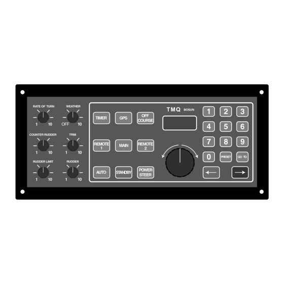
COURSE SUFFICIENTLY TO ENDANGER YOUR OWN OR OTHER VESSELS. Overview The TMQ AP9 autopilot is a hybrid of digital and analogue technology to give the best features - excellent steering characteristics with digital compass display, keypad course input, GPS and gyro interfaces and manual controls for adjusting parameters to suit any boat. -
Page 5: Autopilot Operation - Standard
Note: Power to the autopilot is supplied via the Weather control. Turn the knob control in a clockwise direction to apply power to the AP9; this will initially put the pilot into Standby mode. -
Page 6: Standby
Hand remote or steering lever (if installed) is ignored at first turn on (except when special mode set *) · Other special remote modes are accessible (refer later in manual) TMQ AP9 Autopilot (V6.0 - 965) Page 6 of 51 31/1/2017... -
Page 7: Auto
Pilot will change course to port by 1º for each button press · Press green arrow button · Pilot will change course to starboard by 1º for each button press · Display will change to indicate the new course TMQ AP9 Autopilot (V6.0 - 965) Page 7 of 51 31/1/2017... -
Page 8: Power Steering Mode
Notes: There are many variations on power-steering with a remote unit (eg: Electric Wheel or Steering Levers). Refer to your dealer or TMQ Electronics. Some information is available in the diagrams detailing remote unit operation and connections on pages 20 and 43 If your vessel requires counter-rudder* while steering in auto mode, you may wish to set the counter rudder control to "1"... - Page 9 Press STANDBY button to return pilot to standby mode · Press POWER button to return pilot to power steer mode Possible alarm If there is no GPS data or the AP9 does not receive the data · Autopilot maintains the current course ·...
-
Page 10: Watch Timer Mode
Timer light will be off Commercial Boat Watch Timer Used where survey regulations for commercial vessels require a watch timer (which includes an external alarm) fitted with an autopilot. TMQ AP9 Autopilot (V6.0 - 965) Page 10 of 51 31/1/2017... -
Page 11: Controls
When the commercial timer is enabled and the autopilot is in control of the boat (i.e: in AUTO, GPS or REMOTE AUTO mode), the AP9 internal alarm sounds after completion of the selected interval and the louder external alarm one minute later, unless the timer is previously reset. -
Page 12: Weather (Heading Sensitivity)
Weather (Heading Sensitivity) The main power switch is incorporated in this variable control. When in the OFF position no power is applied to the AP9. By turning the knob clockwise from the OFF position, the switch applies power to the AP9. -
Page 13: Trim
An external control on the front panel of the AP9 can be used to limit the amount of rudder travel to a narrower angle or range. (In some special circumstances this control can be used to limit the rate of turn of the vessel). -
Page 14: Rudder Control (Rudder Ratio)
Each is described in more detail later in the manual. Hand remote The AP9 can be controlled with a hand remote unit. Auto and power steer modes can be selected. Special remote response mode r-1 must be set in AP9. -
Page 15: Hand Remote Auto Steer
· Boat is now steered manually To disengage remote auto steer mode with Main Control · Select STANDBY, AUTO or POWER STEER on the AP9 · Boat is now steered from the Main Control panel Hand Remote Power Steer To engage power steer mode with Hand Remote ·... -
Page 16: Steering Lever & Electric Helm Steering
If not, auto mode or GPS mode will not steer accurately. Steering Lever & Electric Helm Steering (AP9 must be set for the correct special remote mode - see page 58) Steering Levers and Electric Helms provide full follow up steering. A steering lever or electric helm operates in a similar way to a hand remote control. -
Page 17: Autopilot Installation
Autopilot Installation EMC Considerations & Precautions:- All TMQ equipment and accessories are designed to the best industry standard for use in the marine environment. Their design and manufacture conforms to the appropriate Electromagnetic Compatibility (EMC) standards, but good installation is required to ensure that performance is not compromised. -
Page 18: List Of Components
Interconnection:- If your autopilot is to be connected to other navigational equipment using a cable not supplied by TMQ, a suppression ferrite MUST always be fitted to the cable close to the TMQ unit. List of Components The AP9 autopilot control system when packed has the following components: ·... -
Page 19: Installation Of Main Control Unit
Select a drive unit interconnection cable of appropriate current rating to prevent voltage drop Compass Installation There are three types of compass suitable for this autopilot - a TMQ compass-top sensor (CTSB), a TMQ fluxgate compass (COMMAGB) or TMQ electronic compass (ELECOM) Installing a Compass-Top Sensor A compass top sensor should be used as the pilot heading reference unit for steel boats. -
Page 20: Installing A Magnetic Sensor Unit (Fluxgate Compass)
· Connect the cable into AP9 compass terminal strip · Before fixing the CTSB to the compass surface, switch on the AP9, align the CTSB carefully so that the AP9 display reads the same as the boat magnetic compass ·... -
Page 21: Tmq Fluxgate Compass Mounting Options
· Ensure there are no radios or radio aerials or cables nearby · Check other side of bulkheads or behind dashes for any likely interference · Install compass horizontally TMQ AP9 Autopilot (V6.0 - 965) Page 21 of 51 31/1/2017... - Page 22 Rotate compass in the bracket if necessary until the arrow faces the bow of the boat · Route the cable to the AP9 control position · Connect the compass cable wires to the internal connection strip of the AP9 marked T5 Remotes and T6 NMEA as follows: · T5 Pin 1 10V ·...
-
Page 23: E-Compass Mounting
E-Compass Mounting Vessel Bow Connections (Note: Page 31 for AP9) – Wire Colour Code Wire Signal 10 Volts Black Shield Negative Yellow IN + Blue IN - and Negative Green Data 1 Connections in AP9 TMQ AP9 Autopilot (V6.0 - 965) -
Page 24: Rudder Feedback Installation
Select a position adjacent to the tiller arm · Install the mounting bracket to accommodate the rudder feedback unit with its arm parallel to and pointing in the same direction as the tiller TMQ AP9 Autopilot (V6.0 - 965) Page 24 of 51 31/1/2017... -
Page 25: Selection Switch- Standard Or Heavy Duty Feedback
Selection Switch- Standard or Heavy Duty Feedback The AP9 is normally dispatched from the factory as ordered. However, when installation of the feedback is completed on the boat the RFUS / RFUH selection switch in the AP9 control unit should be checked for correct selection. -
Page 26: Wiring To To Ap9 For Rfu Andcompass
(DO NOT CONNECT TO RUD2) Compass Wiring Wire compass to correct colour. Green Signal Return Signal return Yellow Signal Return White Signal Return Blue Square Wave drive to compass 1500Hz TMQ AP9 Autopilot (V6.0 - 965) Page 26 of 51 31/1/2017... -
Page 27: Heavy Duty Rudder Feedback Installation Diagram
Heavy Duty Rudder Feedback Installation Diagram TMQ AP9 Autopilot (V6.0 - 965) Page 27 of 51 31/1/2017... -
Page 28: Standard Rudder Feedback Installation Diagram
Standard Rudder Feedback Installation Diagram TMQ AP9 Autopilot (V6.0 - 965) Page 28 of 51 31/1/2017... -
Page 29: Installation Of Remote Units
· Connect the cable internally to terminal strip T4 Remotes socket (or terminal strip T2 Wheel depending on the special mode of operation set in the AP9) Wheel Input Terminals – T2 The input is active in “STANDBY” mode . Pressing POWER will engage the encoder. -
Page 30: Remote Calibration
Press MAIN button to exit calibration and save the setting Note: If the boat does not steer straight ahead when the remote control course knob is centred, the rudder feedback may need realignment. TMQ AP9 Autopilot (V6.0 - 965) Page 30 of 51 31/1/2017... -
Page 31: Nmea Connection
Pin 8 – GPS data + input GPS Data Input The AP9 pilot will accept two forms of GPS data in NMEA 0183 format as follows: · GPS Plotter data – APA, APB or XTE + BOD for waypoint steering – pilot display shows the bearing the pilot will steer to the waypoint (BTW on the plotter). -
Page 32: Gps Data Input Connection
Displays shows bearing to waypoint - BTW TMQ Second Station Display Connection When a TMQ second station display (AP56*) is used with the AP9, they are connected to T5 Remotes and T6 NMEA terminal blocks. Wiring colour code connections are as follows: ·... -
Page 33: Heading Data Input
(COMMAGB - if fitted). If the NMEA data fails during operation, the unit will revert to the standard compass and the alarm will sound. The alarm can only be cancelled by turning the AP9 off and on again. -
Page 34: External Alarm Installation
A 12 volt piezo buzzer with current draw not exceeding 250 milliamps should be used (TMQ Part No. SIREN). If a siren or alarm unit is used which draws in excess of 250 milliamps, this should be connected via a relay. -
Page 35: Examples - Drive Connection Diagrams
Examples - Drive Connection Diagrams TMQ AP9 Autopilot (V6.0 - 965) Page 35 of 51 31/1/2017... -
Page 36: General Information - Drive Units
When mounted, fill with oil and purge air from system Solenoid Valves Links are provided to allow jog lever operation in conjunction with the AP9 Autopilot. The links should be cut when connecting the AP9 for solenoid operation. When cut (open circuit) the autopilot control only pulls the drive outputs low. Positive voltage is supplied to the solenoid common connection. - Page 37 Ensure all connections are tight. Recheck periodically. ALL CONSTANT RUNNING PUMPS SHOULD BE CONNECTED TO THE SUPPLY VIA AN ISOLATING SWITCH AND SUITABLE PROTECTION CIRCUIT – FUSE OR CIRCUIT BREAKER TMQ AP9 Autopilot (V6.0 - 965) Page 37 of 51 31/1/2017...
-
Page 38: Post Installation Checks
Pre Sailing Dockside Tests Turn helm to mid ships position. Turn on main power supply. AP9 in STANDBY Check rudder limits – adjust only if necessary. See Rudder Limits page 52. Determine vessel heading by a sighting on known heading or compass. -
Page 39: Sea Trials
Check compass headings against boat compass · Carry out compass calibration if necessary – see page 55 Note: It is rare for the AP9 heading and boat compass to agree exactly on every heading due to magnetic variations on the boat. Basic Trials... - Page 40 GPS inputs, waypoint steering, etc. Check the operational sections of this manual for relevant functionality testing. Always use open waterways for testing until you are familiar with the operation. TMQ AP9 Autopilot (V6.0 - 965) Page 40 of 51 31/1/2017...
-
Page 41: Rudder Limit Adjustment
The starboard limit S_L functions in the same way for rudder angles to starboard. Setting/Resetting Rudder Limit NOTE: Before resetting the rudder limits the Rudder Limit control on the front panel MUST be set fully clockwise. TMQ AP9 Autopilot (V6.0 - 965) Page 41 of 51 31/1/2017... -
Page 42: Compass Calibration
If the AP9 compass displays a constant offset (eg: the autopilot compass reads 3 degrees high on all bearings), simply rotate the AP9 compass case to align bearings with the ships compass, it is not necessary to re-calibrate the compass as described below. -
Page 43: Special Modes
· Press and hold pressed STANDBY button · Press GOTO button · A double beep will be heard as the AP9 accepts the calibration and exits calibration mode · Display will now read boat heading · Check the alignment of the compass by steering due North (000º) ·... - Page 44 Note: If COG is used to generate heading (as heading reference), then ECVTG will be the serial data out. This is not dependent on the serial data output selection. TMQ AP9 Autopilot (V6.0 - 965) Page 44 of 51 31/1/2017...
- Page 45 Remote Mode Option Details (908) Remote Mode 1 ( 2 Standard TMQ Remotes) · Remote Unit 1 on Input “Wiper 1” with Control Line “Select 1” being held Negative for Auto, Positive for Power Steer. · Remote Unit 2 on Input “Wiper 2” with Control Line “Select 2” being held Positive for Power Steer.
- Page 46 The input is active in “STANDBY” mode . Pressing POWER will engage the encoder. The input is active in “POWER” mode. The POWER control knob (front panel) button is not active TMQ AP9 Autopilot (V6.0 - 965) Page 46 of 51 31/1/2017...
-
Page 47: Optional Extras
Optional Extras There are a range of optional extras that can be connected to the AP9 system as the need or circumstances require. Further information can be obtained from the TMQ website at www.tmq.com.au Rudder Angle Indicator The rudder angle indicator is a... - Page 48 Electric Wheel The TMQ Electric steering wheel provides precise, light steering on any vessel with a power steering system installed. It simplifies vessel fit out by eliminating long hydraulic lines to the helm position Reversible pumps Hydraulic pumps are available...
- Page 49 Fax: +61 7 3640 5699 Declares under our sole responsibility that the products: AP9 Autopilot, Compass Sensor, Rudder Feedback unit and remote accessories, all units interconnected with necessary cables and external connections as a system to which this declaration relates, is in conformity...
-
Page 50: Warranty
The owner is also responsible for providing reasonable maintenance and weather protection of the equipment. TMQ Electronics shall not be liable for damage or loss incurred resulting from the use and operation of this product. TMQ Electronics reserves the right to make changes or improvements to later models without incurring the obligation to install similar changes to equipment already supplied. - Page 51 TMQ ELECTRONICS Unit 18/17 Rivergate Place Murarrie Qld 4172 Phone 07 3640 5600 Email: tmq@tmq.com.au TMQ INTERNATIONAL PTY LTD TMQ AP9 Autopilot (V6.0 - 965) Page 51 of 51 31/1/2017...
Need help?
Do you have a question about the AP9 and is the answer not in the manual?
Questions and answers